- Cisco Community
- シスコ コミュニティ
- ネットワークインフラストラクチャ
- [TKB] ネットワークインフラ ドキュメント
- Cisco4500シリーズスイッチのVSS環境設定
- RSS フィードを購読する
- 新着としてマーク
- 既読としてマーク
- ブックマーク
- 購読
- 印刷用ページ
- 不適切なコンテンツを報告
- RSS フィードを購読する
- 新着としてマーク
- 既読としてマーク
- ブックマーク
- 購読
- 印刷用ページ
- 不適切なコンテンツを報告
2013-10-29 04:39 PM
序文:
CiscoのVirtual Switching System(VSS)はCisco Ctalyst 4500-EシリーズのスイッチとCisco Catalyst Supervisor Engine 7-E、もしくは7-LE、mのしくはふたつのCatalyst 4500-Xシリーズのスイッチを一つの仮想スイッチにプールするクラスタリング技術です。
VSSでは、データ面のどちらのクラスタスイッチも同時にシャーシ内で稼働しています。
VSSメンバーはVSSメンバー間で標準GB、もしくは10GBのイーサネット接続を使っているVirtual Switch Links(VSLs)によって接続されいます。
VSLsはVSSメンバー間のコントロール面の伝達に加えて正常なユーザ情報を運ぶことができます。
VSS設定環境の物理的と論理的な技術:
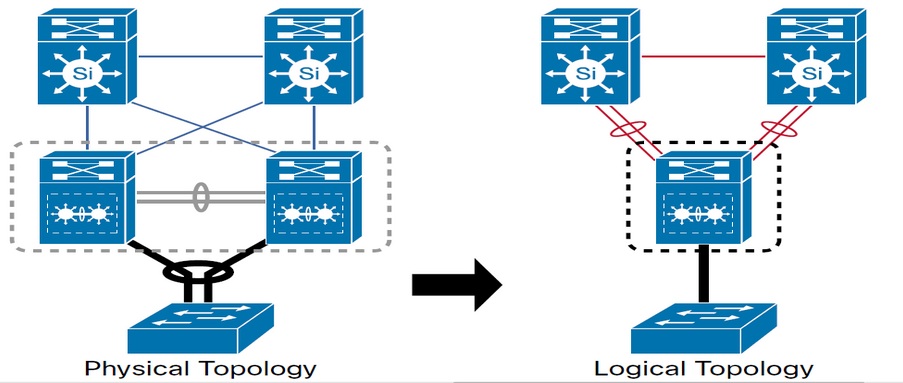
このドキュメントはCatalyst 4500シリーズのスイッチのVSSの設定をどのように構築するかを記述したものです。
Cisco4500VSSで覚えておくキーポイント:
1)
Configuration/CapabilityはCatalyst 4500-E上で管理者をサポートしています: VSSはSupervisor Engine 7-Eもしくは7-LEをサポートしています(同一の組み合わせで)。
ハードウェアでのサポートの詳細情報4500 VSS Hardware Requirementを参照してください。
2)
ソフトフェアの要求: Cisco IOS XE 3.4.0SGとROMMON IOSバージョン15.0(1r) SG7は後に開放されるVSSサポートです。(How to Upgrade Cisco 4500 SUP7-E & Sup7L-E ROMMON To support VSSを参照してください。)
3)
ミニマムライセンス: VSSはIP BASEもしくはENTERSERVICES LICENSEと一緒に動作する; LAN BASEとは一緒に動作しません。
Software Acticvation Licenseingの情報はCisco Catalyst 4500E Supervisor 7-E and 7L-E and Cisco Catalyst 4500-X Series Software Activation Licensing Deployment Guideを参照ください。
4)
Single-sup cross-chassis VSSサポート: yes.
5)
Quad-sup VSSコンフィグレーションとIn-chassisの冗長sups: 動作中のアップリンク状態のROMMONモードのIn-chassisの冗長sups
6)
10ギガビットのイーサネットVirtual Switch Link(VSL)と1ギガビットのイーサネットVSLもサポートしています。
7)
SSOとNonStop Forwarding(NSF)はスイッチで構成されなければなりません。もしVSSがSSO冗長性のための要求に合わない場合、対等なスイッチとの関係の確立をすることができなくなります。
Catalyst 4500/4500-Xシリーズのスイッチ: VSSはRoute Processor Redundancy(RPR)モードをサポートしません。
必要条件:
Cisco 4500でVSSを設定する前にハードウェアとソフトウェアの必要条件を確認してください。
SW1#sh ver | in IOS
Cisco IOS Software, IOS-XE Software, Catalyst 4500 L3 Switch Software (cat4500e-UNIVERSAL-M), Version 03.04.00.SG RELEASE SOFTWARE (fc3)
Cisco IOS-XE software, Copyright (c) 2005-2010, 2012 by cisco Systems, Inc.
All rights reserved. Certain components of Cisco IOS-XE software are
documentation or "License Notice" file accompanying the IOS-XE software,
or the applicable URL provided on the flyer accompanying the IOS-XE
SW1#sh ver | in ROM
ROM: 15.0(1r)SG7
System returned to ROM by power-on
SW1#sh license image levels
Module name Image level Priority Configured Valid license
--------------------------------------------------------------------
WS-X45-SUP7-E entservices 1 YES entservices
ipbase 2 NO ipbase
lanbase 3 NO lanbase
Module Name Role Current Level Reboot Level
--------------------------------------------------------------------
WS-X45-SUP7-E Active entservices entservices
SW2#sh ver | in IOS
Cisco IOS Software, IOS-XE Software, Catalyst 4500 L3 Switch Software (cat4500e-UNIVERSAL-M), Version 03.04.00.SG RELEASE SOFTWARE (fc3)
Cisco IOS-XE software, Copyright (c) 2005-2010, 2012 by cisco Systems, Inc.
All rights reserved. Certain components of Cisco IOS-XE software are
documentation or "License Notice" file accompanying the IOS-XE software,
or the applicable URL provided on the flyer accompanying the IOS-XE
SW2#sh ver | in ROM
ROM: 15.0(1r)SG7
System returned to ROM by power-on
SW2#sh license image levels
Module name Image level Priority Configured Valid license
--------------------------------------------------------------------
WS-X45-SUP7-E entservices 1 YES entservices
ipbase 2 NO ipbase
lanbase 3 NO lanbase
Module Name Role Current Level Reboot Level
--------------------------------------------------------------------
WS-X45-SUP7-E Active entservices entservices
設定:
Step1: 仮想スイッチドメインの割り当てとスイッチの番号
初めに、VSSの両スイッチにある同じ仮想スイッチドメイン番号を設定する必要があります。
仮想スイッチドメインは1~255の数字で割り当てられます。
ドメイン番号の後に一つのスイッチのスイッチ番号を1に、もう片方のスイッチの番号を2に設定しなければなりません。
SW1#conf t
Enter configuration commands, one per line. End with CNTL/Z.
SW1(config)#switch virtual domain 10
Domain ID 10 config will take effect only
after the exec command 'switch convert mode virtual' is issued
SW1(config-vs-domain)#switch 1
SW1(config-vs-domain)#exit
SW1(config)#
SW2#conf t
Enter configuration commands, one per line. End with CNTL/Z.
SW2(config)#switch virtual domain 10
Domain ID 10 config will take effect only
after the exec command 'switch convert mode virtual' is issued
SW2(config-vs-domain)#switch 2
SW2(config-vs-domain)#exit
SW2(config)#
Step2: VSLポートチャネルの設定
その後、各スイッチに一意のポートチャネルをVSLに設定する必要があります。
通信している間、VSSはVSS Activeスイッチに両ポートチャネルの設定を行います。
もしVSS StandbyスイッチのVSLポートチャネル番号が他の用途で設定されている場合、VSSはRPRモードになります。
これを避けるには、両ポートチャネル番号がどちらのスイッチでも使用可能なことを確認します。
SW1(config)#int port-channel 5
SW1(config-if)#switchport
SW1(config-if)#switch virtual link 1
SW1(config-if)#no shut
SW1(config-if)#exit
*Jan 24 05:19:57.092: %SPANTREE-6-PORTDEL_ALL_VLANS: Port-channel5 deleted from all Vlans
SW2(config)#int port-channel 10
SW2(config-if)#switchport
SW2(config-if)#switch virtual link 2
SW2(config-if)#no shut
SW2(config-if)#exit
SW2(config)#
*Jan 24 05:14:17.273: %SPANTREE-6-PORTDEL_ALL_VLANS: Port-channel10 deleted from all Vlans
Step3: VSLポートの設定
VSL Physicalポートをポートチャネルに追加する必要があります。
この例図では、スイッチ1のインターフェイスギガビットイーサネット7/3と7/4はスイッチ2の4/45と4/46に接続されています。
SW1(config)#int range gig7/3 - 4
SW1(config-if-range)#switchport mode trunk
SW1(config-if-range)#channel-group 5 mode on
WARNING: Interface GigabitEthernet7/3 placed in restricted config mode. All extraneous configs removed!
WARNING: Interface GigabitEthernet7/4 placed in restricted config mode. All extraneous configs removed!
SW1(config-if-range)#exit
SW2(config)#int range gig4/45 - 46
SW2(config-if-range)#switchport mode trunk
SW2(config-if-range)#channel-group 10 mode on
WARNING: Interface GigabitEthernet4/45 placed in restricted config mode. All extraneous configs removed!
WARNING: Interface GigabitEthernet4/46 placed in restricted config mode. All extraneous configs removed!
SW2(config-if-range)#exit
メモ:
一度インターフェイスが"channel-group"コマンドでVSLポートチャネルに入れられたら、インターフェイスは"notconnect"状態になります。
インターフェイスの状態はUPになりますが、Line ProtocolがDownになります。
インターフェイスはStep4で再起動するまでUP/DOWN(not connect)状態になります。
Step4: スイッチを仮想スイッチモードに転換する。
仮想スイッチモードに転換するためにスイッチ1で"switch convert mode virtual"を入力する必要があります。
このコマンドを入力した後、動作を認証するように促されます。Yesと入力。
システムが転換設定のファイルを作り、そのファイルをbootflashに保存します。
SW1#switch convert mode virtual
This command will convert all interface names
to naming convention "interface-type switch-number/slot/port",
save the running config to startup-config and
reload the switch.
Do you want to proceed? [yes/no]: yes
Converting interface names
Building configuration...
Compressed configuration from 6551 bytes to 2893 bytes[OK]
Saving converted configuration to bootflash: ...
Destination filename [startup-config.converted_vs-20130124-062921]?
Please stand by while rebooting the system...
Restarting system.
Rommon (G) Signature verification PASSED
Rommon (P) Signature verification PASSED
FPGA (P) Signature verification PASSED
同じくスイッチ2に仮想スイッチモードに転換するために"switch convert mode cirtual"コマンドを入力する必要があります。
SW2#switch convert mode virtual
This command will convert all interface names
to naming convention "interface-type switch-number/slot/port",
save the running config to startup-config and
reload the switch.
Do you want to proceed? [yes/no]: yes
Converting interface names
Building configuration...
Compressed configuration from 6027 bytes to 2774 bytes[OK]
Saving converted configuration to bootflash: ...
Destination filename [startup-config.converted_vs-20130124-052526]?
Please stand by while rebooting the system...
Restarting system.
Rommon (G) Signature verification PASSED
Rommon (P) Signature verification PASSED
FPGA (P) Signature verification PASSED
************************************************************
* *
* Welcome to Rom Monitor for WS-X45-SUP7-E System. *
* Copyright (c) 2008-2012 by Cisco Systems, Inc. *
* All rights reserved. *
* *
************************************************************
両スイッチで上記のコマンドを認証した後、running configurationは自動的にstartup configurationに保存され、スイッチは再起動します。
再起動後、スイッチは仮想スイッチモードになり、インターフェイスを3つの識別名(switch/module/port)に指定しなければなりません。
スイッチがVSSに転換されている時、startup-configを無視しないようにセットする必要があります。
もし終了したら、スイッチはenable状態になりスイッチをsemi-VSSモードで起動する原因となるもの(リブートで選ばれたものと、startu-configのパースを可能にしたもの)を構文解析します。
検証:
1) 仮想スイッチドメイン番号、スイッチ番号、各スイッチの役割を表示する場合、"show switch virtual"コマンドを使用します。
SW1#sh switch virtual
Executing the command on VSS member switch role = VSS Active, id = 1
Switch mode : Virtual Switch
Virtual switch domain number : 10
Local switch number : 1
Local switch operational role: Virtual Switch Active
Peer switch number : 2
Peer switch operational role : Virtual Switch Standby
Executing the command on VSS member switch role = VSS Standby, id = 2
Switch mode : Virtual Switch
Virtual switch domain number : 10
Local switch number : 2
Local switch operational role: Virtual Switch Standby
Peer switch number : 1
Peer switch operational role : Virtual Switch Active
2) 一度両スイッチが一つの仮想スイッチに密集すると、下記のようなActiveスイッチコンソールとStandbyスイッチコンソールの表示を取得できます。
SW2-standby>
Standby console disabled
3) 役割、スイッチ番号、VSS内の各スイッチの優先順位を表示するには"show switch cirtual role"コマンドを使用します。
SW1#sh switch virtual role
Executing the command on VSS member switch role = VSS Active, id = 1
RRP information for Instance 1
--------------------------------------------------------------------
Valid Flags Peer Preferred Reserved
Count Peer Peer
--------------------------------------------------------------------
TRUE V 1 1 1
Switch Switch Status Preempt Priority Role Local Remote
Number Oper(Conf) Oper(Conf) SID SID
--------------------------------------------------------------------
LOCAL 1 UP FALSE(N ) 100(100) ACTIVE 0 0
REMOTE 2 UP FALSE(N ) 100(100) STANDBY 6834 6152
Peer 0 represents the local switch
Flags : V - Valid
In dual-active recovery mode: No
Executing the command on VSS member switch role = VSS Standby, id = 2
RRP information for Instance 2
--------------------------------------------------------------------
Valid Flags Peer Preferred Reserved
Count Peer Peer
--------------------------------------------------------------------
TRUE V 1 1 1
Switch Switch Status Preempt Priority Role Local Remote
Number Oper(Conf) Oper(Conf) SID SID
--------------------------------------------------------------------
LOCAL 2 UP FALSE(N ) 100(100) STANDBY 0 0
REMOTE 1 UP FALSE(N ) 100(100) ACTIVE 6152 6834
Peer 0 represents the local switch
Flags : V - Valid
In dual-active recovery mode: No
4) VSLの情報を表示するには"show switch cirtual link"コマンドを使用します。
SW1#sh switch virtual link
Executing the command on VSS member switch role = VSS Active, id = 1
VSL Status : UP
VSL Uptime : 3 minutes
VSL Control Link : Gi1/7/4
Executing the command on VSS member switch role = VSS Standby, id = 2
VSL Status : UP
VSL Uptime : 3 minutes
VSL Control Link : Gi2/4/45
5) "show virtual link port-channel"コマンドを使ってVSLのポートチャネル情報を確認することもできます。
SW1#sh switch virtual link port-channel
Executing the command on VSS member switch role = VSS Active, id = 1
Flags: D - down P - bundled in port-channel
I - stand-alone s - suspended
H - Hot-standby (LACP only)
R - Layer3 S - Layer2
U - in use N - not in use, no aggregation
f - failed to allocate aggregator
M - not in use, no aggregation due to minimum links not met
m - not in use, port not aggregated due to minimum links not met
u - unsuitable for bundling
d - default port
w - waiting to be aggregated
Group Port-channel Protocol Ports
------+-------------+-----------+-------------------
5 Po5(SU) - Gi1/7/3(P) Gi1/7/4(P)
10 Po10(SU) - Gi2/4/45(P) Gi2/4/46(P)
Executing the command on VSS member switch role = VSS Standby, id = 2
Flags: D - down P - bundled in port-channel
I - stand-alone s - suspended
H - Hot-standby (LACP only)
R - Layer3 S - Layer2
U - in use N - not in use, no aggregation
f - failed to allocate aggregator
M - not in use, no aggregation due to minimum links not met
m - not in use, port not aggregated due to minimum links not met
u - unsuitable for bundling
d - default port
w - waiting to be aggregated
Group Port-channel Protocol Ports
------+-------------+-----------+-------------------
5 Po5(SU) - Gi1/7/3(P) Gi1/7/4(P)
10 Po10(SU) - Gi2/4/45(P) Gi2/4/46(P)
SW1#
参照:
Catalyst 4500 Series Switch Software Configuration Guide, Release IOS XE 3.4.0SG and IOS 15.1(2)SG
Catalyst Confidence: VSS on the 4500 :
英語版ドキュメント:https://supportforums.cisco.com/docs/DOC-29472
検索バーにキーワード、フレーズ、または質問を入力し、お探しのものを見つけましょう
シスコ コミュニティをいち早く使いこなしていただけるよう役立つリンクをまとめました。みなさんのジャーニーがより良いものとなるようお手伝いします

下記より関連するコンテンツにアクセスできます