- Cisco Community
- Technology and Support
- Collaboration
- Collaboration Knowledge Base
- MGCP Gateway Integration with CUCM and PSTN Service Provider
- Subscribe to RSS Feed
- Mark as New
- Mark as Read
- Bookmark
- Subscribe
- Printer Friendly Page
- Report Inappropriate Content
- Subscribe to RSS Feed
- Mark as New
- Mark as Read
- Bookmark
- Subscribe
- Printer Friendly Page
- Report Inappropriate Content
01-29-2012 11:38 PM - edited 03-12-2019 09:42 AM
- Introduction
- MGCP Gateway Implementation
- MGCP Gateway Configuration
- MGCP Gateway: Registration Verification
- Fractional T1/E1 Configuration on CUCM
- Related Information
Introduction
This document describes the Implementation of MGCP gateway and it covers the detailed configuration procedure to Integrate the MGCP Gateway with the Cisco Unified Communications Manager (CUCM) and the Public Switched Telephone Network (ie) PSTN Service Provider.
MGCP Gateway Implementation
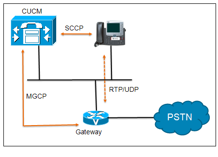
MGCP is a client/server protocol that allows the call agent (CA) to take control of a specific gateway endpoint (port). MGCP has the advantage of centralized gateway administration in the CUCM. CUCM controls the state of each port on the gateway endpoint .MGCP gateway can be controlled on a per endpoint (TDM port) level but H.323 and SIP cannot.
Note: MGCP gateway must be supported in CUCM. Use the Cisco software advisor Tool to make sure that the platform and version of Cisco IOS software or Cisco Catalyst Operating system is compatible with MGCP for CUCM.
MGCP Gateway Support
MGCP support in CUCM includes a wide range of analog and digital interfaces that can be used ton several Cisco router and switch platforms. FXO, FXS, T1-CAS, T1-PRI, E1-CAS, E1-PRI but some voice ports are not supported by MGCP say, E&M voice ports. CUCM pushes the Cisco IOS MGCP gateway configuration from the Cisco TFTP server to the gateway when automatic configuration is configured.
CUCM also supports Q.931 backhaul. Q.931 backhaul is only supported on ISDN voice ports. MGCP backhaul allows CUCM to process the Q.931 messaging from the ISDN circuit. The gateway router encapsulates the Q.931 signaling from the gateway over TCP port 2727
Q.931 Backhaul
Q.931 backhaul is a reliable TCP transport layer TCP/IP connection between CUCM and Cisco MGCP gateway. Q.931 backhaul is an encapsulation of the Q.931 signaling in the D channel of the ISDN TDM interface. Q.931 backhaul carries the raw Q.931 signaling to CUCM to be processed natively. The Gateway is still responsible for the termination of the Layer 2 Q.921 Link Access Protocol D-Channel (LAPD) signaling, but all ISDN layer 3 call setup/call tear down signaling (Q.931) is sent to CUCM for processing.
MGCP Call Flow
MGCP Gateway Configuration
1. MGCP Gateway Configuration: CUCM
Follow these steps to add an MGCP gateway to CUCM:
1a. Add an MGCP Gateway to CUCM
Step1: In CUCM Administration, Choose Device > Gateway.
Step2: Click the Add New button.
Step3: Choose the Appropriate MGCP gateway by gateway or router name
[ Gateway Type * - Cisco IAD2400/Cisco 1751/Cisco 1760/Cisco 1861/Cisco 269x/Cisco 26xx/Cisco 2801/Cisco 2811/Cisco 2821/Cisco 2821/Cisco 2851/Cisco 2901/Cisco 2811/Cisco 2821/Cisco 2851/Cisco 2901/Cisco 2911/Cisco 2921/Cisco 2951/Cisco 362x/Cisco 364x/Cisco 366x/Cisco 3725/Cisco 3745 etc)
Say in this case, Gateway Type: Cisco 2811
Step4: Click Next.
Step5: Choose MGCP from the protocol drop-down menu and click Next
MGCP Gateway Configuration
Sample MGCP gateway configuration displayed on the CUCM Page:
Select the type of gateway you would like to add: Gateway Type Cisco 2811 Protocol * - options are MGCP / SCCP
In this case for MGCP gateway, select MGCP as the Protocol |
Then the Configuration of the MGCP gateway includes the following steps:
Step1: Enter the host name or fully qualified domain name (FQDN) of the gateway in the Domain name field. If a domain name is specified in the Cisco router you must provision an FQDN. If the FQDN specified in the CUCM does not match the “host name” dot “domain name” of the Cisco IOS router, then end pint will never register. A router with the host name of Router1 and domain name of highpoint.com would have an FQDN of Router1.highpoint.come
Step2: Enter a description of the gateway.
Step3: Select a CUCM group
Step4: Configure the ISDN switch type
Step5: Locate the configured slots, VICS and endpoint selection, and select the voice hardware module placed in the slot
Step6: Click Save. Reset the gateway ( or click Apply config) for the changes to apply.
MGCP Gateway Configuration
Sample MGCP gateway configuration displayed on the CUCM Page:
Gateway Details Product: Cisco 2811 Protocol: MGCP Domain Name * : HQ-1 Description: HQ-1 headquarters MGCP gateway Cisco Unified Communications Manager Group*: Default
Configured slots, VICs and Endpoints Module in Slot 0 Module in Slot 1 (To add modules refer the next section “Endpoint module configuration”
Product specific configuration layout Global ISDN Switch type: 4ESS Switchback Timing* Graceful Type of DTMF Relay* Current GW config Modem Passthrough* Enable |
1b. Adding the Endpoints
Endpoints are added by selecting the Voice modules and voice interface cards at the Gateway configuration page. To add endpoints to a gateway, follow these steps:
Step1: Locate the configured slots, VICs and Endpoints selection and select the voice hardware module placed in the slot.
Step2: The subunits (VIC slots) of the selected voice module will display. Select the subunit (voice interface card)
Step3: Click Save.
Step4: Repeat the process to indicate all the voice interface cards on the gateway.
Endpoint configuration
Configured Slots, VICs and Endpoints Module in Slot 0 NM-4VWIC-MBRD Subunit 0: None Subunit 1: VWIC2-1MFT-T1E1-E1 [In this case Port no. would be: 0/1/0 ] Subunit 2: None Subunit 3: None Module in Slot 1 None
Note: Cisco IOS Command “Show diagnostic” will display the voice modules and voice interface cards (VIC) with which the gateway is equipped. |
To configure MGCP endpoint, follow these steps:
Step1: Click the endpoint identifier (0/1/0)
Step2: Select the device protocol or signaling for the endpoint. T1 and E1 interfaces support channel associated signaling (CAS) or common channel signaling (CCS) if the interface is an ISDN Primary Rate Interface (PRI). Analog interface supports ground –start (GS) and loop-start (LS) signaling. Select the signaling mechanism that be used on the endpoint and click Next.
Step3: Enter a description for the point.
Step4: Select the device pool for the endpoint.
Step5: Choose the Calling Search Space (CSS) and Significant digits under the Inbound Call routing section.
Step6: Click Save. Click Reset to rest the gateway. The reset functionality will push configuration changes to the gateway.
MGCP Endpoint configuration
Sample MGCP Endpoint configuration, from the CUCM administration page
Device Information Product: Cisco MGCP E1 Port Gateway: HQ-1 Device Protocol: Digital Access PRI End Port Name* S0/SU1/DS1-0@HQ-1 Description S0/SU1/DS1-0@HQ-1 Device Pool* Default Location Hub_None Enable : PSTN Access
Interface information PRI Protocol Type* PRI EURO QSIG Variant* No changes Protocol side* User Channel selection order* Bottom up PCM Type* A-law |
2. MGCP Gateway configuration: Cisco IOS Configuration
Only the two following commands are required to configure an MGCP gateway. Assume the TFTP server IP address is 192.168.1.200
ccm-manager config
ccm-manager config server 192.168.1.200
Prerequisites: For the configuration to work, the following prerequisites must be met.
- MGCP Gateway and the CUCM TFTP server must have IP connectivity between each other. It’s important to ensure that TCP and UDP ports 2427, 2428 and 2727 can communicate between the MGCP gateway and CUCM TFTP server. If there is a firewall then ensure these ports are enabled.
- MGCP gateway and endpoints are configured in CUCM. Configuration has been saved and the Reset have been applied.
- Host name or fully qualified domain name (FQDN) of the Cisco IOS MGCP gateway much match the CUCM MGCP gateway configuration. If the router’s running configuration file has the <ip domain-name> command in it, an FQDN must be used , example : router1.highpoint.com
Callmanager MGCP ports:
- CCM to gateway — uses src and destination UDP port 2427 (vice versa)
It means all the MGCP messages ( CRCX, MDCX, DLCX etc ) are carried over port 2427 from CUCM to gateway.
- From gateways to Call Agent uses UDP port 2727
- From Call Agent to gateways uses UDP port 2427
- Gateway to CCM – Keepalive and backhaul port – TCP port 2428.
It means NTFY keepalive messages and q931 backhauled messages are carried over 2428
2a. Configuring MGCP Gateway Registration
Configuring MGCP Gateway Registration
Controller E1 0/3/0 framing crc4 linecode hdb3 pri-group timeslots 1-31 service mgcp ! Interface serial0/3/0:15 isdn switch-type primary-4ess isdn incoming-voice voice isdn bind-13 ccm-manager ! ccm-manager mgcp ccm-manager music-on-hold ! mgcp mgcp call-agent 10.1.1.1 2427 service-type mgcp version 0.1 mgcp rtp unreachable timeout 1000 action notify mgcp modem passthrough voice mode nse mgcp package-capability rtp-package mgcp package-capability sst-package mgcp package-capability pre-package no mgcp package-capability res-package no mgcp package-capability fxr-package no mgcp timer receive-rtcp mgcp sdp simple mgcp rtp payload-type g726r16 static ! |
MGCP Gateway: Registration Verification
Verifying MGCP Gateway Registration
Verifying MGCP Gateway Registration
Router# show ccm-manager MGCP domain name : Router
Priority Status Host Primary Registered 10.16.240.124 First Backup None Second Backup None Current active Call Manager: 10.16.240.124 Backhaul/Redundant link port: 2428 Failover Interval: 30 seconds Keepalive Interval: 15 seconds Last keepalive sent: 00:45:31 (elapsed time: 00:00:04) Last MGCP traffic time: 00:45:31 (elapsed time: 00:00:04) Last failover time: None Switchback mode: Graceful MGCP fallback mode: Not selected Last MGCP Fallback start time: 00:00:00 Last MGCP Fallback end time: 00:00:00 PRI Backhaul Link info Link Protocol: TCP Remote Port Number: 2428 Remote IP Address: 10.16.240.124 Current Link State: OPEN Statistics: Packets recvd: 32 Recv failures: 0 Packets xmitted: 32 Xmit failures: 0 PRI Ports being backhauled: Slot 1, port 0 ! Configuration Auto-Download information No configurations downloaded Current State: Automatic Configuration Download feature is disabled Configuration Error History: FAX mode: cisco |
Verifying Endpoint Registration
Verifying Endpoint Registration
Router# show mgcp endpoints Interface T1 1/0 ! ENDPOINT-NAME V-PORT SIG-TYPE ADMIN S1/ds1-0/1@AV-2620-4 1/0:23 none UP S1/ds1-0/2@AV-2620-4 1/0:23 none UP S1/ds1-0/3@AV-2620-4 1/0:23 none UP S1/ds1-0/4@AV-2620-4 1/0:23 none UP S1/ds1-0/5@AV-2620-4 1/0:23 none UP S1/ds1-0/6@AV-2620-4 1/0:23 none UP S1/ds1-0/7@AV-2620-4 1/0:23 none UP S1/ds1-0/8@AV-2620-4 1/0:23 none UP S1/ds1-0/9@AV-2620-4 1/0:23 none UP S1/ds1-0/10@AV-2620-4 1/0:23 none UP S1/ds1-0/11@AV-2620-4 1/0:23 none UP S1/ds1-0/12@AV-2620-4 1/0:23 none UP S1/ds1-0/13@AV-2620-4 1/0:23 none UP S1/ds1-0/14@AV-2620-4 1/0:23 none UP S1/ds1-0/15@AV-2620-4 1/0:23 none UP S1/ds1-0/16@AV-2620-4 1/0:23 none UP S1/ds1-0/17@AV-2620-4 1/0:23 none UP S1/ds1-0/18@AV-2620-4 1/0:23 none UP S1/ds1-0/19@AV-2620-4 1/0:23 none UP S1/ds1-0/20@AV-2620-4 1/0:23 none UP S1/ds1-0/21@AV-2620-4 1/0:23 none UP S1/ds1-0/22@AV-2620-4 1/0:23 none UP S1/ds1-0/23@AV-2620-4 1/0:23 none UP |
Fractional T1/E1 Configuration on CUCM
To put specific time slots of an MGCP T1 or E1 PRI into the maintenance state, you need to retrieve the MGCP endpoint ID, example : S0/SU1/DS1-0@HQ-1 and select the Enable status Poll check box in the interface information configuration section on the MGCP endpoint configuration page.
From the CUCM Administration, choose System > Service Parameter and then choose the Cisco Call Manager Service from the Service drop-down menu. Click the Advanced button at the top of the configuration page to view hidden advanced configuration options on the MGCP gateway that are required to change the B-Channel Maintenance status parameter.
This parameter allows CUCM to change the individual B-Channel maintenance state for the time slots on the T1/E1 interface.
Verifying T1/E1 Controller Status
Rourter # show controller e1
- E1 status should be UP.
- E1 should be Channelized E1 – balanced , 120 ohms
- No Alarms Detected.
Verifying T1/E1 Controller status
HQ-1 # show controller e1
E1 7/0 is up. Applique type is Channelized E1 - balanced Description: E1 from Idea No alarms detected. alarm-trigger is not set Version info of slot 7: HW: 1032, PLD Rev: 7 Framer Version: 0x9
Manufacture Cookie Info: EEPROM Type 0x0001, EEPROM Version 0x01, Board ID 0x03, Board Hardware Version 4.8, Item Number 73-3996-05, Board Revision A1, Serial Number JAE1125M7VQ, PLD/ISP Version <unset>, Manufacture Date 24-Jun-2007.
Framing is NO-CRC4, Line Code is HDB3, Clock Source is Line. Data in current interval (770 seconds elapsed): 0 Line Code Violations, 0 Path Code Violations 0 Slip Secs, 0 Fr Loss Secs, 0 Line Err Secs, 0 Degraded Mins 0 Errored Secs, 0 Bursty Err Secs, 0 Severely Err Secs, 0 Unavail Secs Data in Interval 1: 0 Line Code Violations, 0 Path Code Violations 0 Slip Secs, 0 Fr Loss Secs, 0 Line Err Secs, 0 Degraded Mins 0 Errored Secs, 0 Bursty Err Secs, 0 Severely Err Secs, 0 Unavail Secs Data in Interval 2: 0 Line Code Violations, 0 Path Code Violations 0 Slip Secs, 0 Fr Loss Secs, 0 Line Err Secs, 0 Degraded Mins 0 Errored Secs, 0 Bursty Err Secs, 0 Severely Err Secs, 0 Unavail Secs Data in Interval 3: 0 Line Code Violations, 0 Path Code Violations 0 Slip Secs, 0 Fr Loss Secs, 0 Line Err Secs, 0 Degraded Mins 0 Errored Secs, 0 Bursty Err Secs, 0 Severely Err Secs, 0 Unavail Secs Data in Interval 4: 0 Line Code Violations, 0 Path Code Violations 0 Slip Secs, 0 Fr Loss Secs, 0 Line Err Secs, 0 Degraded Mins 0 Errored Secs, 0 Bursty Err Secs, 0 Severely Err Secs, 0 Unavail Secs Data in Interval 5: 0 Line Code Violations, 0 Path Code Violations 0 Slip Secs, 0 Fr Loss Secs, 0 Line Err Secs, 0 Degraded Mins 0 Errored Secs, 0 Bursty Err Secs, 0 Severely Err Secs, 0 Unavail Secs |
Verifying T1/E1 Interface status
An easy way to check the operation of an MGCP controlled T1/E1 ISDN PRI interface is by using the
# show isdn-status command and checking the Layer1 and Layer2 status as demonstrated here.
The Layer 2 status of MULTIPLE_FRAME_ESTABLISHED is normally what you’re looking for here. This message indicates the Layer 1 (T1/E1 controller) functionality is active and Layer 2 (Q.921 LAPD signaling)communication between the carrier equipment and the Cisco router is operational. Any layer 2 status other than MULTIPLE_FRAME_ESTABLISHED normally indicates a problem with Layer 1 and/or Layer 2 communication
Verifying T1/E1 Interface status
Router# show isdn status
HQ-1 # show isdn-status
Global ISDN Switchtype = primary-net5
ISDN Serial 0/1/0:15 interface ds1 0, interface ISDN Switchtype = primary-net5 Layer 1 Status: ACTIVE Layer 2 Status: TEI = 0, Ces = 1, SAPI = 0, State = MULTIPLE_FRAME_ESTABLISHED Layer 3 Status: 0 Active Layer 3 Call(s) Active dsl 0 CCBs = 0 The Free Channel Mask: 0xFFFF7FFF Number of L2 Discards = 746, L2 Session ID = 4 Total Allocated ISDN CCBs = 0 |
Related Information
- Mark as Read
- Mark as New
- Bookmark
- Permalink
- Report Inappropriate Content
hey thanks for this howto,what about route calls to the mgcp gateway,how it work and configure it un the cucm ?
- Mark as Read
- Mark as New
- Bookmark
- Permalink
- Report Inappropriate Content
Hi Abderrahmane
Please refer the following sections in the gateway to complete your mgcp gateway and CUCM configuration. I have given the procedures.
1. MGCP Gateway Configuration
2. MGCP Gateway Configuration : Cisco IOS Configuration
Your comments are very generic, if you are looking for any specific information, please revert. Thanks
- Mark as Read
- Mark as New
- Bookmark
- Permalink
- Report Inappropriate Content
hi,how to configure MGCP Route Pattern my goal is to route external PSTN number to the gateway ,and if we have many device pool so we have to create the same getway for every device pool ?
thanks
- Mark as Read
- Mark as New
- Bookmark
- Permalink
- Report Inappropriate Content
Hi Abderrahmane
Yes, You can create mutliple device pool for the Head quaraters and Branches, say Branch1, Branch2 and you can create the Gateway for each location using protocol type MGCP. You have to map the Gateway only in your route pattern configuration and you can route the calls towards the PSTN network through the gateway. For that,
Configure the Call routing paramater : Go to Cisco unified CM> Call Routing > Route/hunt > Route pattern
Define the Router pattern : say 98400xxxxx along with the Partition and mention the respective gateway name.
Hope this information is useful. Thanks.
- Mark as Read
- Mark as New
- Bookmark
- Permalink
- Report Inappropriate Content
thanks a lot that was helpfull for me.
- Mark as Read
- Mark as New
- Bookmark
- Permalink
- Report Inappropriate Content
Hi ,
what if we change the switch type from 4ESS to Primary-qsig ? does the configuration still valid ?
- Mark as Read
- Mark as New
- Bookmark
- Permalink
- Report Inappropriate Content
Nice work!
- Mark as Read
- Mark as New
- Bookmark
- Permalink
- Report Inappropriate Content
21:50:26: send_mgcp_msg, MGCP Packet sent --->
NTFY 41 aaln/S1/SU0/1@c26001.atl0.cisco.com MGCP 0.1
N: mgcp.aSCT1CA.atl0.cisco.com:2427
X: 50
O: L/hd
MGCP Pocket Shared
- Mark as Read
- Mark as New
- Bookmark
- Permalink
- Report Inappropriate Content
O: L/hd
DECODE
NTFY 41
!--- This is the notify (NTFY) message sent to the call agent to report !--- an observed event. The number 41 is the notify sequence number.
aaln/S1/SU0/1@c26001.atl0.cisco.com
!--- This is the MGCP endpoint ID.
MGCP Pocket Notified
- Mark as Read
- Mark as New
- Bookmark
- Permalink
- Report Inappropriate Content
MGCP 0.1
!--- The MGCP version is 0.1.
N: mgcp.aSCT1CA.atl0.cisco.com:2427
!--- This is the notified entity ID with destination !--- User Datagram Protocol (UDP) port number.
X: 50
MGCP Version Shared
- Mark as Read
- Mark as New
- Bookmark
- Permalink
- Report Inappropriate Content
X: 50
21:50:26: MGCP Packet received <---
200 41 OK
- Mark as Read
- Mark as New
- Bookmark
- Permalink
- Report Inappropriate Content
Excellent document! there are a lot of stuff that you explain perfectly than other sources.
Find answers to your questions by entering keywords or phrases in the Search bar above. New here? Use these resources to familiarize yourself with the community: