- Cisco Community
- Technology and Support
- Data Center and Cloud
- Data Center and Cloud Knowledge Base
- Configure ACE in Direct Server Return mode
- Subscribe to RSS Feed
- Mark as New
- Mark as Read
- Bookmark
- Subscribe
- Printer Friendly Page
- Report Inappropriate Content
- Subscribe to RSS Feed
- Mark as New
- Mark as Read
- Bookmark
- Subscribe
- Printer Friendly Page
- Report Inappropriate Content
02-06-2012 04:03 AM - edited 08-29-2017 04:52 AM
- Introduction
- Direct Server Return
- SYN Flood Protection in DSR environment
- Configure DSR on ACE
- Troubleshoot
- Related Information
Introduction
Direct Server Return (DSR) is a technique that can greatly augment the overall throughput of the server load-balancing infrastructure, but it comes with a few catches. With DSR the initial request from the clients traverse the load-balancer to get load-balanced to a real server; but unlike a traditional deployment the server directly responds to the client's IP address bypassing the load-balancer. As many protocols today involve a few packets from the client and many packets from the server, the net effect of DSR is the acceleration of server to client communication. By using DSR in conjunction with powerful servers connected to a LAN switch such as the Catalyst 6500, scaling to tens or even hundreds of gigabits per second is totally feasible.
Direct Server Return
Conceptually, DSR only exists on ACE and the real servers. Clients know nothing about DSR. When operating in DSR mode, the ACE module does not perform any network address translation (NAT) when receiving a packet destined to a VIP. Traffic from the client hits the virtual IP but contrary to a non-DSR scenario ACE forwards the packet to the one of the real servers using the VIP as the destination IP address. Naturally, if a real server is to pick this up the packet must be sent to its MAC address. That is exactly what ACE does: it rewrites the destination MAC address to that of a real server, but leaves the destination IP unchanged.
A few extra server-side configuration steps are necessary to make this work:
1. Real servers have to be configured with a virtual interface. The virtual interface is sometimes referred to as a "loopback interface".
2. That virtual interface has the IP address of the VIP.
3. The virtual interface must not respond to ARP requests. This is required to make SYN cookies work and protect against SYN flood.
While points number 1 and 2 are pretty straight forward, point number 3 might be a critical component to get DSR to work properly depending on the topology. Figure 1 helps clarify the reason behind this. It shows a typical DSR network topology where the VIP address is totally unrelated to the real servers' IP addresses, thereby totally obfuscating the internal IP addressing scheme.
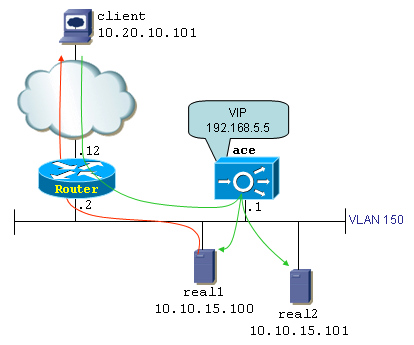
The topology consists in a client (10.20.10.101), a router, an ACE module and two real servers: 10.10.15.100 and 10.10.15.101. Both servers are grouped in a server farm represented by VIP 192.168.5.5. Note that the router and ACE do not share the 192.168.5.x subnet, only ACE knows about it. The router and ACE are on the 10.10.15.0/24 subnet. When the client connects to 192.168.5.5, its packets hit the router.
Two configurations are possible on the router so it can forward traffic to the VIP:
1. a static route to 192.168.5.5 via 10.10.15.1
2. a secondary IP address on the 192.168.5.x subnet
Option 1 is the most straightforward method and should be the preferred one; it is what we will use in this document. Option 2 comes with a slight twist: it is required that the servers do not answer ARP requests for the VIP address. With option 2 the router directly ARPs for 192.168.5.5 because it has itself a leg in the 192.168.5.x subnet. A race condition occurs: either real server could reply to the ARP request faster than ACE, instantly breaking the server load-balancing scheme as the ACE module would be bypassed for client-to-server traffic. With option 1 on the other hand, the router forwards traffic destined to 192.168.5.5 to the MAC address of the ACE module. It just has no reason to ARP for 192.168.5.5
With these things clear lets have a look at the limitations of using DSR:
a) L4 only: DSR is a Layer-4 only feature. This is not an ACE specific limitation. The load-balancer does not participate in both legs of bi-directional client/server communications. Therefore, features that require "proxying" the communication are not applicable to DSR environments. Some features that are incompatible with DSR are HTTP header parsing, HTTP header insert, Cookie sticky, SYN cookies, etc.
b) Connection timeouts: Because ACE only sees one leg (client-server) of each connection, it can't tell whether a connection has ended - keep in mind that TCP is full-duplex, so the presence of a FIN in one direction doesn't mean ACE should tear down the entire connection. Therefore, connections simply age out after a user-configurable idle timeout. The default connection timeouts are
TCP - 3600 seconds
UDP - 120 seconds
ICMP - 2 seconds
c) Topological considerations: Real servers must be "Layer-2 adjacent" to the load-balancer when running in DSR mode. That is because the load-balancer simply performs a destination MAC address rewrite, and the rewritten MAC is always one that belongs to a real server. Looking at figure 1, real servers must be placed on VLAN 150. You cannot insert a routed hop between ACE and the real servers.
d) Server side consideration: A new virtual interface has to be created on the real servers for each VIP that exists on the load-balancers. As explained previously, depending on the topology you may have to configure ARP suppression on the servers - a configuration task that can range from trivial to tricky depending on the server's operating system.
SYN Flood Protection in DSR environment
A fairly common network attack called SYN Flood consists in sending a large amount of TCP segments with the SYN flag set to a victim. The attacker hopes to saturate the victim with so many new connection requests that it can't process new connections anymore, resulting in a denial of service condition. The attack scenario very often spoofs the source IP addresses used to initiate connection requests, making servers reply with SYN-ACK to innocent hosts that haven't asked for anything. Those innocent bystanders in turns don't respond with an ACK, leaving the server with way too many half-open connections that are just sitting there waiting to time out.
In order to prevent a SYN flood, the load-balancer inserts itself in the 3-way handshake process. Upon receiving a SYN segment, the load balancer responds with a SYN-ACK on behalf of the server using its own sequence number y. The number y is derived from the sequence number contained in the incoming SYN segment, the client's MSS, the 4-tuple and a cryptographic function that takes a clock value into account. If the client address isn't spoofed and the client's request is legitimate, the odds are high that an ACK segment will come back to the load balancer. That ACK should contain sequence number y+1. The load balancer can then verify whether this ACK is indeed a valid response to the original SYN-ACK's sequence number y it had sent out. If it does, the client is "authentic" and at that point the load balancer initiates a connection to the server on behalf of the client by transforming the client's ACK into a spoofed SYN that uses the client's IP address.
A common protection mechanism against this attack is provided through an algorithm called SYN Cookies. Unfortunately SYN cookies can't operate in a DSR environment because once the load balancer sends the spoofed SYN to the server on behalf of the client, the response from the server does not cross the load balancer anymore. That response is a SYN + ACK segment containing a totally new initial sequence number. Because of the asymmetric nature of DSR environments, the server directly responds to the client with a SYN that contains a totally new and random initial sequence number, and an ACK which is unrelated to previous segments. The client wants neither of those because it has already (or at least it believes it has, because in reality the load balancer spoofed it) received a SYN + ACK from the server. Because this new SYN + ACK isn't a duplicate entry nor related to the existing connection, the client tears down the connection by sending a RST segment.
Configure DSR on ACE
In order to configure ACE for DSR, two specific configuration steps are required:
1. Configure the server farm in transparent mode
2. Disable the TCP/IP normalizer on the client-side interface
The first step (transparent server farm) simply tells ACE to not perform NAT of the VIP address to a real server address. The second step turns off ACE's "statefulness" - it lets ACE accept client-originated TCP ACKs and data without having seen a full 3-way handshake before that. Remember that with DSR the servers respond directly to the client, bypassing ACE. The clients however always end up crossing ACE to reach the servers. Therefore, this results in a certain traffic asymmetry that is taken care of by disabling the TCP/IP normalizer on ACE.
Here is the configuration as it appears on ACE:
access-list inbound line 10 extended permit ip host 10.20.10.101 host 192.168.5.5
rserver host real1
ip address 10.10.15.100
inservice
rserver host real2
ip address 10.10.15.101
inservice
serverfarm host farm1
transparent
rserver real1
inservice
rserver real2
inservice
class-map match-all vip
2 match virtual-address 192.168.5.5 any
policy-map type loadbalance first-match lbpol
class class-default
serverfarm farm1
policy-map multi-match LBPOL
class vip
loadbalance vip inservice
loadbalance policy lbpol
loadbalance vip icmp-reply active
interface vlan 150
description server-side
ip address 10.10.15.1 255.255.255.0
no normalization
access-group input inbound
service-policy input LBPOL
no shutdown
ip route 0.0.0.0 0.0.0.0 10.10.15.2
Configure Virtual Interface on Server
On a server configuration of virtual interface is simple. Here is an example of Linux server.
[root@linux-p root]# ifconfig eth1:1
eth1:1 Link encap:Ethernet HWaddr 01:00:CA:FE:00:00
inet addr:192.168.5.5 Bcast:10.10.15.255 Mask:255.255.255.255
UP BROADCAST RUNNING MULTICAST MTU:1500 Metric:1
Interrupt:10 Base address:0xdc00
[root@linux-p root]# ifconfig eth1
eth1 Link encap:Ethernet HWaddr 01:00:CA:FE:00:00
inet addr:10.10.15.101 Bcast:10.10.15.255 Mask:255.255.255.0
inet6 addr: fe80::200:caff:fefe:0/64 Scope:Link
inet6 addr: 2001:db8:250::121/64 Scope:Global
UP BROADCAST RUNNING MULTICAST MTU:1500 Metric:1
RX packets:4630 errors:118 dropped:0 overruns:0 frame:99
TX packets:342 errors:1 dropped:0 overruns:0 carrier:4
collisions:0 txqueuelen:100
If ARP suppression is required, use this step (optional):
[root@linux-p root]# ip link set eth1:1 arp off
Troubleshoot
In case the setup does not work try the following settings on your Windows server. Open CMD and enter the following commands:
netsh interface ipv4 set interface "HLB-VIP" weakhostreceive=enabled
netsh interface ipv4 set interface "HLB-VIP" weakhostsend=enabled
netsh interface ipv4 set interface "Local Area Connection" weakhostreceive=enabled
From Windows Control Panel do the following:
1. Open Device manager (right click "Computer" and click "Manage")
2. Click on "Device Manager"
3. Expand "Network Adapters"
4. Right click your network adapter
5. click "properties"
6. click the tab named "Advanced"
7. Find "IP Checksum Offload" and click it
8. Put the value to the right to "Disabled"
9. Find "TCP Checksum offload (IPvX)
10. Set the value to the right to "Disabled"
Also try to update the drivers for the server NIC card to resolve any issue.
Related Information
- Mark as Read
- Mark as New
- Bookmark
- Permalink
- Report Inappropriate Content
Cisco has a new solution called ITD:
http://blogs.cisco.com/datacenter/itd-load-balancing-traffic-steering-clustering-using-nexus-5k6k7k
ITD (Intelligent Traffic Director) is a hardware based multi-Tbps Layer 4 load-balancing, traffic steering and clustering solution on Nexus 5K/6K/7K series of switches. It supports IP-stickiness, resiliency, NAT, (EFT), VIP, health monitoring, sophisticated failure handling policies, N+M redundancy, IPv4, IPv6, VRF, weighted load-balancing, bi-directional flow-coherency, and IPSLA probes including DNS. There is no service module or external appliance needed.
- Mark as Read
- Mark as New
- Bookmark
- Permalink
- Report Inappropriate Content
Whenever the clients are pinging to the server which is located behind LB must reply with Server real IP address. But instead of that LB is replaying with the VIP.
As per our security audit advice our customer wanted to change this and we would like to know is there any settings available in LB side to make reply packet forwarded with real server IP address Instead of LB VIP. “
- Mark as Read
- Mark as New
- Bookmark
- Permalink
- Report Inappropriate Content
Sandeep, very good explanation.
Find answers to your questions by entering keywords or phrases in the Search bar above. New here? Use these resources to familiarize yourself with the community: