I come across lot of questions on ACI fabric access policies and steps involved in on-boarding a physical server into ACI. While there are lots of helpful documents available online, which are based on Cisco Official ACI configuration guides, still it is tough for a novice (sometimes even experienced ones) to break down these exhaustive steps and really understand every component.
I would like to share with you a simple workflow followed by me to on-board any physical server and firmly believe, it would be helpful for everybody starting their ACI Journey.
There are two sections basically:
- Fabric – That governs your physical access policies (Physical Network)
- Tenant – That governs your overlay policies (Logical Construct)
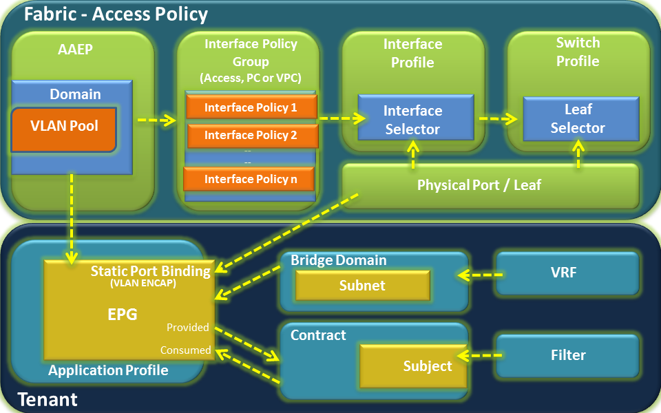
Below diagram represents all various components of Fabric & Tenant sections and shows how they form relations with each other and stitched together.

Fabric – Access Policy
Let’s begin with Fabric part of the configuration:
Go to Fabric tab > Access Policies and look at the options on left pane from bottom. NEVER Start from the top.
Below are the config steps with GUI path navigation details.
Step 1: Create a static VLAN Pool
So basically you define what vlan id you will be using on your interface to on-board the server.
Fabric > Access Policies > Pools > VLAN -- Right click and Create Vlan Pool
Step 2: Create Physical Domain and bind VLAN Pool to the domain
Fabric > Access Policies > Physical and External Domains > Physical Domains – Right click and Create Physical Domain
Just give name for the physical domain and attach the Vlan pool created in step 1. Leave the Associated Attachable Entity Profile option blank, we will do that in next step.
Step 3: Create AAEP and bind domain to the AAEP
Fabric > Access Policies > Global Policies > Attachable Access Entity Profile – Create Attachable Access Entity Profile and just attach your physical domain created in step 2 here.
Step 4: Create Interface Policies
These are nothing but generic configs that you would want on your interface like cdp on, lldp off, speed, duplex, bpdu filter etc. Policies created here is an one time process and are reused extensively in future while on-boarding new servers.
Fabric > Access Policies > Interface Policies >Policies – Expand this and you will find all different parameters and their possible attributes
Select whatever is applicable for your servers. Common ones are cdp, link level, lldp, Port-Channel(LACP modes).
Step 5: Create Interface Policy Group
Select what all policies created in step 4 need to be activated on the interface
Fabric > Access Policies > Interface Policies > Leaf Policy Group – Right click and create policy group based on interface type(PC, VPC or access)
You can select policies through drop down menu here. This is the place where you also attach the AAEP created in step 3.
Step 6: Create Leaf Profiles
Here you select the interfaces and attach policy group created in step 5
Fabric > Access Policies > Interface Policies >Profiles > Leaf Profiles – Right Click and create leaf interface profile, create interface selector (where you define interface name and attach interface policy group)
Step 7: Create Switch Profile
Finally, you select the switches here, where exactly the servers are connected. Everything done till step 6 is just an abstract and when you bind leaf interface profile created in step 6 to the switch profile then the config is actually completed and makes sense.
Fabric > Access Policies >Switch Policies > Profiles – Right click and create leaf profile, select leaf switches (keep the policy group option empty if there is no specific global config required at leaf level), then move to the associated interface selector profiles and select the leaf interface profile created in leaf selector option and attach the interface policy group.
Phew!!! That completes our switch interface configuration required to on-board the server. But since we are in ACI, there are few more things to do before we are done.
Any server (physical or virtual) we on-board in ACI has to be part of an application EPG, as everything is policy driven in ACI and to write policies you need to have classification of services.
Tenant Side Configuration:
So we need to go to the respective tenant where that sever belongs to and perform following steps:
Step1: Create a VRF
Tenant > Networking > VRF – Right click and create VRF
Step2: Create a Bridge Domain
Tenant > Networking >Bridge Domain – Right click and create a Bridge Domain
You need to associate your BD with the VRFand create the subnet (which will be the distributed gateway for your server)
Step 3: Create Application Profile
Tenant > Application Profile – Right click and create an Application profile
Application profile is nothing but a container for the EPGs.
Step 4: Create an Application EPG
Tenant > Application Profile > expand respective application profile and right click on Application EPG and Create Application EPG
You will have to associate BD while creating EPG, can keep remaining options as default.
Step 5: Attach Physical Domain to the EPG
Expand application EPG created in Step 4. You would see Domains option on left pane.That’s the place you need to attach your Physical domain option created in Step 2 of Fabric - Access Policy.
Step 6: Static port binding in EPG
Expand application EPG created in Step 4. You would see static port binding option. That’s where you provide the static path of the Leaf/Port configured for the server on Fabric – Access Policy. Also need to specify the vlan encap id from the vlan pool created in Step 1 of Fabric – Access Policy.
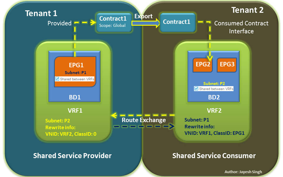
Step 7: Attach contract to the EPG
Contract is required for any endpoint in an EPG to communicate with another endpoint in a different EPG or external network (External EPG). Attach the contract as per communication direction (Source EPG will Consume and Destination EPG will Provide).
This completes the configuration required for connecting physical servers to Cisco ACI Fabric.
Hope that helps! Your feedback will be highly appreciated!
Regards,
Jayesh

")