- Cisco Community
- Technology and Support
- Data Center and Cloud
- Data Center and Cloud Knowledge Base
- Configuring VLANs on UCS and VMware
- Subscribe to RSS Feed
- Mark as New
- Mark as Read
- Bookmark
- Subscribe
- Printer Friendly Page
- Report Inappropriate Content
- Subscribe to RSS Feed
- Mark as New
- Mark as Read
- Bookmark
- Subscribe
- Printer Friendly Page
- Report Inappropriate Content
10-23-2012 07:49 AM - edited 03-01-2019 05:57 AM
- Introduction
- VLAN Configuration on UCS
- UCS disjoint L2 Consideration
- VLAN Configuration on VMware
- Related Information
Introduction
This document shows steps required to add VLANs to both UCS and VMware. In UCS each VLAN is identified by a unique ID. The VLAN ID is a number that represents that particular VLAN. The name that you assign to a VLAN ID adds a layer of abstraction that allows you to globally update all servers associated with service profiles that use the named VLAN. You can also create more than one named VLANs with the same VLAN ID. Note that the name of a VLAN is known only within the UCS environment, and outside of the UCS the VLAN is represented by the unique ID.
VLAN Configuration on UCS
Depending on how the UCS infrastructure is configured, VLAN availability for physical hosts may have to be configured on either a port group or individual host basis. The same applies in the VMWare environment.
Follow the steps to configure VLAN on UCS:
a) Open UCS manager. In the Navigation pane on the left of the application, select the LAN tab.
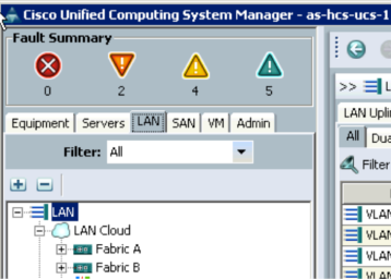
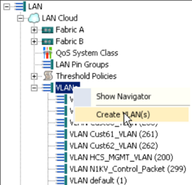
b) Expand the navigation tree so that the VLANs branch is visible. Right click on the VLANs branch and select Create VLAN(s).
c) Provide a meaningful name for the VLAN, this name can not be changed once saved. For most situations the Common/Global radio button should be selected to ensure the same configuration is applied to both Fabrics. Enter the VLAN ID(s), then press the Check Overlap button to ensure there is no conflict with existing configuration and if unique, press OK.

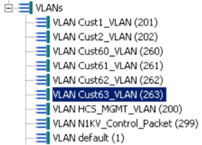
d) Check that the newly created VLAN appears in the list of configured VLANs in the navigation pane.
e) If the platform is using vNIC templates then the next step is to add the created VLAN to the required templates. Expand the vNIC Templates branch of the navigation pane (LAN -> Policies -> root -> vNIC Templates) and select the template which should have the VLAN available.

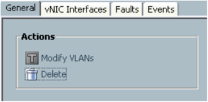
f) On the General tab for each Template click Modify VLANs.
g) In the window that opens add the new VLAN.

Repeat this for each Template.
h) Switch to the servers tab in the Navigation Pane and expand the Service Profiles and the root node, the service profiles for each Chassis/Blade should be visible.
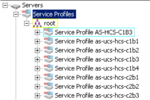
i) Expand each service profile in turn so that the vNIC for the Chassis/Blade is visible. If the vNIC is bound to one of the templates modified earlier then the VLAN will be listed under the vNIC.
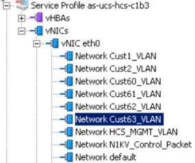
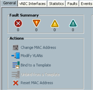
j) If the VLAN is not listed then select the vNIC and in the main panel click the Modify VLANs link. For vNICs bound to templates, this link will be greyed out.
k) In the window that opens select the new VLAN.
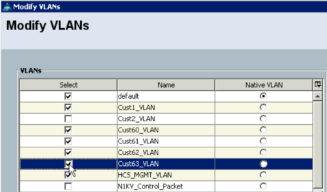
Repeat this process for each vNIC that is not bound to a template.
Once all the vNICs have the VLAN available to them, exit UCS Manager.
UCS disjoint L2 Consideration
From UCS End Host Mode perspective, a disjoint L2 (layer 2) is a network design in which UCS connects to different upstream switches (via single port or port-channel) and these upstream switches carry different non-overlapping vlans. This can also be same physical upstream switch but different vlans allowed on different switch ports.
Disjoint L2 features::
- Feature introduced in UCS version 2.x. By default, version 1.4 behavior is preserved (i.e all VLANs present in all uplinks)
- Native support in End-Host mode allows simplification of configuration (i.e no need for Switch mode)
- Overlapping VLANs are not supported
- Per VLAN broadcast/multicast listener
- Hardware independent feature (supported in 6100 and 6200 FI)
A more detailed description can be found in following whitepaper.
Deploy Layer 2 Disjoint Networks Upstream in End Host Mode
As per default behavior, UCS will allow all vlans on all uplink ports. In case of disjoint L2 setup, since upstream switches are not carrying all vlans, the default UCS behavior breaks connectivity for some hosts/VMs depending on pinning. This happens because either the VM is pinned to wrong uplink, which blackholes all the VM traffic; or the designated receiver for the vlan is chosen on wrong uplink, which presents issues with broadcast and multicast (eg ARP discovery).
Note that if using pin groups, you are taking care only of the first situation and not the second one.
In Disjoint L2 setup it is important to tag correct vlans to correct uplink ports. Following link describes how to do this in UCSM.
Assigning Ports and Port Channels to VLANs
VLAN Configuration on VMware
Follow these steps to add VLAN on VMware:
a) Open vSphere Client and connect to the VCENTER server. Navigate to the blade that the VLAN is required on (Home -> Inventory -> Hosts and Clusters). Expand the Navigation tree, to locate the server name and then select the Configuration tab in the main window. From within the Configuration window, select Networking.
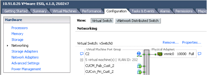
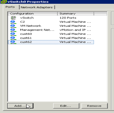
b) Click on the Properties link for the Virtual Switch, then in the opened window click on the Add button.
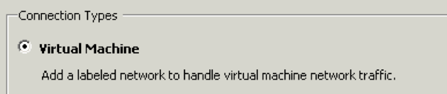
c) In the next window select Virtual Machine in the Connection Types and click next.
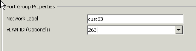
d) Under Port Group Properties enter a Network Label and the VLAN ID, then click Next.
e) Now the new VLAN should show under Host networking vSwitch, click Finish.

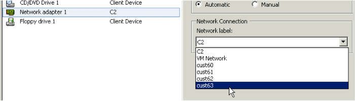
f) To add a virtual machine to the VLAN, edit the machine configuration, select the Network Adapter and from the Network Connection drop down list select the new VLAN.
Related Information
Understanding and Deploying UCS B-Series LAN Networking
VMWare ESXi 4.0 Installation on UCS Blade Server with UCS Manager KVM
- Mark as Read
- Mark as New
- Bookmark
- Permalink
- Report Inappropriate Content
what if that FI (B) goes down, I hope it will affect affect ESXI level vm's (cust63). am i correct?
- Mark as Read
- Mark as New
- Bookmark
- Permalink
- Report Inappropriate Content
Great post!!
thanks man for sharing your knowledge!!!
- Mark as Read
- Mark as New
- Bookmark
- Permalink
- Report Inappropriate Content
Document needs to be updated for more recent versions of UCS Manager. In UCS 3.1 is does not seem to be possible to modify the VLANs on vNIC templates once they have been assigned to an interface, all the options are greyed out. I don't know if this is a bug or a feature.
Find answers to your questions by entering keywords or phrases in the Search bar above. New here? Use these resources to familiarize yourself with the community: