- Cisco Community
- Technology and Support
- Data Center and Cloud
- Data Center and Cloud Knowledge Base
- Putting Overlay Transport Virtualization (OTV) to Work for You
- Subscribe to RSS Feed
- Mark as New
- Mark as Read
- Bookmark
- Subscribe
- Printer Friendly Page
- Report Inappropriate Content
- Subscribe to RSS Feed
- Mark as New
- Mark as Read
- Bookmark
- Subscribe
- Printer Friendly Page
- Report Inappropriate Content
08-17-2011 03:58 AM - edited 03-01-2019 05:54 AM
Introduction
Overlay Transport Virtualization (OTV) is a feature available on the Nexus 7000 series switches that enables extension of VLANs across Layer 3 (L3) networks. This enables new options of data center scale and design that have not been available in the past. The two common use cases include data center migration and workload mobility. Interestingly, many jump to a multiple physical data center scenario and start to consider stretched clusters and worry about data sync issues and while OTV can provide value in those scenarios it also is a valid solution inside the data center where L3 interconnects may segment the network but the need for mobility is present.
OTV in detail
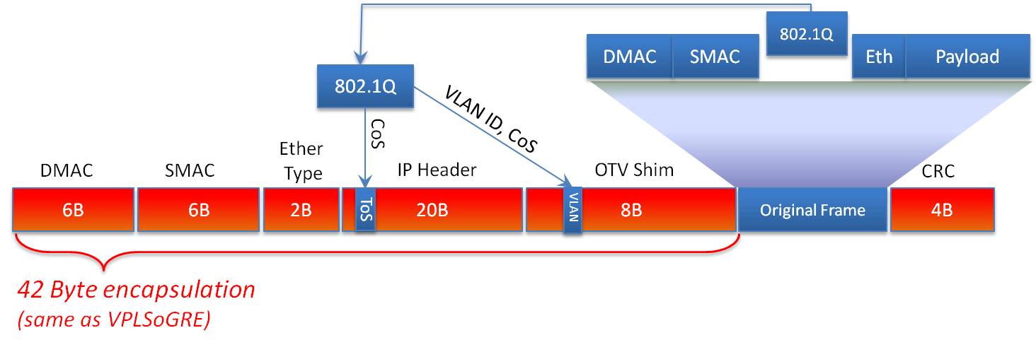
OTV is significant in its ability to provide this extension without the hassles and challenges associated with traditional Layer 2 extension, such as merging STP domains, MAC learning, and flooding. OTV is designed to drop STP BPDUs across the Overlay interface, which means STP domains on each side of the L3 network are not merged. This is significant in that it minimizes fate sharing where a STP event in one domain ripples to other domains. Additionally, OTV uses IS-IS at its control plane to advertise MAC addresses and provide capabilities such as loop avoidance and optimized traffic handling. Finally, OTV doesn't have state that needs maintained as is required with pseudo wire transports like EoMPLS and VPLS. OTV is an encapsulating technology, and as such, adds a 42 byte header to each frame transported across the Overlay.
Below is the frame format in more detail.
As mentioned earlier, OTV has the ability to minimize the amount of traffic that crosses the Overlay network in addition to blocking STP. One of the first techniques involves the way OTV advertises MAC addresses. In a traditional Ethernet network, MAC addresses are flooded throughout the network. This behavior isn’t desirable across a Data Center Interconnect (DCI) where bandwidth may be at a premium, so OTV doesn’t flood but rather advertises MAC addresses it learns and will forward traffic only to known addresses. This is particularly useful because, in some cases, Content Addressable Memory (CAM) and Address Resolution Protocol (ARP) tables can get out of sync. When this happens, switches will flood traffic out every port in the VLAN in the hopes of reaching the destination MAC. This is referred to as unicast flooding. OTV doesn’t participate in unicast flooding and, as such, saves precious DCI bandwidth.
Additionally, OTV has a feature referred to as ARP neighbor discovery where it will snoop ARP requests as they traverse the network. This enables the OTV device to then respond to ARP requests locally for devices it learns about across the overlay, which in turn preserves the DCI bandwidth.
OTV also has the ability to effectively multi-home and provide load balancing and redundancy in a simple manner. The way this is accomplished in OTV is by the use of the concept of a site VLAN. The site VLAN is a VLAN that's dedicated to OTV and NOT extended across the Overlay but is trunked between the two OTV edge devices. This VLAN doesn't need any IP addresses or SVIs created, it just needs to exist and be added to the OTV config as shown below.
otv site-vlan 99
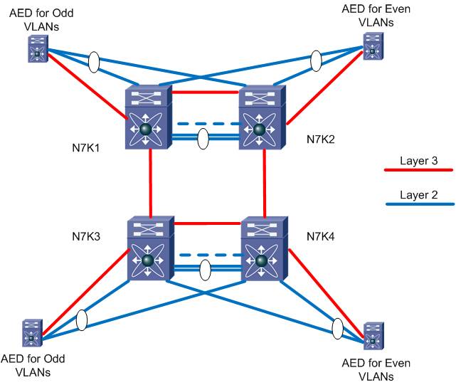
With the simple addition of this command, the OTV edge devices will discover each other locally and then use an algorithm to determine a role each edge device will assume on a per VLAN basis. This role is called the Authoritative Edge Device (AED). The AED is responsible for forwarding all traffic for a given VLAN including broadcast and multicast traffic. Today the algorithm aligns with the VLAN ID with one edge device supporting the odd numbered VLANs and the other supporting the even numbered VLANs. This is illustrated in the topology below.
Finally we’ll want to optimize our egress routing for the stretched VLANs so that we can have local devices make routing decisions. This is referred to as First Hop Redundancy Protocol (FHRP) localization. These protocols are Host Standby Routing Protocol (HSRP v1 and v2) Virtual Router Redundancy Protocol (VRRP), and Gateway Load Balancing Protocol (GLBP). These protocols allow two network devices to share a common IP address to be used as the default gateway on a subnet and provide redundancy and load balancing to clients in that subnet.
Before we can discuss FHRP localization, let's review why this might be significant to our design. Typically with FHRPs the members of the group are local to each other both logically and physically. Depending on the FHRP, there is load balancing or redirection between the devices to the "active" member to handle traffic. This works well when considered locally and most of us use it without a second thought.
When we start to stretch or extend our VLANs across distances, latency is introduced. While a 1ms one-way latency may not sound significant, when accumulated over a complete flow or transaction, it can become quite detrimental to performance. This is exacerbated if the two devices are both in the same location, but have default gateways in another data center. Sub optimal switching and routing at its finest. This effect is illustrated below where device A needs to talk with device B and the default gateway resides across a stretched VLAN.
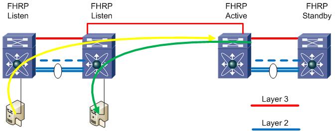
We address this with OTV by implementing filters to prevent the FHRP peers in each opposite data centers from seeing each other and therefore becoming localized.
The configuration for the IP ACL looks like this:
ip access-list HSRP_IP
10 permit udp any 224.0.0.2/32 eq 1985
20 permit udp any 224.0.0.102/32 eq 1985
This access list matches the multicast addresses for HSRPv1, and HSRPv2, though can be modified for VRRP and GLBP.
This access-list is then applied as a VACL to filter the FHRP hellos from entering the OTV through the internal interfaces. The VACL looks like below where we’ll filter HSRP on VLAN 31-33.
vlan access-map HSRP_Local 10
match ip address HSRP_IP
action drop
vlan access-map HSRP_Local 20
match ip address ALL
action forward
vlan filter HSRP_Local vlan-list 16,23
One last step we need is to create a MAC ACL to specifically filter the FHRP MAC addresses as being advertised as reachable via OTV.
The configuration for the ACL looks like this:
mac-list OTV_HSRP_VMAC_deny seq 10 deny 0000.0c07.ac00 ffff.ffff.ff00
mac-list OTV_HSRP_VMAC_deny seq 11 deny 0000.0c9f.f000 ffff.ffff.f000
mac-list OTV_HSRP_VMAC_deny seq 20 permit 0000.0000.0000 0000.0000.0000
Then we refer to the mac-list in a route-map as below:
route-map OTV_HSRP_filter permit 10
match mac-list OTV_HSRP_VMAC_deny
The final step is to add the route-map to the OTV process with the following commands.
otv-isis default
vpn Overlay0
redistribute filter route-map OTV_HSRP_filter
With these components configured we can begin to stretch VLANs between the OTV devices. This is useful for data center migrations, workload mobility or any other applications that requires layer-2 connectivity without the risks traditionally considered with LAN extension.
Related Information
Troubleshooting ARP issues across OTV
NX-OS and Cisco Nexus Switching: Next-Generation Data Center Architectures
By: Kevin Corbin, Ron Fuller, David Jansen.
ISBN-10: 1-58705-892-8
ISBN-13: 978-1-58705-892-9
Published: June 10, 2010
US SRP: $55.80
Published by Cisco Press.
- Mark as Read
- Mark as New
- Bookmark
- Permalink
- Report Inappropriate Content
Two minor corrections for this document:
1) I assume this line was meant to be for VLANs 16 and 23:
The VACL looks like below where we’ll filter HSRP on VLAN 31-33.
2) In the final step I think the "vpn Overlay0" output should be indented under the "otv-isis default" configuration. Currently it's not clear that the "vpn Overlay0" is a subconfiguration under the "otv-isis default":
otv-isis default
vpn Overlay0
redistribute filter route-map OTV_HSRP_filter
- Mark as Read
- Mark as New
- Bookmark
- Permalink
- Report Inappropriate Content
Question to the author(s):
If using GLBP instead of HSRP as our NHRP, do we need VACLs/Filters? GLBP, as I understand it, already works in a dual-active mode, so why would we need filters to keep both gateways up? Are there any other caveats with using GLBP for a stretched VLAN?
Great document. Thanks!
Justin
- Mark as Read
- Mark as New
- Bookmark
- Permalink
- Report Inappropriate Content
Justin,
GLBP will face the same sub-optimal routing issues as VRRP and HSRP. Recall that GLBP load balances by assigning different virtual MAC addresses to each AVF (active virtual forwarder) and then having the AVG (actual virtual gateway) respond to ARP requests with alternating virtual MAC addresses of the AVFs. If the GLBP traffic is not isolated, AVFs can be located over OTV, and when the AVG responds to an ARP request with their virtual MAC, traffic will be sent over OTV to be routed, which is a sub-optimal design.
Also note that the above MAC filters and route-maps are for HSRP versions 1 and 2. GLBP MAC ACLs will need to filter out the following MAC range: 0007.b400.xxxx You will also need to change the route-map filter to filter out GLBP hellos which use 224.0.0.102 UDP 3222 (HSRP uses UDP port 1985).
Austin
- Mark as Read
- Mark as New
- Bookmark
- Permalink
- Report Inappropriate Content
Austin,
This makes perfect sense. Thanks for your excellent explanation.
Justin
- Mark as Read
- Mark as New
- Bookmark
- Permalink
- Report Inappropriate Content
Do we required separate VDC for OTV configuration, or I can use same production VDC?
- Mark as Read
- Mark as New
- Bookmark
- Permalink
- Report Inappropriate Content
Hi Ron,
Bit confusing : Is IGMP involved if OTV configured with unicast mode ?
If so what can we check for IGMP command to verify control plane converged between two DCI / OTV site like sho ip mrou for multicast OTV .
OR anything else ?
I appreciate your helps.
Many Thanks,
Find answers to your questions by entering keywords or phrases in the Search bar above. New here? Use these resources to familiarize yourself with the community: