- Cisco Community
- Technology and Support
- Networking
- Networking Knowledge Base
- dual internet links NATing with PBR and IP SLA
- Subscribe to RSS Feed
- Mark as New
- Mark as Read
- Bookmark
- Subscribe
- Printer Friendly Page
- Report Inappropriate Content
- Subscribe to RSS Feed
- Mark as New
- Mark as Read
- Bookmark
- Subscribe
- Printer Friendly Page
- Report Inappropriate Content
12-18-2009 11:26 PM - edited 03-01-2019 04:28 PM
Introduction
Network Address Translation is a very common feature used to address some issues and also to meet some networks' requirements such as, overlapped networks and Internet links.
In this small document we will discuss a business requirement example, and the main idea behind this example is to demonstrate how to implement and configure NATign with dual homed Internet edge Router in conjunction with other Cisco IOS advanced features (Policy Based routing PBR and IPSLA ).
Also we will see how all of the above mentioned features work together and how IP SLA will work like a gear to this implementation in term of controlling the exit path of the traffic by controlling the default route in the routing table and PBR decision.
Requirements:
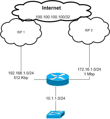
Company XYZ.com has bought a second Internet connection with 1 Mbps in addition to the existing one with 512 Kbps.
the requirement is to load share the traffic over those two links
web traffic and telnet traffic must use the the new ISP link ISP2 and all other traffic must go thorough the old ISP link ISP1
in the case of any of the above links gose down all the traffic should use the remaining link
Note:
this example has been configured in a lab environment and al the private ip addresses used in this document just for the purpose of this example
Proposed solution:
According to the above requirements we will use Policy Based routing feature to control LAN traffic going to the Internet and which path to use.
all traffic from the LAN subnet 10.1.1.0/24 destined to tcp 23, 80 and 443 must be routed to ISP 2 link with next hop 172.16.1.2
all other traffic will go though ISP 2 with next hop of 192.168.1.2
as we do not have any subnet or ip ranges to use it over the Internet we have to use NATing with overload option to use the Internet interface IP address
of each ISP link
for example traffic going through ISP 1 will be seen by ISP one and the Internet as it is from 192.168.1.1
if it is through ISP 2 will be seen as it is from 172.16.1.1
In the case of one of the links go down we need all the traffic to use the other remaining link
this will be archived here by using IP SLA with ICMP echo that will be sent to each of the ISP next hop IP addresses in our example 192.168.1.2 and 172.16.1.2
the ICMP echo will be sent every 1 second with time out of 500 msec
if the icmp reply not heard from any of those next hops within 1 second that link will be considered down and the default route in the Internet router pointing to that hop will be withdrawn from the routing table
and the PBR descion will be changed based on that as well
Configurations:
interface FastEthernet1/0
description LAN interface
ip address 10.1.1.1 255.255.255.0
ip nat inside
ip policy route-map PBR ---- this is for policy based routing
interface FastEthernet1/1
description To ISP 1
ip address 192.168.1.1 255.255.255.0
ip nat outside
!
interface FastEthernet2/0
description To ISP 2
ip address 172.16.1.1 255.255.255.0
ip nat outside
as we can see above the inside interface was configured as inside NAT interface also a policy based routing with a name of PBR applied to that interface, the configurations of this PBR will be described later
both of the Internet ISP links configured as outside NAT interfaces
IP SLA configurations:
ip sla 1
icmp-echo 192.168.1.2
timeout 500
frequency 1
ip sla schedule 1 life forever start-time now
ip sla 2
icmp-echo 172.16.1.2
timeout 500
frequency 1
ip sla schedule 2 life forever start-time now
as we can IP sla 1 will sends icp echo to ISP 1 ip address every 1 second and IP sla 2 will send it to ISP 2
track 10 rtr 1 reachability
delay down 1 up 1
!
track 20 rtr 2 reachability
delay down 1 up 1
!
if ip sla 1 did not get icmp replay within 1 second track 10 will be considered as down ( from ISP 1)
track 20 same for ISP 2
ip route 0.0.0.0 0.0.0.0 192.168.1.2 track 10
ip route 0.0.0.0 0.0.0.0 172.16.1.2 track 20
we have two default routes each one point to one of the ISP's IP address, also each static default route is associated with the corresponding IP SLA track created above
in this case if ISP 1 link is down the first default route will disappear from the routing table ( we will see this through some verifications command later in his document).
access-list 10 permit 10.1.1.0 0.0.0.255
access-list 100 permit tcp 10.1.1.0 0.0.0.255 any eq telnet
access-list 100 permit tcp 10.1.1.0 0.0.0.255 any eq www
access-list 100 permit tcp 10.1.1.0 0.0.0.255 any eq 443
access-list 101 permit ip any any
these ACLs will be used with PBR and NATing
route-map PBR permit 10
match ip address 100
set ip next-hop verify-availability 172.16.1.2 1 track 20
!
route-map PBR permit 30
match ip address 101
set ip next-hop verify-availability 192.168.1.2 2 track 10
!
we can see from the above route-map called PBR that we have several checks to our traffic coming from the LAN interface towards the Internet
first check is the ACL level
if the traffic soured from our LAN subnet 10.1.1.0/24 and going to any destination using tcp 23, 80 or 443 then this traffic will be match with ACL 100
if any thing else then will be match with ACL 101
In case of telnet traffic tcp 23, this will be match by ACL 100 and route-map sequence 10
but in this sequence we have another check before we send the traffic to the next hope 172.16.1.2, we need to make sure this next hope is up and reachable this is done by the IP SLA /track 20 created above if this track is up then the traffic will be route thorough ISP2 with a next hop 172.16.1.2
if this track 20 is down then the default static route entry points to ISP2 will be withdrawn from the routing table and traffic matched by ACL 100 under the sequence number of 10 of the route-map will be routed according to the normal routing table which is through ISP1 ( because at this stage we have only one default static route left points to ISP1). Any other traffic has not matched by ACL 100 will use the route map sequence 30 with the same concept described above
Now we can see how IP SLA controlling the routing table and the PBR choice !!!
route-map ISP2 permit 10
match ip address 10
match interface FastEthernet2/0
!
route-map ISP1 permit 10
match ip address 10
match interface FastEthernet1/1
those two Route maps will be used by the NAT command
Please note that we have in each of the route-maps match interface this interface representing the exit interface of that nat
this command is important if we do not use it the router always will use the first nating statement and all our traffic will be sourced in our example from 192.168.1.1 !!
we will see that later in this document the effect of removing the match interface from the route-map
ip nat inside source route-map ISP1 interface FastEthernet1/1 overload
ip nat inside source route-map ISP2 interface FastEthernet2/0 overload
this is simply our nating commands each with is corresponding interface and route-map
verifications:
for the verifications purposes we will use a loopback interface created on both ISP routers in our example to represent an destination in the Internet
which is 100100.100.100/32
show ip route 0.0.0.0
Routing entry for 0.0.0.0/0, supernet
Known via "static", distance 1, metric 0, candidate default path
Routing Descriptor Blocks:
192.168.1.2
Route metric is 0, traffic share count is 1
* 172.16.1.2
Route metric is 0, traffic share count is 1
we have two default route in our routing table which means both ISP routers IP addresses are reachable by SLA icmp echo
show route-map PBR
route-map PBR, permit, sequence 10
Match clauses:
ip address (access-lists): 100
Set clauses:
ip next-hop verify-availability 172.16.1.2 1 track 20 [up]
Policy routing matches: 24 packets, 1446 bytes
route-map PBR, permit, sequence 30
Match clauses:
ip address (access-lists): 101
Set clauses:
ip next-hop verify-availability 192.168.1.2 2 track 10 [up]
Policy routing matches: 60 packets, 6840 bytes
both SLA traks 10 and 20 in UP state shown in the route maps show command
now lets ping 100.100.100.100 from the an internal host in subnet 10.1.1.0/24 and we enable debug of NATing on the Internet edge router to see the translated traffic
ping 100.100.100.100
*Dec 19 20:24:44.103: NAT*: s=10.1.1.10->192.168.1.1, d=100.100.100.100 [80]
*Dec 19 20:24:44.371: NAT*: s=100.100.100.100, d=192.168.1.1->10.1.1.10 [80]
this is showing us that icmp traffic translated to ->192.168.1.1,
this means that icmp traffic has been match with ACL 101 and because track 10 is up traffic sent to 192.168.1.1 then translated using NAT
this is the PBR debug result for the above ping
*Dec 19 20:25:12.247: IP: s=10.1.1.10 (FastEthernet1/0), d=100.100.100.100, len
100, FIB policy match
*Dec 19 20:25:12.251: IP: s=10.1.1.10 (FastEthernet1/0), d=100.100.100.100, g=19
2.168.1.2, len 100, FIB policy routed
*Dec 19 20:25:12.259: NAT*: s=10.1.1.10->192.168.1.1, d=100.100.100.100 [81]
*Dec 19 20:25:12.623: NAT*: s=100.100.100.100, d=192.168.1.1->10.1.1.10 [81]
Now lets see the result when we do a telnet session from the internal network:
telnet 100.100.100.100
*Dec 19 20:26:00.375: IP: s=10.1.1.10 (FastEthernet1/0), d=100.100.100.100, len
44, FIB policy match
*Dec 19 20:26:00.375: IP: s=10.1.1.10 (FastEthernet1/0), d=100.100.100.100, g=17
2.16.1.2, len 44, FIB policy routed
*Dec 19 20:26:00.383: NAT*: s=10.1.1.10->172.16.1.1, d=100.100.100.100 [57504] --- the traffic used 172.16.1.1 link -----
*Dec 19 20:26:01.159: NAT*: s=100.100.100.100, d=172.16.1.1->10.1.1.10 [25782]
lets shut down ISP1 link to simulated a link down and see how IP SLA will work in this situation:
ping 100.100.100.100
*Dec 19 20:27:54.139: %TRACKING-5-STATE: 10 rtr 1 reachability Up->Down
*Dec 19 20:27:57.895: NAT*: s=10.1.1.10->172.16.1.1, d=100.100.100.100 [82]
*Dec 19 20:27:58.099: NAT*: s=100.100.100.100, d=172.16.1.1->10.1.1.10 [82]
now our ICMP traffic match by ACL 101 is using the link of ISP2 with 172.16.1.1 as the source IP.
we can see bellow that interface connected to ISP 1 is still up, but because the next hop not reachable via ICMP, IP SLA removed the default route that uses ISP1 next hop from the routing table
interfaces up/up but default route to ISP1 disappeared because of SAL track 10
FastEthernet1/0 10.1.1.1 YES NVRAM up up
FastEthernet1/1 192.168.1.1 YES NVRAM up up
FastEthernet2/0 172.16.1.1 YES manual up up
show ip route 0.0.0.0
Routing entry for 0.0.0.0/0, supernet
Known via "static", distance 1, metric 0, candidate default path
Routing Descriptor Blocks:
* 172.16.1.2
Route metric is 0, traffic share count is 1
lets bring it back to up now
*Dec 19 20:31:29.143: %TRACKING-5-STATE: 10 rtr 1 reachability Down->Up
Routing entry for 0.0.0.0/0, supernet
Known via "static", distance 1, metric 0, candidate default path
Routing Descriptor Blocks:
* 192.168.1.2
Route metric is 0, traffic share count is 1
172.16.1.2
Route metric is 0, traffic share count is 1
ping 100.100.100.100
*Dec 19 20:32:15.559: NAT*: s=10.1.1.10->192.168.1.1, d=100.100.100.100 [183]
*Dec 19 20:32:16.071: NAT*: s=100.100.100.100, d=192.168.1.1->10.1.1.10 [183]
Now lets remove the match interface command from each of the NAT route-maps and see the result
(config)#route-map ISP1
(config-route-map)#no ma
(config-route-map)#no match in
(config-route-map)#no match interface fa1/1
(config-route-map)#route-map ISP2
(config-route-map)#no ma
(config-route-map)#no match int fa2/0
(config-route-map)#
#clear ip nat translation *
then we do ping and telnet we will see al the traffic will be translated to 192.168.1.1 regardless which exit the traffic is using !!!
ping 100.100.100.100
*Dec 19 20:33:47.615: NAT*: s=10.1.1.10->192.168.1.1, d=100.100.100.100 [184]
*Dec 19 20:33:48.067: NAT*: s=100.100.100.100, d=192.168.1.1->10.1.1.10 [184]
*Dec 19 20:34:51.675: NAT*: i: tcp (10.1.1.10, 21603) -> (100.100.100.100, 23) [
64704]
*Dec 19 20:34:51.679: NAT*: i: tcp (10.1.1.10, 21603) -> (100.100.100.100, 23) [
64704]
*Dec 19 20:34:51.683: NAT*: s=10.1.1.10->192.168.1.1, d=100.100.100.100 [64704]
*Dec 19 20:34:51.847: NAT*: o: tcp (100.100.100.100, 23) -> (192.168.1.1, 21603)
[52374]
*Dec 19 20:34:51.847: NAT*: s=100.100.100.100, d=192.168.1.1->10.1.1.10 [52374]
*Dec 19 20:34:52.123: NAT*: i: tcp (10.1.1.10, 21603) -> (100.100.100.100, 23) [
64705]
lets put match interface back to the nat route-maps
*Dec 19 20:36:23.379: NAT*: i: icmp (10.1.1.10, 16) -> (100.100.100.100, 16) [18
5]
*Dec 19 20:36:23.383: NAT*: i: icmp (10.1.1.10, 16) -> (100.100.100.100, 16) [18
5]
*Dec 19 20:36:23.387: NAT*: s=10.1.1.10->192.168.1.1, d=100.100.100.100 [185]
*Dec 19 20:36:23.827: NAT*: o: icmp (100.100.100.100, 16) -> (192.168.1.1, 16) [
185]
*Dec 19 20:36:23.827: NAT*: s=100.100.100.100, d=192.168.1.1->10.1.1.10 [185]
telnet 100.100.100.100
*Dec 19 20:36:52.099: NAT*: i: tcp (10.1.1.10, 16305) -> (100.100.100.100, 23) [
46655]
*Dec 19 20:36:52.099: NAT*: i: tcp (10.1.1.10, 16305) -> (100.100.100.100, 23) [
46655]
*Dec 19 20:36:52.103: NAT*: s=10.1.1.10->172.16.1.1, d=100.100.100.100 [46655]
*Dec 19 20:36:52.259: NAT*: o: tcp (100.100.100.100, 23) -> (172.16.1.1, 16305)
[41145]
*Dec 19 20:36:52.259: NAT*: s=100.100.100.100, d=172.16.1.1->10.1.1.10 [41145]
*Dec 19 20:36:52.355: NAT*: i: tcp (10.1.1.10, 16305) -> (100.100.100.100, 23) [
46656]
*Dec 19 20:36:52.359: NAT*: s=10.1.1.10->172.16.1.1, d=100.100.100.100 [46656]
*Dec 19 20:36:52.375: NAT*: i: tcp (10.1.1.10, 16305) -> (100.100.100.100, 23) [
46657]
Conclusion:
to conclude the above configuration example, by using NAT with other Cisco IOS features in particular IP SLA the network will be more automated and reliable, we can track the next hop reachability and we may use other advanced features of IP sla such as link jitter, in the case that we have VOIP traffic. Also by using PBR functionalities we were able to classify our traffic and send it based on the requirements over the two links to avoid congesting one link and leave the other link as passive/back up only.
Thank you
Marwan Alshawi
- Mark as Read
- Mark as New
- Bookmark
- Permalink
- Report Inappropriate Content
Cisco has a new feature called ITD which is much superior than PBR.
It has much better load balancing capabilities than ECMP.
Please see ITD (Intelligent Traffic Director) White Paper.
Also, recent blog : Intelligent Traffic Director @ Cisco Live Milan
ITD Provides CAPEX and OPEX Savings for Customers
ITD (Intelligent Traffic Director) is a hardware based multi-Tbps Layer 4 load-balancing, traffic steering and clustering solution on Nexus 5K/6K/7K series of switches. It supports IP-stickiness, resiliency, NAT, (EFT), VIP, health monitoring, sophisticated failure handling policies, N+M redundancy, IPv4, IPv6, VRF, weighted load-balancing, bi-directional flow-coherency, and IPSLA probes including DNS.
ITD is much superior than legacy solutions like PBR, WCCP, ECMP, port-channel, layer-4 load-balancer appliances.
- Mark as Read
- Mark as New
- Bookmark
- Permalink
- Report Inappropriate Content
Hi Marwan,
Great post btw.
I have a question, since you example is on Cisco IOS router. How if this features implemented on Cisco ASA Firewall. ASA Firewall with firmware 9.4 is able to do PBR and SLA. Can ASA Firewall perform NAT with route-map as your example above.
Anyone who have experience with ASA could share, or maybe you have other solution.
Thanks!
- Mark as Read
- Mark as New
- Bookmark
- Permalink
- Report Inappropriate Content
Hello Marwan,
i know this is old thread, but i followed your document to configure the fail over and load balance on 3750 switch. i have skipped the NATing part because 3750 does not support NAT.
what happening is that:
- i can ping google or yahoo or any website from the switch but internet is not working on any of the workstation
- i am not able to ping 192.168.1.1 or 192.168.2.1, the traffic is not going out of the switch.
- i can ping 192.168.2.20 or 192.168.1.20 the IP addresses assinged on the ports of switch.
please see below the configuration:
!
!
!
spanning-tree mode pvst
spanning-tree extend system-id
!
vlan internal allocation policy ascending
!
!
!
!
interface GigabitEthernet1/0/1
!
interface GigabitEthernet1/0/2
description LAN interface
no switchport
ip address 192.168.4.1 255.255.255.0
!
interface GigabitEthernet1/0/3
!
interface GigabitEthernet1/0/4
!
interface GigabitEthernet1/0/5
!
interface GigabitEthernet1/0/6
!
interface GigabitEthernet1/0/7
!
interface GigabitEthernet1/0/8
!
interface GigabitEthernet1/0/9
!
interface GigabitEthernet1/0/10
!
interface GigabitEthernet1/0/11
!
interface GigabitEthernet1/0/12
!
interface GigabitEthernet1/0/13
!
interface GigabitEthernet1/0/14
!
interface GigabitEthernet1/0/15
!
interface GigabitEthernet1/0/16
!
interface GigabitEthernet1/0/17
!
interface GigabitEthernet1/0/18
!
interface GigabitEthernet1/0/19
!
interface GigabitEthernet1/0/20
!
interface GigabitEthernet1/0/21
!
interface GigabitEthernet1/0/22
!
interface GigabitEthernet1/0/23
no switchport
ip address 192.168.1.20 255.255.255.0
!
interface GigabitEthernet1/0/24
no switchport
ip address 192.168.2.20 255.255.255.0
!
interface GigabitEthernet1/0/25
!
interface GigabitEthernet1/0/26
!
interface GigabitEthernet1/0/27
!
interface GigabitEthernet1/0/28
!
interface Vlan1
ip address dhcp
shutdown
!
ip classless
ip route 0.0.0.0 0.0.0.0 192.168.2.1 track 10
ip route 0.0.0.0 0.0.0.0 192.168.1.1 track 20
ip http server
ip http secure-server
!
!
ip sla 1
icmp-echo 192.168.2.1
timeout 500
frequency 1
ip sla schedule 1 life forever start-time now
ip sla 2
icmp-echo 192.168.1.1
timeout 500
frequency 1
ip sla schedule 2 life forever start-time now
access-list 10 permit 192.168.4.0 0.0.0.255
access-list 100 permit tcp 192.168.4.0 0.0.0.255 any eq telnet
access-list 100 permit tcp 192.168.4.0 0.0.0.255 any eq www
access-list 100 permit tcp 192.168.4.0 0.0.0.255 any eq 443
access-list 101 permit ip any any
route-map PBR permit 10
match ip address 100
set ip next-hop verify-availability 192.168.2.1 1 track 10
!
route-map PBR permit 30
match ip address 101
set ip next-hop verify-availability 192.168.1.1 2 track 20
!
!
!
!
line con 0
line vty 0 4
login
line vty 5 15
login
!
end
Switch#
please have a look at it and tell me what am i doing wrong.
Thanks.
- Mark as Read
- Mark as New
- Bookmark
- Permalink
- Report Inappropriate Content
Hello Everyone, I need help! Please!
Here's the whole config. Whenever I shutdown the BACKUP ISP, why does the ping in my PC to 8.8.8.8 become Request Timed Out but there is internet connection when I open the browser. Another problem is that when I switch from Primary ISP to Backup ISP theres Time out also on my Ping on the PC. Is there a problem with the routing or nat? Please Help me. Thanks
=============================================================
Building configuration...
Current configuration : 5193 bytes
!
! Last configuration change at 12:31:43 GMT Mon Jul 4 2016 by altec
!
version 15.4
service timestamps debug datetime msec
service timestamps log datetime msec
service password-encryption
!
hostname PHABSRO01
!
boot-start-marker
boot-end-marker
!
!
no logging console
enable secret 5 $1$dehv$Lb1eyKFdDdhfF0gOFObu
!
aaa new-model
!
!
aaa authentication login default local
aaa authorization exec default local
!
!
!
!
!
aaa session-id common
clock timezone GMT -6 0
!
!
crypto pki trustpoint TP-self-signed-2633843759
enrollment selfsigned
subject-name cn=IOS-Self-Signed-Certificate-2633843759
revocation-check none
rsakeypair TP-self-signed-2633843759
!
!
crypto pki certificate chain TP-self-signed-2633843759
certificate self-signed 01
3082022B 30820194 A0030201 02020101 300D0609 2A864886 F70D0101 05050030
31312F30 2D060355 04031326 494F532D 53656C66 2D536967 6E65642D 43657274
69666963 6174652D 32363333 38343337 3539301E 170D3136 30343232 30303537
31375A17 0D323030 31303130 30303030 305A3031 312F302D 06035504 03132649
4F532D53 656C662D 5369676E 65642D43 65727469 66696361 74652D32 36333338
34333735 3930819F 300D0609 2A864886 F70D0101 01050003 818D0030 81890281
8100DD29 17B62779 F685E78B A6089471 7D122152 32AD50D0 6C4AD3B3 3EC921E2
99D51021 2A0009F0 11784564 9671BBF5 F0D18EC1 C608A418 3C333CF9 0CC71DC7
7EA59625 3A8BFEB4 9F93B128 3C5DB7E0 4A73E620 48A4EC81 B599069A 90FB651E
D9369884 ADF53D40 63D9FE9A 35719F95 DBF6825A 11960FCC C8FCCD1B 10ED911D
97BB0203 010001A3 53305130 0F060355 1D130101 FF040530 030101FF 301F0603
551D2304 18301680 142726ED 6349EB9E F369F177 DE95F20F 72D69356 D0301D06
03551D0E 04160414 2726ED63 49EB9EF3 69F177DE 95F20F72 D69356D0 300D0609
2A864886 F70D0101 05050003 81810064 81EDDBE3 37C81E29 A4939114 826C53DD
90D99054 2D2C6D4C C3368338 ACBCE1DA A9940078 F85253E6 0D676C01 34EC2499
D2985B58 AFACB18C 51D8A8EE 6973F81C 8E68F3EE 77D4CA52 1A105D50 3CD12500
8C07287C 69D14F48 D4374E00 DABFF889 29F39CB1 A58CD415 E35385B2 AC959A81
415F23B1 190C8B24 38EFFEF0 E43422
quit
!
!
!
!
!
!
!
!
!
!
!
!
!
ip name-server 121.58.250.195
ip cef
no ipv6 cef
!
!
multilink bundle-name authenticated
!
!
cts logging verbose
license udi pid CISCO2951/K9 sn FJC1941A0TY
!
!
username admin privilege 15 secret 5 $1$y9QH$ysAWFM.Gu.LBQ.vJkaNq
username altec privilege 15 secret 5 $1$JlZh$dNsI45Ic4NU7Z3af0Ou.
!
redundancy
!
!
!
!
!
track 10 ip sla 1 reachability
delay down 1 up 10
!
!
!
crypto isakmp policy 1
encr 3des
authentication pre-share
group 2
crypto isakmp key default address 198.105.204.212
!
!
crypto ipsec transform-set Five9 esp-3des esp-sha-hmac
mode tunnel
!
!
!
crypto map CMAP 10 ipsec-isakmp
set peer 198.105.204.212
set transform-set Five9
match address Five9-List
!
!
!
!
!
interface Embedded-Service-Engine0/0
no ip address
shutdown
!
interface GigabitEthernet0/0
description ===ConvergeWAN===
ip address 11.125.86.194 255.255.255.224
ip nat outside
ip nat enable
ip virtual-reassembly in
duplex auto
speed auto
crypto map CMAP
!
interface GigabitEthernet0/1
description <<<<<PLDTWAN>>>>>
ip address 158.71.72.174 255.255.255.252
ip nat outside
ip nat enable
ip virtual-reassembly in
duplex auto
speed auto
crypto map CMAP
!
interface GigabitEthernet0/2
description Altec LAN
ip address 10.0.10.1 255.255.254.0
ip nat inside
ip virtual-reassembly in
duplex auto
speed auto
no mop enabled
!
ip forward-protocol nd
!
ip http server
ip http authentication local
ip http secure-server
!
ip nat inside source route-map CONVERGE interface GigabitEthernet0/0 overload
ip nat inside source route-map PLDT interface GigabitEthernet0/1 overload
ip route 0.0.0.0 0.0.0.0 11.125.86.193 track 10
ip route 0.0.0.0 0.0.0.0 158.71.72.173 100
!
ip access-list extended Five9-List
permit ip 10.0.10.0 0.0.1.255 38.107.71.0 0.0.0.255
permit ip 10.0.10.0 0.0.1.255 198.105.200.0 0.0.0.255
!
ip sla 1
icmp-echo 8.8.8.8 source-interface GigabitEthernet0/0
threshold 3000
frequency 5
ip sla schedule 1 life forever start-time now
!
route-map CONVERGE permit 10
match ip address 103
match interface GigabitEthernet0/0
!
route-map PLDT permit 10
match ip address 103
match interface GigabitEthernet0/1
!
!
snmp-server community public RO
access-list 103 permit ip 10.0.10.0 0.0.1.255 any
!
!
!
control-plane
!
!
banner motd ^CC
************************************************
* WARNING: Unauthorized Access Prohibited *
* Access on this gateway are punishable by the *
, under*
* RA 1987. *
* -ALTEC *
************************************************
^C
!
line con 0
line aux 0
line 2
no activation-character
no exec
transport preferred none
transport output none
stopbits 1
line vty 0 4
password 7 015226084F5805417815
transport preferred telnet
transport input all
transport output all
!
scheduler allocate 20000 1000
event manager applet check-isp
event track 1 state any
action 1.0 cli command "enable"
action 1.5 cli command "clear ip nat trans *"
action 2.0 syslog priority notifications msg "Nat translation cleared!"
!
end
- Mark as Read
- Mark as New
- Bookmark
- Permalink
- Report Inappropriate Content
Hi Marwan,
Nice Article.
I am using Pindom to monitor my links and servers, and using given configuration i am not able to ping 2nd ISP IP Address when primary is up (as default route is towards ISP1) I am not sure if any thing wrong or this is normal behavior ?
Is there anyway to get 2nd ISP IP Address pingable ?
- Mark as Read
- Mark as New
- Bookmark
- Permalink
- Report Inappropriate Content
Hai,
One of our location we are using 2 links Primary and Secondary. Pri - 2 mbps sec -2 mbps, Pri - Data link sec - VC and data. In this location always bandwidth chock, due full utilization 2 mbps. What i am thinking is to loadbalance with PBR. Once primary link touch 70 % of utilization, remaining 30 % of utilization should switch over to secondary link.
Through this i can avoid bandwidth chock.
- Mark as Read
- Mark as New
- Bookmark
- Permalink
- Report Inappropriate Content
Hi Marwan Alshawi
Thank you for the excellent article although I must confess I'm struggling with it a bit, I get all the config in as below however while I can ping out through the device I still have no internet connection (ICMP traffic only works).
I also don't see any packets hitting the NAT_Vocus or NAT_iinet route-maps, any help is greatly appreciated, please see config below.
EDIT: We want Voip traffic to exit via Vocus and Prod traffic via iinet with a failover in both direction should a connection go down.
!
version 15.6
boot system flash c800-universalk9-mz.SPA.156-2.T2.bin
!
track 10 ip sla 10
delay down 15 up 10
!
track 101 ip sla 101
delay down 15 up 10
!
interface Vlan10
description iinet NBN Vlan
ip address dhcp
ip access-group ACL-INBOUND in
ip flow ingress
ip nat outside
ip virtual-reassembly in
ip policy route-map NAT_iinet
auto qos voip trust
!
interface Vlan20
description CHAP-Production
ip address 192.168.0.1 255.255.255.0
ip nat inside
ip virtual-reassembly in
ip policy route-map NAT_Failover
!
interface Vlan30
description CHAP-VOICE
ip address 192.168.30.1 255.255.255.0
ip nat inside
ip virtual-reassembly in
ip policy route-map NAT_Failover
!
interface Vlan101
description VOCUS BACKUP 2/2
ip address 203.161.x.x 255.255.255.252
ip nat outside
ip virtual-reassembly in
ip policy route-map NAT_Vocus
!
ip forward-protocol nd
no ip http server
no ip http secure-server
!
!
ip dns server
no ip nat service sip udp port 5060
ip nat pool CHAP_INTERENT 203.59.x.x 203.59.x.x netmask 255.255.255.252
ip nat inside source static tcp 192.168.0.1 22 interface Vlan10 22
ip nat inside source static tcp 192.168.30.1 22 interface Vlan101 22
ip nat inside source route-map NAT_Vocus pool CHAP_INTERENT overload
ip nat inside source route-map NAT_iinet interface Vlan10 overload
ip nat inside source static tcp 192.168.0.10 25 203.59.x.x 25 extendable
ip nat inside source static tcp 192.168.0.5 80 203.59.x.x 80 extendable
ip nat inside source static tcp 192.168.0.5 443 203.59.x.x 443 extendable
ip nat inside source static tcp 192.168.0.48 3389 203.59.x.x 3330 extendable
ip nat inside source static tcp 192.168.0.5 3389 203.59.x.x 3389 extendable
ip nat inside source static tcp 192.168.0.10 3390 203.59.x.x 3390 extendable
ip nat inside source static tcp 192.168.0.2 3389 203.59.x.x 3391 extendable
ip nat inside source static tcp 192.168.0.3 3389 203.59.x.x 3392 extendable
ip nat inside source static tcp 192.168.0.4 80 203.59.x.x 3393 extendable
ip nat inside source static tcp 192.168.30.11 8000 203.59.x.x 8000 extendable
ip nat inside source static tcp 192.168.30.11 80 203.59.x.x 8888 extendable
ip route 0.0.0.0 0.0.0.0 Vlan10 track 10
ip route 0.0.0.0 0.0.0.0 203.161.x.x track 101
!
ip access-list extended ACL-INBOUND
permit ip object-group Novum-IPs any
permit ip object-group NECALL-IPs any
deny tcp any any eq 8888
permit ip any any
ip access-list extended CHAP_NAT
deny ip host 192.168.0.100 any
permit ip 192.168.0.0 0.0.0.255 any
permit ip 192.168.30.0 0.0.0.255 any
ip access-list extended CHAP_NAT_PROD
deny ip host 192.168.0.100 any
permit ip 192.168.0.0 0.0.0.255 any
ip access-list extended CHAP_NAT_VOICE
permit ip 192.168.30.0 0.0.0.255 any
ip sla auto discovery
ip sla 10
icmp-echo 203.0.x.x source-interface Vlan10
threshold 40
timeout 1000
frequency 3
ip sla schedule 10 life forever start-time now
ip sla 101
icmp-echo 203.161.x.x source-interface Vlan101
threshold 40
timeout 1000
frequency 3
ip sla schedule 101 life forever start-time now
dialer-list 1 protocol ip permit
dialer-list 2 protocol ip permit
!
route-map NAT_Failover permit 10
match ip address CHAP_NAT_PROD
set ip next-hop verify-availability 203.59.x.x 10 track 10
set ip next-hop verify-availability 203.161.x.x 20 track 101
!
route-map NAT_Failover permit 20
match ip address CHAP_NAT_VOICE
set ip next-hop verify-availability 203.161.x.x 10 track 101
set ip next-hop verify-availability 203.59.x.x 20 track 10
!
route-map NAT_Vocus permit 10
match ip address CHAP_NAT
match interface Vlan101
!
route-map NAT_iinet permit 10
match ip address CHAP_NAT
match interface Vlan10
!
- Mark as Read
- Mark as New
- Bookmark
- Permalink
- Report Inappropriate Content
Hello Marwan,
Thank you so much for your article. I am kind of confused on the route statements that match the ACL 10. Could you explain further while that command is necessary? In the event where isp 1 goes down , what is the fate of other traffic as ACL 100 matches only the telnet traffic and web traffic to isp2. Is this why the ACL 10 comes in
- « Previous
- Next »
Find answers to your questions by entering keywords or phrases in the Search bar above. New here? Use these resources to familiarize yourself with the community: