- Cisco Community
- Technology and Support
- Networking
- Networking Knowledge Base
- dual internet links NATing with PBR and IP SLA
- Subscribe to RSS Feed
- Mark as New
- Mark as Read
- Bookmark
- Subscribe
- Printer Friendly Page
- Report Inappropriate Content
- Subscribe to RSS Feed
- Mark as New
- Mark as Read
- Bookmark
- Subscribe
- Printer Friendly Page
- Report Inappropriate Content
12-18-2009 11:26 PM - edited 03-01-2019 04:28 PM
Introduction
Network Address Translation is a very common feature used to address some issues and also to meet some networks' requirements such as, overlapped networks and Internet links.
In this small document we will discuss a business requirement example, and the main idea behind this example is to demonstrate how to implement and configure NATign with dual homed Internet edge Router in conjunction with other Cisco IOS advanced features (Policy Based routing PBR and IPSLA ).
Also we will see how all of the above mentioned features work together and how IP SLA will work like a gear to this implementation in term of controlling the exit path of the traffic by controlling the default route in the routing table and PBR decision.
Requirements:
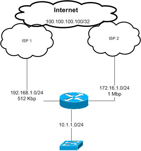
Company XYZ.com has bought a second Internet connection with 1 Mbps in addition to the existing one with 512 Kbps.
the requirement is to load share the traffic over those two links
web traffic and telnet traffic must use the the new ISP link ISP2 and all other traffic must go thorough the old ISP link ISP1
in the case of any of the above links gose down all the traffic should use the remaining link
Note:
this example has been configured in a lab environment and al the private ip addresses used in this document just for the purpose of this example
Proposed solution:
According to the above requirements we will use Policy Based routing feature to control LAN traffic going to the Internet and which path to use.
all traffic from the LAN subnet 10.1.1.0/24 destined to tcp 23, 80 and 443 must be routed to ISP 2 link with next hop 172.16.1.2
all other traffic will go though ISP 2 with next hop of 192.168.1.2
as we do not have any subnet or ip ranges to use it over the Internet we have to use NATing with overload option to use the Internet interface IP address
of each ISP link
for example traffic going through ISP 1 will be seen by ISP one and the Internet as it is from 192.168.1.1
if it is through ISP 2 will be seen as it is from 172.16.1.1
In the case of one of the links go down we need all the traffic to use the other remaining link
this will be archived here by using IP SLA with ICMP echo that will be sent to each of the ISP next hop IP addresses in our example 192.168.1.2 and 172.16.1.2
the ICMP echo will be sent every 1 second with time out of 500 msec
if the icmp reply not heard from any of those next hops within 1 second that link will be considered down and the default route in the Internet router pointing to that hop will be withdrawn from the routing table
and the PBR descion will be changed based on that as well
Configurations:
interface FastEthernet1/0
description LAN interface
ip address 10.1.1.1 255.255.255.0
ip nat inside
ip policy route-map PBR ---- this is for policy based routing
interface FastEthernet1/1
description To ISP 1
ip address 192.168.1.1 255.255.255.0
ip nat outside
!
interface FastEthernet2/0
description To ISP 2
ip address 172.16.1.1 255.255.255.0
ip nat outside
as we can see above the inside interface was configured as inside NAT interface also a policy based routing with a name of PBR applied to that interface, the configurations of this PBR will be described later
both of the Internet ISP links configured as outside NAT interfaces
IP SLA configurations:
ip sla 1
icmp-echo 192.168.1.2
timeout 500
frequency 1
ip sla schedule 1 life forever start-time now
ip sla 2
icmp-echo 172.16.1.2
timeout 500
frequency 1
ip sla schedule 2 life forever start-time now
as we can IP sla 1 will sends icp echo to ISP 1 ip address every 1 second and IP sla 2 will send it to ISP 2
track 10 rtr 1 reachability
delay down 1 up 1
!
track 20 rtr 2 reachability
delay down 1 up 1
!
if ip sla 1 did not get icmp replay within 1 second track 10 will be considered as down ( from ISP 1)
track 20 same for ISP 2
ip route 0.0.0.0 0.0.0.0 192.168.1.2 track 10
ip route 0.0.0.0 0.0.0.0 172.16.1.2 track 20
we have two default routes each one point to one of the ISP's IP address, also each static default route is associated with the corresponding IP SLA track created above
in this case if ISP 1 link is down the first default route will disappear from the routing table ( we will see this through some verifications command later in his document).
access-list 10 permit 10.1.1.0 0.0.0.255
access-list 100 permit tcp 10.1.1.0 0.0.0.255 any eq telnet
access-list 100 permit tcp 10.1.1.0 0.0.0.255 any eq www
access-list 100 permit tcp 10.1.1.0 0.0.0.255 any eq 443
access-list 101 permit ip any any
these ACLs will be used with PBR and NATing
route-map PBR permit 10
match ip address 100
set ip next-hop verify-availability 172.16.1.2 1 track 20
!
route-map PBR permit 30
match ip address 101
set ip next-hop verify-availability 192.168.1.2 2 track 10
!
we can see from the above route-map called PBR that we have several checks to our traffic coming from the LAN interface towards the Internet
first check is the ACL level
if the traffic soured from our LAN subnet 10.1.1.0/24 and going to any destination using tcp 23, 80 or 443 then this traffic will be match with ACL 100
if any thing else then will be match with ACL 101
In case of telnet traffic tcp 23, this will be match by ACL 100 and route-map sequence 10
but in this sequence we have another check before we send the traffic to the next hope 172.16.1.2, we need to make sure this next hope is up and reachable this is done by the IP SLA /track 20 created above if this track is up then the traffic will be route thorough ISP2 with a next hop 172.16.1.2
if this track 20 is down then the default static route entry points to ISP2 will be withdrawn from the routing table and traffic matched by ACL 100 under the sequence number of 10 of the route-map will be routed according to the normal routing table which is through ISP1 ( because at this stage we have only one default static route left points to ISP1). Any other traffic has not matched by ACL 100 will use the route map sequence 30 with the same concept described above
Now we can see how IP SLA controlling the routing table and the PBR choice !!!
route-map ISP2 permit 10
match ip address 10
match interface FastEthernet2/0
!
route-map ISP1 permit 10
match ip address 10
match interface FastEthernet1/1
those two Route maps will be used by the NAT command
Please note that we have in each of the route-maps match interface this interface representing the exit interface of that nat
this command is important if we do not use it the router always will use the first nating statement and all our traffic will be sourced in our example from 192.168.1.1 !!
we will see that later in this document the effect of removing the match interface from the route-map
ip nat inside source route-map ISP1 interface FastEthernet1/1 overload
ip nat inside source route-map ISP2 interface FastEthernet2/0 overload
this is simply our nating commands each with is corresponding interface and route-map
verifications:
for the verifications purposes we will use a loopback interface created on both ISP routers in our example to represent an destination in the Internet
which is 100100.100.100/32
show ip route 0.0.0.0
Routing entry for 0.0.0.0/0, supernet
Known via "static", distance 1, metric 0, candidate default path
Routing Descriptor Blocks:
192.168.1.2
Route metric is 0, traffic share count is 1
* 172.16.1.2
Route metric is 0, traffic share count is 1
we have two default route in our routing table which means both ISP routers IP addresses are reachable by SLA icmp echo
show route-map PBR
route-map PBR, permit, sequence 10
Match clauses:
ip address (access-lists): 100
Set clauses:
ip next-hop verify-availability 172.16.1.2 1 track 20 [up]
Policy routing matches: 24 packets, 1446 bytes
route-map PBR, permit, sequence 30
Match clauses:
ip address (access-lists): 101
Set clauses:
ip next-hop verify-availability 192.168.1.2 2 track 10 [up]
Policy routing matches: 60 packets, 6840 bytes
both SLA traks 10 and 20 in UP state shown in the route maps show command
now lets ping 100.100.100.100 from the an internal host in subnet 10.1.1.0/24 and we enable debug of NATing on the Internet edge router to see the translated traffic
ping 100.100.100.100
*Dec 19 20:24:44.103: NAT*: s=10.1.1.10->192.168.1.1, d=100.100.100.100 [80]
*Dec 19 20:24:44.371: NAT*: s=100.100.100.100, d=192.168.1.1->10.1.1.10 [80]
this is showing us that icmp traffic translated to ->192.168.1.1,
this means that icmp traffic has been match with ACL 101 and because track 10 is up traffic sent to 192.168.1.1 then translated using NAT
this is the PBR debug result for the above ping
*Dec 19 20:25:12.247: IP: s=10.1.1.10 (FastEthernet1/0), d=100.100.100.100, len
100, FIB policy match
*Dec 19 20:25:12.251: IP: s=10.1.1.10 (FastEthernet1/0), d=100.100.100.100, g=19
2.168.1.2, len 100, FIB policy routed
*Dec 19 20:25:12.259: NAT*: s=10.1.1.10->192.168.1.1, d=100.100.100.100 [81]
*Dec 19 20:25:12.623: NAT*: s=100.100.100.100, d=192.168.1.1->10.1.1.10 [81]
Now lets see the result when we do a telnet session from the internal network:
telnet 100.100.100.100
*Dec 19 20:26:00.375: IP: s=10.1.1.10 (FastEthernet1/0), d=100.100.100.100, len
44, FIB policy match
*Dec 19 20:26:00.375: IP: s=10.1.1.10 (FastEthernet1/0), d=100.100.100.100, g=17
2.16.1.2, len 44, FIB policy routed
*Dec 19 20:26:00.383: NAT*: s=10.1.1.10->172.16.1.1, d=100.100.100.100 [57504] --- the traffic used 172.16.1.1 link -----
*Dec 19 20:26:01.159: NAT*: s=100.100.100.100, d=172.16.1.1->10.1.1.10 [25782]
lets shut down ISP1 link to simulated a link down and see how IP SLA will work in this situation:
ping 100.100.100.100
*Dec 19 20:27:54.139: %TRACKING-5-STATE: 10 rtr 1 reachability Up->Down
*Dec 19 20:27:57.895: NAT*: s=10.1.1.10->172.16.1.1, d=100.100.100.100 [82]
*Dec 19 20:27:58.099: NAT*: s=100.100.100.100, d=172.16.1.1->10.1.1.10 [82]
now our ICMP traffic match by ACL 101 is using the link of ISP2 with 172.16.1.1 as the source IP.
we can see bellow that interface connected to ISP 1 is still up, but because the next hop not reachable via ICMP, IP SLA removed the default route that uses ISP1 next hop from the routing table
interfaces up/up but default route to ISP1 disappeared because of SAL track 10
FastEthernet1/0 10.1.1.1 YES NVRAM up up
FastEthernet1/1 192.168.1.1 YES NVRAM up up
FastEthernet2/0 172.16.1.1 YES manual up up
show ip route 0.0.0.0
Routing entry for 0.0.0.0/0, supernet
Known via "static", distance 1, metric 0, candidate default path
Routing Descriptor Blocks:
* 172.16.1.2
Route metric is 0, traffic share count is 1
lets bring it back to up now
*Dec 19 20:31:29.143: %TRACKING-5-STATE: 10 rtr 1 reachability Down->Up
Routing entry for 0.0.0.0/0, supernet
Known via "static", distance 1, metric 0, candidate default path
Routing Descriptor Blocks:
* 192.168.1.2
Route metric is 0, traffic share count is 1
172.16.1.2
Route metric is 0, traffic share count is 1
ping 100.100.100.100
*Dec 19 20:32:15.559: NAT*: s=10.1.1.10->192.168.1.1, d=100.100.100.100 [183]
*Dec 19 20:32:16.071: NAT*: s=100.100.100.100, d=192.168.1.1->10.1.1.10 [183]
Now lets remove the match interface command from each of the NAT route-maps and see the result
(config)#route-map ISP1
(config-route-map)#no ma
(config-route-map)#no match in
(config-route-map)#no match interface fa1/1
(config-route-map)#route-map ISP2
(config-route-map)#no ma
(config-route-map)#no match int fa2/0
(config-route-map)#
#clear ip nat translation *
then we do ping and telnet we will see al the traffic will be translated to 192.168.1.1 regardless which exit the traffic is using !!!
ping 100.100.100.100
*Dec 19 20:33:47.615: NAT*: s=10.1.1.10->192.168.1.1, d=100.100.100.100 [184]
*Dec 19 20:33:48.067: NAT*: s=100.100.100.100, d=192.168.1.1->10.1.1.10 [184]
*Dec 19 20:34:51.675: NAT*: i: tcp (10.1.1.10, 21603) -> (100.100.100.100, 23) [
64704]
*Dec 19 20:34:51.679: NAT*: i: tcp (10.1.1.10, 21603) -> (100.100.100.100, 23) [
64704]
*Dec 19 20:34:51.683: NAT*: s=10.1.1.10->192.168.1.1, d=100.100.100.100 [64704]
*Dec 19 20:34:51.847: NAT*: o: tcp (100.100.100.100, 23) -> (192.168.1.1, 21603)
[52374]
*Dec 19 20:34:51.847: NAT*: s=100.100.100.100, d=192.168.1.1->10.1.1.10 [52374]
*Dec 19 20:34:52.123: NAT*: i: tcp (10.1.1.10, 21603) -> (100.100.100.100, 23) [
64705]
lets put match interface back to the nat route-maps
*Dec 19 20:36:23.379: NAT*: i: icmp (10.1.1.10, 16) -> (100.100.100.100, 16) [18
5]
*Dec 19 20:36:23.383: NAT*: i: icmp (10.1.1.10, 16) -> (100.100.100.100, 16) [18
5]
*Dec 19 20:36:23.387: NAT*: s=10.1.1.10->192.168.1.1, d=100.100.100.100 [185]
*Dec 19 20:36:23.827: NAT*: o: icmp (100.100.100.100, 16) -> (192.168.1.1, 16) [
185]
*Dec 19 20:36:23.827: NAT*: s=100.100.100.100, d=192.168.1.1->10.1.1.10 [185]
telnet 100.100.100.100
*Dec 19 20:36:52.099: NAT*: i: tcp (10.1.1.10, 16305) -> (100.100.100.100, 23) [
46655]
*Dec 19 20:36:52.099: NAT*: i: tcp (10.1.1.10, 16305) -> (100.100.100.100, 23) [
46655]
*Dec 19 20:36:52.103: NAT*: s=10.1.1.10->172.16.1.1, d=100.100.100.100 [46655]
*Dec 19 20:36:52.259: NAT*: o: tcp (100.100.100.100, 23) -> (172.16.1.1, 16305)
[41145]
*Dec 19 20:36:52.259: NAT*: s=100.100.100.100, d=172.16.1.1->10.1.1.10 [41145]
*Dec 19 20:36:52.355: NAT*: i: tcp (10.1.1.10, 16305) -> (100.100.100.100, 23) [
46656]
*Dec 19 20:36:52.359: NAT*: s=10.1.1.10->172.16.1.1, d=100.100.100.100 [46656]
*Dec 19 20:36:52.375: NAT*: i: tcp (10.1.1.10, 16305) -> (100.100.100.100, 23) [
46657]
Conclusion:
to conclude the above configuration example, by using NAT with other Cisco IOS features in particular IP SLA the network will be more automated and reliable, we can track the next hop reachability and we may use other advanced features of IP sla such as link jitter, in the case that we have VOIP traffic. Also by using PBR functionalities we were able to classify our traffic and send it based on the requirements over the two links to avoid congesting one link and leave the other link as passive/back up only.
Thank you
Marwan Alshawi
- Mark as Read
- Mark as New
- Bookmark
- Permalink
- Report Inappropriate Content
Hi Marwanshawi,
Sorry to disturb you. Just wanted to get some inputs from you regarding on this.
ip sla monitor 1
type echo protocol ipIcmpEcho x.x.x.x =next hop ip
timeout 50
frequency 3
ip sla monitor schedule 1 life forever start-time now
track 1 rtr 1 reachability
interface FastEthernet0/1
ip address 150.200.19.251 255.255.255.0
ip nat inside
ip virtual-reassembly
duplex auto
speed auto
standby 1 ip 150.200.19.254
standby 1 preempt
standby 1 track 1
ip route 0.0.0.0 0.0.0.0 ISP1 track 1
This configs works fine only if the target host is the next hop ip.
But when i change it to any other public ip like 4.2.2.2, HSRP state change to standby
Any idea on this? I was trying to make some work arounds on this but still it doesnt work.
- Mark as Read
- Mark as New
- Bookmark
- Permalink
- Report Inappropriate Content
in your default route route you don't need the track command as the LAN using HSRP and when track 10is down router 2 already will be come the active router, other config looks ok
however you mentioned about the SLA icmp works only to a next hop ip !! this looks like reachability issue
not sure but check that the source IP is reachable i think you are using nating maybe you need to use a reachable IP
good luck
- Mark as Read
- Mark as New
- Bookmark
- Permalink
- Report Inappropriate Content
Yes im using Nating.
when i do testing using extending ping with source address or even if just a simple ping, 4.2.2.2 is reachable.
I was bit confused on this.
I also use" type echo protocol ipIcmpEcho 4.2.2.2 source-ipaddr 121.96.179.1 and source interface"
still hsrp goes standby.. only next hop ip works ok..
Sorry to bother you on this.
- Mark as Read
- Mark as New
- Bookmark
- Permalink
- Report Inappropriate Content
Hi Marwanshawi,
Case resolved
type echo protocol ipIcmpEcho 4.2.2.2
timeout 50 (change to 10000)
I just change the value for timeout to 10000 already works fine since I've found out that reachability to 4.2.2.2 is more than 50.
Also i used MHSRP to load share the traffic..
Thanks
- Mark as Read
- Mark as New
- Bookmark
- Permalink
- Report Inappropriate Content
Marwanshawi,
Is it possible to use your config and monitor primary line for failover to secondary line? Then return to pri when line is back up? I have two ethernet WAN's. I thought I would add a metric of 254 for second route and not use a second sla.
Will this work?
- Mark as Read
- Mark as New
- Bookmark
- Permalink
- Report Inappropriate Content
with IP SLA yes, and you can monitorfor example the primary interface line protocol, once its down the track for the primary interface wll be down and the secondary will take over
- Mark as Read
- Mark as New
- Bookmark
- Permalink
- Report Inappropriate Content
But once primary is online again will primary route be 1st again?
Should I add sla 2 and track 2 as in your example?
Thanks,
Bob
- Mark as Read
- Mark as New
- Bookmark
- Permalink
- Report Inappropriate Content
Definitely primary route goes active again once primary link is up and traffic should be passing on it considering you properly configured tracking.
- Mark as Read
- Mark as New
- Bookmark
- Permalink
- Report Inappropriate Content
ok, got it working except for one problem. I also have a point to point vpn between my routers. Once I add the second route, I start to see dropped packets to my remote vpn subnets and communication between subnets stop. Also notice that default route changes on its own, and becomes the secondary route even while the primary is still up and running Any ideas? Thanks
- Mark as Read
- Mark as New
- Bookmark
- Permalink
- Report Inappropriate Content
Thanks I Appriciate your efforts in sharing such a great solution.
I have to implement a scenario, where a customer has existing internet link from 1 ISP. Now they have another ADSL link and they would like to utilize it for all the internet traffic (www, http etc). So they want to utilize 1st ISP link only for there emails.
I am looking for an optimal solution to do the load sharing (traffic policing). At the moment we are using, IP NATing. so the ISP facing interface we have ip nat outside and ip nat inside on the inside interface and using "ip nat inside source static 172.16.6.4 212.93.201.183 extendable" on the global.
your feedback on this would be highly appreciated.
- Mark as Read
- Mark as New
- Bookmark
- Permalink
- Report Inappropriate Content
HI there
from what you've described above PBR will be the optiyou can use
however i am not sure how much is the load on your router becuase if the router and traffic will be very busy this will make increase on the Router CPU wiht PBR and NATing thats why you need to watch this
in the above example you can see you can use ACL wit route maps to policy route the traffic PBR ( simple)
for nating make sure you follow the above example config as you will have one inside nat and two outside enating
you need to use the method used with route maps to get your nating working with both ISPs links
IPSLA i would it is optional up to you if you want to monitor the links and do failover as if one of the links gose down without IPSLA configured like above thePBR will blackhole your traffic and keep send it
good luck
- Mark as Read
- Mark as New
- Bookmark
- Permalink
- Report Inappropriate Content
Thanks Marwan,
I wanted to inquire about another scenario, where we have two links from same ISP. First one was a temprory link, when ISP provided temprory IP Addresses for some servers (web, mail etc).
What is the best way to do the load sharing between both. As per my understanding, i will again do IP NAT outside on both the ISP interfaces. plus we will have two default routes, because we have two point-to-point links between the same ISP.
any suggestions would be appreciated.
thanks
- Mark as Read
- Mark as New
- Bookmark
- Permalink
- Report Inappropriate Content
even if you have the two links from the same ISP the idea still the same
the two default routes are must to have both liks forwarding traffic to your ISP
use the nating method above as you will have diffrent public ip on each link from your ISP
if you looking to do loadsharing based on traffic type like http smtp ..etc this can be done using PBR
if you just want loading the traffic on both links your two static routes will do load balancing
however the loadbalncing will be according tp CEF the default is per session ( not very even loadbalncing)
you can change it in the interface level to be per packet but this has several disadvantages such as high CPU and out of order TCP
hope this help
- Mark as Read
- Mark as New
- Bookmark
- Permalink
- Report Inappropriate Content
Thanks again Marwan for your feedback. I appreciate it.
- Mark as Read
- Mark as New
- Bookmark
- Permalink
- Report Inappropriate Content
hi Marwan,
Thanks for your great articile. i would like to post a question regarding such setup. let say i have a web server using TCP port 8080 for external access, is it possible to have 2 static NATs for both ISP link to a single inside host? will it cause any issue?
Example:
Inside host:
192.168.1.100 tcp port 8080
NAT
1. static nat 10.10.10.10 (ISP1) tcp 8080 to 192.168.1.100 tcp port 8080
2. static nat 20.20.20.20 (ISP2) tcp 8080 to 192.168.1.100 tcp port 8080
my intention is my remote user can choose their own prefer path to access from internet since the router will not be able to control inbound traffic. if the user feel that isp1 is slow, they can manual switch to isp2.
hope that you can help me. thanks.
Find answers to your questions by entering keywords or phrases in the Search bar above. New here? Use these resources to familiarize yourself with the community: