- Cisco Community
- Technology and Support
- Networking
- Networking Knowledge Base
- ELAM Example: Nexus7000 M-Series
- Subscribe to RSS Feed
- Mark as New
- Mark as Read
- Bookmark
- Subscribe
- Printer Friendly Page
- Report Inappropriate Content
- Subscribe to RSS Feed
- Mark as New
- Mark as Read
- Bookmark
- Subscribe
- Printer Friendly Page
- Report Inappropriate Content
09-07-2013 06:55 PM - edited 03-01-2019 04:57 PM
This document provides the steps to perform an ELAM on the Nexus 7000 M-Series modules, explains the most relevant outputs, and how to interpret their results. Please refer to the following document for an overview on ELAM:
Topology
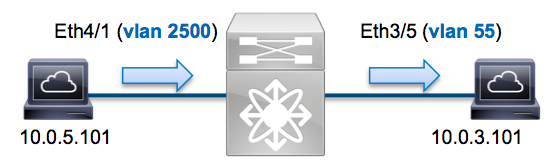
In this example a host on Vlan2500 (10.0.5.101) port Eth4/1 sends an ICMP request to a host on Vlan55 (10.0.3.101) off port Eth3/5. We will use ELAM to capture this single packet from 10.0.5.101 to 10.0.3.101. It's important to remember that ELAM allows us to capture a single frame.
To perform an ELAM on the Nexus7000, you need to first attach to the appropriate module. This requires the network-admin privilege.
N7K# attach module 4
Attaching to module 4 ...
To exit type 'exit', to abort type '$.'
module-4#
Determine the ingress FE
We expect the traffic to ingress the switch on port Eth4/1. Checking the modules in the system we can see that module 4 is an M-series module. Remember, the Nexus 7000 is fully distributed and the modules, not the supervisor, are responsible for making the forwarding decision for dataplane traffic.
N7K# show module
Mod Ports Module-Type Model Status
--- ----- ----------------------------------- ------------------ ----------
3 32 10 Gbps Ethernet Module N7K-M132XP-12 ok
4 48 10/100/1000 Mbps Ethernet Module N7K-M148GT-11 ok
5 0 Supervisor module-1X N7K-SUP1 active *
6 0 Supervisor module-1X N7K-SUP1 ha-standby
For M-Series modules, we want to perform the ELAM on the L2 forwarding engine (FE) with internal codename Eureka. Note that the L2 FE data bus (DBUS) contains original header information before the L2 and L3 lookup and the result bus (RBUS) contains the results after both L3 and L2 lookups.
Nexus 7000 modules can have multiple FEs per module. We need to determine which Eureka ASIC is the FE for port Eth4/1. We can use the following command to verify:
module-4# show hardware internal dev-port-map
(some output omitted)
--------------------------------------------------------------
CARD_TYPE: 48 port 1G
>Front Panel ports:48
--------------------------------------------------------------
Device name Dev role Abbr num_inst:
--------------------------------------------------------------
> Eureka DEV_LAYER_2_LOOKUP L2LKP 1
+--------------------------------------------------------------+
+-----------+++FRONT PANEL PORT TO ASIC INSTANCE MAP+++--------+
+--------------------------------------------------------------+
FP port|PHYS |SECUR |MAC_0 |RWR_0 |L2LKP |L3LKP |QUEUE |SWICHF
1 0 0 0 0 0 0 0 0
2 0 0 0 0 0 0 0 0
From the output above, we can see that Eth4/1 is on Eureka (L2LKP) instance 0. Note for M-Series modules, the ELAM syntax utilizes 1-based values so instance 0 becomes instance 1 when setting up the ELAM. This is not the case for F-Series modules.
module-4# elam asic eureka instance 1
module-4(eureka-elam)#
Configure the Trigger
The Eureka ASIC supports ELAM triggers for IPv4, IPv6, and Other. The ELAM trigger must align to the frame type. If the frame is an IPv4 frame then the trigger must also be IPv4. An IPv4 frame will not be captured with an "other" trigger. The same logic applies to IPv6.
For NX-OS you can utilize the question mark to help parse out the ELAM trigger
module-4(eureka-elam)# trigger dbus dbi ingress ipv4 if ?
(some output omitted)
destination-flood Destination Flood
destination-index Destination Index
destination-ipv4-address Destination IP Address
destination-mac-address Destination MAC Address
ip-tos IP TOS
ip-total-len IP Total Length
ip-ttl IP TTL
source-mac-address Source MAC Address
vlan-id Vlan ID Number
For this example we want to capture the frame based off source and destination IPv4 address so we will only specify those values.
Eureka requires a trigger to be set for the DBUS and the RBUS. There are two different packet buffers (PB) in which the RBUS data may reside. Determining the correct PB instance is dependent on the exact module type and ingress port. As a rule of thumb, the recommendation is to configure PB1 and if the RBUS does not trigger repeat with PB2.
DBUS Trigger
module-4(eureka-elam)# trigger dbus dbi ingress ipv4 if source-ipv4-address 10.0.5.101 destination-ipv4-address 10.0.3.101 rbi-corelate
RBUS Trigger
module-4(eureka-elam)# trigger rbus rbi pb1 ip if cap2 1
Note the keyword rbi-correlate at the end of the DBUS trigger. This is required for the RBUS to correctly trigger on the cap2 bit.
Start the Capture
Now that the ingress FE has been selected and we've configured our trigger, we can start the capture
module-4(eureka-elam)# start
We can check the status of the ELAM via the status command.
module-4(eureka-elam)# status
Instance: 1
EU-DBUS: Armed
trigger dbus dbi ingress ipv4 if source-ipv4-address 10.0.5.101 destination-ipv4-address 10.0.3.101 rbi-corelate
EU-RBUS: Armed
trigger rbus rbi pb1 ip if cap2 1
LM-DBUS: Dis-Armed
No configuration
LM-RBUS: Dis-Armed
No configuration
Once the frame matching the trigger has been received by the FE we will see the ELAM as triggered:
module-4(eureka-elam)# status
Instance: 1
EU-DBUS: Triggered
trigger dbus dbi ingress ipv4 if source-ipv4-address 10.0.5.101 destination-ipv4-address 10.0.3.101 rbi-corelate
EU-RBUS: Triggered
trigger rbus rbi pb1 ip if cap2 1
LM-DBUS: Dis-Armed
No configuration
LM-RBUS: Dis-Armed
No configuration
Interpret the Results
We can display the results via the show dbus and show rbus command. For scenarios where there is a high volume of traffic matching the same trigger, it is possible that the DBUS can trigger on a different frame than the RBUS. Therefore, it is important to check the internal sequence numbers on the DBUS and RBUS data to ensure they match.
module-4(eureka-elam)# show dbus | i seq
seq = 0x05
module-4(eureka-elam)# show rbus | i seq
seq = 0x05
Below is an excerpt of the ELAM data that is most relevant in this example.
(some output omitted)
module-4(eureka-elam)# show dbus
seq = 0x05
vlan = 2500
source_index = 0x00a21
l3_protocol = 0x0 (0:IPv4, 6:IPv6)
l3_protocol_type = 0x01, (1:ICMP, 2:IGMP, 4:IP, 6:TCP, 17:UDP)
dmac = 00.00.0c.07.ac.65
smac = d0.d0.fd.b7.3d.c2
ip_ttl = 0xff
ip_source = 010.000.005.101
ip_destination = 010.000.003.101
module-4(eureka-elam)# show rbus
seq = 0x05
flood = 0x0
dest_index = 0x009ed
vlan = 55
ttl = 0xfe
data(rit/dmac/recir) = 00.05.73.a9.55.41
data(rit/smac/recir) = 84.78.ac.0e.47.41
From the DBUS data above can we validate the frame was received on Vlan2500 with a source MAC of d0d0.fdb7.3dc2 and a destination MAC of 0000.0c07.ac65. We can also see that this is an IPv4 frame sourced from 10.0.5.101 destined to 10.0.3.101. There are several other fields not included in this output such as TOS value, IP flags, IP length, L2 frame length, etc... that are also often useful to check.
We can also validate what port the frame was received on via the source_index (the source LTL). For Nexus 7000, we can map an LTL to a port or group of ports via the following command:
N7K# show system internal pixm info ltl 0xa21
Member info
------------------
Type LTL
---------------------------------
PHY_PORT Eth4/1
FLOOD_W_FPOE 0x8014
The above output shows that source_index of 0xa21 maps to port Eth4/1. This confirms that the frame was received on Eth4/1.
From the RBUS data we can validate that the frame was routed to Vlan 55 and the TTL was decremented from 0xff in the DBUS data to 0xfe. We can also see that the source and destination MAC addresses were rewritten to 8478.ac0e.4741 and 0005.73a9.5541, respectively. Finally, we can confirm the egress port from the dest_index (destination LTL):
N7K# show system internal pixm info ltl 0x9ed
Member info
------------------
Type LTL
---------------------------------
PHY_PORT Eth3/5
FLOOD_W_FPOE 0x8017
FLOOD_W_FPOE 0x8016
The above output shows that the dest_index of 0x9ed maps to port Eth3/5. This confirms that the frame was sent out Eth3/5.
Further Information
Another command to remember is show system internal pixm info ltl-region, which will show how the switch has allocated the pool of LTL's. This is useful to understand the purpose of an LTL if it does not match to a physical port. A good example is a drop LTL:
N7K# show system internal pixm info ltl 0x11a0
0x11a0 is not configured
N7K# show system internal pixm info ltl-region
LTL POOL TYPE SIZE RANGE
=====================================================================
DCE/FC Pool 1024 0x0000 to 0x03ff
SUP Inband LTL 32 0x0400 to 0x041f
MD Flood LTL 1 0x0420
Central R/W 1 0x0421
UCAST Pool 1536 0x0422 to 0x0a21
PC Pool 1720 0x0a22 to 0x10d9
LC CPU Pool 32 0x1152 to 0x1171
EARL Pool 72 0x10da to 0x1121
SPAN Pool 48 0x1122 to 0x1151
UCAST VDC Use Pool 16 0x1172 to 0x1181
UCAST Generic Pool 30 0x1182 to 0x119f
LISP Pool 4 0x1198 to 0x119b
Invalid SI 1 0x119c to 0x119c
ESPAN SI 1 0x119d to 0x119d
Recirc SI 1 0x119e to 0x119e
Drop DI 2 0x119f to 0x11a0
UCAST (L3_SVI_SI) Region 31 0x11a1 to 0x11bf
UCAST (Fex/GPC/SVI-ES) 3648 0x11c0 to 0x1fff
UCAST Reserved for Future Use Region 2048 0x2000 to 0x27ff
======================> UCAST MCAST BOUNDARY <======================
VDC OMF Pool 32 0x2800 to 0x281f
Find answers to your questions by entering keywords or phrases in the Search bar above. New here? Use these resources to familiarize yourself with the community: