- Cisco Community
- Technology and Support
- Networking
- Networking Knowledge Base
- How to use Time-Domain Reflectometer (TDR)
- Subscribe to RSS Feed
- Mark as New
- Mark as Read
- Bookmark
- Subscribe
- Printer Friendly Page
- Report Inappropriate Content
- Subscribe to RSS Feed
- Mark as New
- Mark as Read
- Bookmark
- Subscribe
- Printer Friendly Page
- Report Inappropriate Content
10-11-2011 02:57 PM - edited 08-24-2023 05:01 PM
I’m no electrical engineer, (the closest experience I have with electricity is the amount of electrocution I received when I was a child [due to faulty cabling of electrical appliances]) so I will spare readers technical jargons and boring formulas because this guide is not aimed to be published in the International Journal of Mumbo-Jumbo. This guide is to help anyone how to confidently use the TDR feature when troubleshooting basic Layer 1 Ethernet issue.
My knowledge with this feature is based entirely on experience and a lot of trial-and-error.
What is Time-Domain Reflectometer (TDR)?
“A time-domain reflectometer (TDR) is an electronic instrument used to characterize and locate faults in metallic cables (for example, twisted wire pairs, coaxial cables)1.”
For the sake of this document, “TDR testing” and “TDR” are used interchangeably to sow confusion to the un-initiated. They both mean the same.
How can TDR help me?
TDR, in its simplest form, can help you determine IF you have a cable problem, WHICH pair(s) is/are faulty and HOW FAR away the fault is.
Typically, when you have a Layer 1 issue there are a lot of factors to consider:
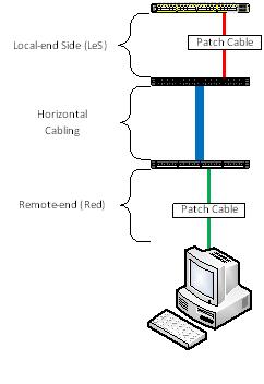
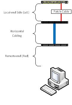
- Local-end Side (LeS) patch cable;
- Local-end Side (LeS) patch panel (including punch block);
- Horizontal cable;
- Remote-end (Red) patch panel (including punch block);
- Remote-end (Red) patch cable; and
- Remote-end (Red) device NIC
So you see, dear readers, TDR minimize the guess-work.
Picture this …
Before we begin, let me give you the “lay of the land”. Presume the following scenario:
What model of Cisco switch does TDR work on?
Firstly, not all switch model support TDR. TDR feature first came out with the Catalyst 2960. So here is the list of which ones will work and will not:
|
Model |
TDR Support |
|
2960 |
Yes1, 2 |
|
2960G |
Yes |
|
2960S |
Yes |
|
2918 |
Unknown |
|
2350 |
Unknown |
|
2360 |
Unknown |
|
2975 |
Unknown |
|
3560 |
No |
|
3560G |
Yes |
|
3560E/3560X |
Yes |
|
3750 |
No |
|
3750G |
Yes |
|
3750E/3750X |
Yes |
|
Nexus 2K |
Unknown |
|
Nexus 5K |
Unknown |
|
Nexus 7K |
Yes3 |
|
Sup7E/X4548 |
Yes |
Note:
- 1. The 2960 will support TDR in both the FastEthernet and dual-personality GigiabitEthernet port, however, when used on a FastEthernet port, TDR will only test the first two pairs, namely Pairs A & B. For obvious reasons, Pairs C and D will not be tested when used on non-GigabitEthernet ports.
- 2. Except the WS-C2960-48PDL, when using the copper GigabitEthernet port of the Catalyst 2960, one must manually set the interface to copper using the command “media rj” before the test can be conducted.
- 3. Confirmed by Cisco TAC, Ankur Garg.
The list does not include modules/blades for the Catalyst 4000/4500, 5000/5500, 6000/6500 although it is mentioned here that TDR was introduced with IOS Release 12.2 ZY for the Catalyst 6000/6500. It’s not included in the list above because I don’t have the resources to test and verify.
Legacy Cisco Catalyst models 1900, 2900XL/3500XL, 2940/2950/2955, 2948G and 2970 are not supported. Routers are also not supported. I do not have any resources to test router Ethernet Switch Modules (NME, HWIC, EHWIC). Wireless Access Points do not support TDR.
Why doesn’t the FastEthernet-flavoured 3560 and 3750 support TDR and but the cheaper FastEthernet 2960 support TDR?
Base on the time-line, the “plain” (or non-GigabitEthernet copper port) 3560 and 3750 came out BEFORE the 2960. The “chip” for the TDR was included in the design of the 2960. When Cisco released the 3560G and 3750G later, someone made the ultimate decision to include the TDR feature as a standard. Therefore, the plain 3560 and 3750 are the only two series that WON’T HAVE the TDR feature. (Take note reader: Emphasis on the words “WON’T HAVE”)
Any Gotchas I need to be aware of?
- Switches need to run IOS version 12.2 or later. TDR is supported in IOS version 15.0. IOS version 12.0 and 12.1 do NOT support TDR.
- If you are running IOS version 12.2(46)SE or earlier, TDR test is DISRUPTIVE. During the test, the interface will go down and up. For obvious reasons, anything connected will lose network connectivity.
- If the remote-end device is a power-over-ethernet (PoE) device, the test will cause the device to lose power. If you have, for example, a Voice over IP (VoIP) phone and a PC client is connected to the phone, both the phone and client will lose network connectivity because the phone does not have a bypass functionality. This will affect ALL IOS versions.
- Particularly when you are running old IOS versions, the test can take between five (5) to seven (7) seconds.
- TDR works on 10/100/1000BaseTx. Fibre optic ports (any flavours) is not covered/discussed here. TenGigabitEthernet copper port DOES NOT (YET) support TDR.
- Cisco GLC-T/GLC-TX SFP module does NOT support TDR.
The next two Gotcha items are for those who plan to use the TDR feature on Cisco Catalyst 2960 and 2960G (2960S not included):
- 1. The 2960 will support TDR in both the FastEthernet and dual-personality GigiabitEthernet port, however, when used on a FastEthernet port, TDR will only test the first two pairs, namely Pairs A & B. For obvious reasons, Pairs C and D will not be tested when used on non-GigabitEthernet ports. Pairs C and D will report a result of “Not Supported”.
- 2. Except the WS-C2960-48PDL, when using the copper GigabitEthernet (Gig 0/1 and Gig 0/2) ports of the Catalyst 2960, one must manually set the interface to copper using the command “media rj” before the test can be conducted.
How to use TDR?
The commands are very simple: One to start the test and the second command to display the result. Here is simple procedure:
- Command to start the TDR: “test cable tdr interface <interface of your choice>”;
- Wait for about 5 to 7 seconds for the test to run; and
- Command to show the result of the TDR test: “show cable tdr interface <interface of your choice>”
See? Easy! Now let’s see what the I results would look like.
|
Interface |
Speed |
Local pair |
Pair length |
Remote pair |
Pair status |
|
Gi0/1 |
1000M |
Pair A |
3 +/- 1 meters |
Pair A |
Normal |
|
Pair B |
3 +/- 1 meters |
Pair B |
Normal |
||
|
Pair C |
3 +/- 1 meters |
Pair C |
Normal |
||
|
Pair D |
3 +/- 1 meters |
Pair D |
Normal |
So what does this result above tell us?
- Port tested is on GigabitEthernet 0/1;
- Port has negotiated to 1 Gbps;
- Cable use is a straight-through cable (look and compare the values of “Local pair” and “remote pair”);
- Cable length is approximately 3 metres long and an error (length-wise) of 1 metre; and
- All four pairs are working fine (Pair status)
Under “Pair status” you can get the following results:
|
Result |
Explaination |
|
Normal |
Ideal result you want.
|
|
Open |
Open circuit. This means that one (or more) pair has “no pin contact”. |
|
Short |
Short circuit. |
|
Impedance Mismatched |
Bad cable. For more explanation, go here. |
An ideal result is “Normal”. In practice, whether the remote-end device is FastEthernet or GigabitEthernet, I will never accept a TDR result other than “Normal” in all four pairs.
Cable Pairs explained?
This is how I see what each Pairs control:
|
Pairs |
Function |
|
A |
This pair controls whether or not the port should go up or down. |
|
B |
Protocol-level and controls FastEthernet. |
|
C |
Power over Ethernet (PoE) |
|
D |
GigabitEthernet |
More examples
|
Interface |
Speed |
Local pair |
Pair length |
Remote pair |
Pair status |
|
Gi0/11 |
100M |
Pair A |
13 +/- 1 meters |
Pair B |
Normal |
|
Pair B |
12 +/- 1 meters |
Pair A |
Normal |
||
|
Pair C |
0 +/- 1 meters |
Pair D |
Open |
||
|
Pair D |
0 +/- 1 meters |
Pair C |
Open |
Normally, this result would freak me out. Look at the items in RED. Pairs C and D are reporting a cable value of “0”. Next I move to the “Pair status” and it’s reported as an Open circuit. No pin contact. Whao! But look at the speed. It’s 100 Mbps. So it’s normal … I guess.
But wait. What if the remote-end side (Red) client is a GigabitEthernet. So where is the faulty cabling? Which one of the patch cables? Or is it a horizontal cabling? Does the client support GigabitEthernet or not?
Here’s another clue: Look at the length of the cable for Pair A and B. It’s reporting around 12 to 13 metres. Experience has taught me that my Local-end Side (LeS) cable doesn’t exceed two metres. So that rules out my cable, however the horizontal cabling is more than 10 metres. So what’s between the horizontal cabling and the remote-end client? You have three suspects: 1) The remote-end punch block; 2) the remote-end patch cable; and 3) remote-end client.
Culprit was the remote-end punch block and the horizontal cabling: Cable contractors only terminated two pairs.
Never ask a boy to do a man’s job!
|
Interface |
Speed |
Local pair |
Pair length |
Remote pair |
Pair status |
|
Gi1/0/48 |
auto |
Pair A |
149 +/- 1 meters |
Pair B |
Normal |
|
Pair B |
151 +/- 1 meters |
Pair A |
Normal |
||
|
Pair C |
35 +/- 1 meters |
Pair D |
Short/Impedance Mism |
||
|
Pair D |
21 +/- 1 meters |
Pair C |
Short/Impedance Mism |
Its results like the ones above that makes me want to cry.
Ok, I look under “Pair status” and I see “Short/Impedance Mism” for Pair C and D. No question about it. It’s bad cabling. This is not what makes me want to cry. Look at under “Pair length” of Pair A and B. NOW cry.
Should I be worried?
|
Interface |
Speed |
Local pair |
Pair length |
Remote pair |
Pair status |
|
Fa0/39 |
100M |
Pair A |
6 +/- 1 meters |
N/A |
Open |
|
Pair B |
49 +/- 1 meters |
N/A |
Open |
||
|
Pair C |
N/A |
N/A |
Not Supported |
||
|
Pair D |
N/A |
N/A |
Not Supported |
Looking at the result, I can confidently say that the appliance was a 48-port Cisco Catalyst 2960. How? Look under “Interface”. Look at “Pair status” for Pair C and D. Only the plain 2960 FastEthernet ports can support TDR.
But look at “Pair status” for Pairs A and B. What does that mean?
It means that the remote-end (Red) patch cable is missing.
Weird things have happened before
I’ve taken the opportunity to do limited testing on TDR on a 4510R+E. The chassis has a Sup7E and with a X4548-RJ45V+ line card (IOS version 03.01.01.SG). The result(s) are very, very weird. Oh, by the way, the TDR testing on this setup takes 60 seconds. 60 seconds! Good grief! I have no idea whether the Sup7E or the line card is the factor.
The sample below is coming from a GOOD cable:
|
Interface |
Speed |
Local pair |
Pair length |
Remote pair |
Pair status |
|
Gi2/36 |
1Gbps |
1-2 |
29 +/-10m |
Unknown |
Fault |
|
3-6 |
30 +/-10m |
Unknown |
Fault |
||
|
4-5 |
29 +/-10m |
Unknown |
Fault |
||
|
7-8 |
30 +/-10m |
Unknown |
Fault |
And the sample below is coming from a BAD cable:
|
Interface |
Speed |
Local pair |
Pair length |
Remote pair |
Pair status |
|
Gi2/37 |
0Mbps |
1-2 |
56 +/-10m |
Unknown |
Fault |
|
3-6 |
0 m |
Unknown |
Fault |
||
|
4-5 |
56 +/-10m |
Unknown |
Fault |
||
|
7-8 |
59 +/-10m |
Unknown |
Fault |
As you can see, whether or not you have a good or a bad cable the result from the “Remote pair” and “Status” can be deceiving. The ONLY WAY to determine if you have a bad cable issue or not is to look at the “Speed” and the output to the “Pair length”.
I am suspecting that the misleading result of the “Remote pair” and the “Pair status” is an IOS bug.
(25 August 2023) IMPORTANT ADDENDUM:
Starting with IOS-XE (aka Polaris) version 16.X.X (and later), TDR is completely broken. I strongly urge people to stop relying TDR results from Catalyst switches if platform is running 16.X.X (and later), 17.X.X (and later) because the result is neither accurate nor reliable. The Bug IDs are: CSCvw97924 & CSCwd97177
Screenshots (below) of broken TDR results:


-- END OF TRANSMISSION --
- Mark as Read
- Mark as New
- Bookmark
- Permalink
- Report Inappropriate Content
Hi all,
same issue here with an Unify OpenStage 40G POE.
On a 2960X it just negotiates at 100M showing following results :
Interface Speed Local pair Pair length Remote pair Pair status
--------- ----- ---------- ------------------ ----------- --------------
Gi1/0/19 100M Pair A N/A Pair B Normal
Pair B 2 +/- 10 meters Pair A Short
Pair C 2 +/- 10 meters Pair C Open
Pair D 2 +/- 10 meters Pair D Open
Tried different Ports, reboot, etc. with no Change.
Same Phone, same Cable on a 2960S negotiates at 1000 with all Pair Status showing normal.
Tried different IOS Versions 15.2(2)E3, 15.2(2)E6, 15.2(4)E3 on the 2960X, all with the same result.
Different IP Phone same results.
Any clues ?
- Mark as Read
- Mark as New
- Bookmark
- Permalink
- Report Inappropriate Content
Don't worry about Pair A.
The fault is with Pairs B, C & D and it's closest to the switch port.
Try plugging the phone directly straight to the switch port using the same cable.
Just as a note, starting with the 2960X (tested with 3850), the way TDR is handled is "weird".
The 2960X will test all pairs. If a pair is good, then then distance will be "N/A" or (depending on IOS version) "0". If there is a fault in a pair, the fault and distance will be displayed.
I honestly don't know the logic behind this change of direction.
- Mark as Read
- Mark as New
- Bookmark
- Permalink
- Report Inappropriate Content
Hi Leo,
thank you for your answer.
I forgot to mention that the cable is always plugged in directly to the Switchport.
I thought the issue has to be at the IP Phone, since there are several others connected to the 2960X without Problems. But since this one (brand new) works perfectly on the 2960S with the same cable but not on the 2960X I am lost. The Phone was already replaced by the supplier with no change at all.
- Mark as Read
- Mark as New
- Bookmark
- Permalink
- Report Inappropriate Content
Hi Leo
An excellent post - I've learn't something really useful.
Slightly frustrating is that while the Cisco 2960X's running c2960x-universalk9-mz.152-2.E5 seem to support this function, the results are hit and miss, more often returning a result of "not completed".
My initial "googling" makes me wonder if we are hitting CSCtl71772 although the 2960X is not listed as affected. I can go to two identical switches in the same stack, on one the TDR test seems to work as advertised, the second stack member reports "not completed" against every port tested. We haven't got that many cable faults - I hope :-(.
From my own observations, if I run the TDR test on a port with a Cisco 7941G IP phone connected, it is indeed disruptive. The phone shows "ethernet disconnected" and then appears to reset.
If I run the same test on a port with my Cisco 7971GE co-located with my notebook, neither indicate a loss of connectivity. I assume this is related to a Gig capable device on a Gig port versus 100Mb capable device on a Gig port.
Excellent article non the less. Thanks for sharing.
Best
Richard
- Mark as Read
- Mark as New
- Bookmark
- Permalink
- Report Inappropriate Content
Thanks for the comment, Richard.
I've got some depressing news: The TDR function of the 2960X, 3650 and 3850 have now changed. Here are the conditions:
1. If a pair is OK, the switch will produce a distance of "0". The switch will NOT test for the distance of the cable;
2. If a pair is not OK, then it will produce the distance as well as the reason of the fault.
If you (or anyone) think this new "behaviour" is not satisfactory, raise this issue with your Cisco SE/AM and demand they raise a PER (Product Enhancement Request).
- Mark as Read
- Mark as New
- Bookmark
- Permalink
- Report Inappropriate Content
HI Leo, the changes you mention for the 2960X does that only apply from a specific Firmware?
- Mark as Read
- Mark as New
- Bookmark
- Permalink
- Report Inappropriate Content
Hi Leo
That is indeed "sub-optimal". Curiously I've re-run the tests on one of our 2960X stacks and get these results:-
Results run on 2960X with Cisco 7945 1Gb phone connected
Interface Speed Local pair Pair length Remote pair Pair status
--------- ----- ---------- ------------------ ----------- --------------------
Gi1/0/38 1000M Pair A 78 +/- 10 meters Pair A Normal
Pair B 78 +/- 10 meters Pair B Normal
Pair C 78 +/- 10 meters Pair C Normal
Pair D 78 +/- 10 meters Pair D Normal
Results run on 2960X with 7941G 100Mb phone connected
Interface Speed Local pair Pair length Remote pair Pair status
--------- ----- ---------- ------------------ ----------- --------------------
Gi1/0/6 100M Pair A N/A N/A Not Completed
Pair B N/A N/A Not Completed
Pair C N/A N/A Not Completed
Pair D N/A N/A Not Completed
Results on same interface with phone disconnected but drop lead still in place (note pair D appear 1M longer)
Interface Speed Local pair Pair length Remote pair Pair status
--------- ----- ---------- ------------------ ----------- --------------------
Gi1/0/6 auto Pair A 57 +/- 10 meters N/A Open
Pair B 57 +/- 10 meters N/A Open
Pair C 57 +/- 10 meters N/A Open
Pair D 58 +/- 10 meters N/A Open
I ran the same test with the drop lead removed and the distance shortened by 2 meters so the TDR is surprisingly accurate.
Cheers
Rich
- Mark as Read
- Mark as New
- Bookmark
- Permalink
- Report Inappropriate Content
the changes you mention for the 2960X does that only apply from a specific Firmware?
For the 2960X, yes it is all versions. For the 3650/3850, then it will depend on the version. I know for a fact that 2960X is meant to do this because when they gave me a beta to test TDR (after the function wasn't enabled in early firmware versions) this was the "caveat umptor" the Cisco SE told me.
Again, I have no idea why the developers made this sort of decision (a limitation with the chipset, maybe?).
- Mark as Read
- Mark as New
- Bookmark
- Permalink
- Report Inappropriate Content
Hello Leo
Very informative - cheers
- Mark as Read
- Mark as New
- Bookmark
- Permalink
- Report Inappropriate Content
Hello Leo,
Thank you very much for this information. I saw a similar post to my current issue but I wanted to see if I can please get some feedback on mine since it is a bit different?
Current issue is with a few VOIP Cisco phone devices. The Corporate Directory sometimes is not functional and the only way to resolve this is by a hard power cycle of the devices. All devices (about 7) are located in the same building, different switches. All device logs indicate a possible issue with the network. I am getting a lot of TCP-timeouts, KeepaliveTO, etc errors for all the devices been effected.
However, users are not reporting that the devices are rebooting or loosing power....The reason that I think the users are not reporting the devices loosing power is because the devices are going into fail-over mode. But anyways, just wanted to give you a little background information.
I decided to run some TDR cable testing on each device after reviewing the device logs.
These two are on the same switch:
Switch Ports Model SW Version SW Image
------ ----- ----- ---------- ----------
* 1 52 WS-C2960S-48FPS-L 12.2(55)SE8 C2960S-UNIVERSALK9-M
Interface Speed Local pair Pair length Remote pair Pair status
--------- ----- ---------- ------------------ ----------- --------------------
Gi1/0/29 100M Pair A 27 +/- 0 meters N/A Normal
Pair B 25 +/- 0 meters N/A Normal
Pair C 27 +/- 1 meters N/A Short/Crosstalk
Pair D 27 +/- 1 meters N/A Short/Crosstalk
Interface Speed Local pair Pair length Remote pair Pair status
--------- ----- ---------- ------------------ ----------- --------------------
Gi1/0/21 100M Pair A 24 +/- 0 meters N/A Normal
Pair B 24 +/- 0 meters N/A Normal
Pair C 25 +/- 1 meters N/A Short/Crosstalk
Pair D 25 +/- 1 meters N/A Short/Crosstalk
This devices in on a different switch, different floor, same building:
Switch Ports Model SW Version SW Image
------ ----- ----- ---------- ----------
* 1 52 WS-C2960S-48FPS-L 12.2(55)SE8 C2960S-UNIVERSALK9-M
Interface Speed Local pair Pair length Remote pair Pair status
--------- ----- ---------- ------------------ ----------- --------------------
Gi1/0/36 100M Pair A 47 +/- 0 meters N/A Normal
Pair B 47 +/- 0 meters N/A Normal
Pair C 47 +/- 1 meters N/A Short/Crosstalk
Pair D 47 +/- 1 meters N/A Short/Crosstalk
What I am having issues understand is why does the Remote Pair report "N/A" for all interfaces?
Also, just based on the results from Pair C and D for all interfaces is it pretty safe to assuming there is a problem with cabling?
I can't find anything explain what "Crosstalk" indicates. It sounds pretty straight forward on what it is but would still like to know the Cisco definition for it.
Thank you very much.
- Mark as Read
- Mark as New
- Bookmark
- Permalink
- Report Inappropriate Content
")
")
- Mark as Read
- Mark as New
- Bookmark
- Permalink
- Report Inappropriate Content
1) "Crosstalk" means that a signal put on one wire can be measured on another wire(where it is not supposed to be.
(like left audio signal can be heard in the background on the right audio speaker)
as such a short produces 100% crosstalk
2) 12.2(55)SE8 was released 28-Jun-2013
-> time to think about an upgrade?
3) based on the results from Pair C and D for all interfaces...
-> (in addition to 2) ) try to test an unconnected port fist, use this output for pairs C and D as baseline
additional steps you can perform to compare output with before you declare all cables as faulty
- patch-cable in the switchport only
- patch-cable in the switchport directly into phone
- patch-cable + horizontal cabling
- patch-cable + horizontal cabling + pach-cable
- patch-cable + horizontal cabling _ patch-cable + phone
@Leo Laohoo: great article,
I do have an electrical engineering knowledge, but with your explanation this is no requirement at all
I used TDR sometimes before, but your info is a great addition to my understanding of how switches use this measurement tool
- Mark as Read
- Mark as New
- Bookmark
- Permalink
- Report Inappropriate Content
Does anyone have any input in the "validity" of the TDR results performed from the CLI on a SF352-08MP switch ?
Reading the "Administration guide" for the device (350, 350X and 550X series) it mentions this feature should be available through the web interface, but it's not, not even after updating to the latest firmware. However, through the CLI it's availble, but when running it I get a quite simplified output compared to what many other have posted in this thread before me (no infomration about pairs, etc).
E.g. ("log" of running test with cable connected to a device, then with cable plugged out, and then with cable plugged in again)
switchcd5e53#test cable-diagnostics tdr interface fa1
.06-May-2020 06:11:52 %LINK-W-Down:  fa1
06-May-2020 06:11:52 %LINK-W-Down:  Vlan 1
.
Cable on port fa1 is good
switchcd5e53#06-May-2020 06:11:54 %LINK-I-Up:  fa1
06-May-2020 06:11:54 %LINK-I-Up:  Vlan 1
06-May-2020 06:11:59 %STP-W-PORTSTATUS: fa1: STP status Forwarding
06-May-2020 06:12:02 %LINK-W-Down:  fa1
06-May-2020 06:12:02 %LINK-W-Down:  Vlan 1
switchcd5e53#test cable-diagnostics tdr interface fa1
..
Cable on port fa1 is not connected
switchcd5e53#show cable-diagnostics tdr interface fa1

   Port       Result    Length [meters]             Date
----------- ----------- ---------------- --------------------------
    fa1      No cable          0           06-May-2020 06:12:13

switchcd5e53#06-May-2020 06:12:36 %AAA-I-DISCONNECT: http connection for user cisco, source 192.168.1.2 destination 192.168.1.254 TERMINATED
06-May-2020 06:12:39 %LINK-I-Up:  fa1
06-May-2020 06:12:39 %LINK-I-Up:  Vlan 1
switchcd5e53#test cable-diagnostics tdr interface fa1
06-May-2020 06:12:43 %STP-W-PORTSTATUS: fa1: STP status Forwarding
.06-May-2020 06:12:49 %LINK-W-Down:  fa1
06-May-2020 06:12:49 %LINK-W-Down:  Vlan 1
.
Cable on port fa1 is good
switchcd5e53#show cable-diagnostics tdr interface fa1

   Port       Result    Length [meters]             Date
----------- ----------- ---------------- --------------------------
    fa1         OK
Just unsure about if I should put much into the output of this function as I still consider the switch to be an "entry-level" one and thus don't have the biggest expectations when it comes to what kind of features it supports and the quality of them.

")
- Mark as Read
- Mark as New
- Bookmark
- Permalink
- Report Inappropriate Content
Just bored this morning and decided i wanted to know for sure which pair is which. Tested on a 2960x 15.0(2)EX5. with an open cable terminated TIA568-B to the switch.
I then shorted individual pairs to identify them.
Pair A - Orange/OrWhite pins 1,2
Pair B - Green/GrWhite pins 3,6
Pair C - Blue/BlWhite pins 4,5
Pair D - Brown/BrWhite pins 7,8
When shorting individual pairs Orange/GrWhite or Green/OrWhite Orange/Green or OrWhite/GrWhite I got the results below
Gi1/0/2 auto
Pair A 11 +/- 10 meters N/A Short/Crosstalk
Pair B 11 +/- 10 meters N/A Open
Pair C 11 +/- 10 meters N/A Open
Pair D 11 +/- 10 meters N/A Open
Shorted BOTH Orange/GrWhite and Green/OrWhite or Orange/Green and OrWhite/GrWhite and always got the same result.
Pair A     11   +/- 10 meters N/A         Short/Crosstalk
Pair B     11   +/- 10 meters N/A         Short/Crosstalk
Pair C     11   +/- 10 meters N/A         Open
Pair D     11   +/- 10 meters N/A         Open
No matter if I shorted individual pairs or any combination between the Orange/OrWhite and the Blue/BlWhite Pairs I got the result below.
Pair A     11   +/- 10 meters N/A         Short/Crosstalk
Pair B     11   +/- 10 meters N/A         Open
Pair C     11   +/- 10 meters N/A         Short/Crosstalk
Pair D     11   +/- 10 meters N/A         Open
I think the results may be the same for Blue to Brown shorts as Blue and Orange but the combinations would fill this post.
Hope this helps.
- Mark as Read
- Mark as New
- Bookmark
- Permalink
- Report Inappropriate Content
of course if properly cabled Orange/OrWhite and the Blue/BlWhite are pairs in the cable
see examples this document gives a clue about pins and pairs on this device:
1-2 1 +/- 6 m N/A Pair B Terminated
3-4 1 +/- 6 m N/A Pair A Terminated
5-6 1 +/- 6 m N/A Pair C Terminated
7-8 1 +/- 6 m N/A Pair D Terminated
strangely it does not show 1-2 and 3-6 as pairs........
added: this document tells not to view at the pairs individually!
TDR operates across four wires.
Depending on the cable conditions, the status might show that one pair is OPEN or SHORT while all other wire pairs display as faulty.
This operation is acceptable because you should declare a cable faulty provided one pair of wires is either OPEN or SHORT.
Find answers to your questions by entering keywords or phrases in the Search bar above. New here? Use these resources to familiarize yourself with the community: