- Cisco Community
- Technology and Support
- Networking
- Networking Knowledge Base
- How to use Time-Domain Reflectometer (TDR)
- Subscribe to RSS Feed
- Mark as New
- Mark as Read
- Bookmark
- Subscribe
- Printer Friendly Page
- Report Inappropriate Content
- Subscribe to RSS Feed
- Mark as New
- Mark as Read
- Bookmark
- Subscribe
- Printer Friendly Page
- Report Inappropriate Content
10-11-2011 02:57 PM - edited 08-24-2023 05:01 PM
I’m no electrical engineer, (the closest experience I have with electricity is the amount of electrocution I received when I was a child [due to faulty cabling of electrical appliances]) so I will spare readers technical jargons and boring formulas because this guide is not aimed to be published in the International Journal of Mumbo-Jumbo. This guide is to help anyone how to confidently use the TDR feature when troubleshooting basic Layer 1 Ethernet issue.
My knowledge with this feature is based entirely on experience and a lot of trial-and-error.
What is Time-Domain Reflectometer (TDR)?
“A time-domain reflectometer (TDR) is an electronic instrument used to characterize and locate faults in metallic cables (for example, twisted wire pairs, coaxial cables)1.”
For the sake of this document, “TDR testing” and “TDR” are used interchangeably to sow confusion to the un-initiated. They both mean the same.
How can TDR help me?
TDR, in its simplest form, can help you determine IF you have a cable problem, WHICH pair(s) is/are faulty and HOW FAR away the fault is.
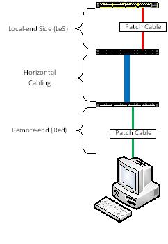
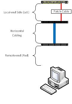
Typically, when you have a Layer 1 issue there are a lot of factors to consider:
- Local-end Side (LeS) patch cable;
- Local-end Side (LeS) patch panel (including punch block);
- Horizontal cable;
- Remote-end (Red) patch panel (including punch block);
- Remote-end (Red) patch cable; and
- Remote-end (Red) device NIC
So you see, dear readers, TDR minimize the guess-work.
Picture this …
Before we begin, let me give you the “lay of the land”. Presume the following scenario:
What model of Cisco switch does TDR work on?
Firstly, not all switch model support TDR. TDR feature first came out with the Catalyst 2960. So here is the list of which ones will work and will not:
|
Model |
TDR Support |
|
2960 |
Yes1, 2 |
|
2960G |
Yes |
|
2960S |
Yes |
|
2918 |
Unknown |
|
2350 |
Unknown |
|
2360 |
Unknown |
|
2975 |
Unknown |
|
3560 |
No |
|
3560G |
Yes |
|
3560E/3560X |
Yes |
|
3750 |
No |
|
3750G |
Yes |
|
3750E/3750X |
Yes |
|
Nexus 2K |
Unknown |
|
Nexus 5K |
Unknown |
|
Nexus 7K |
Yes3 |
|
Sup7E/X4548 |
Yes |
Note:
- 1. The 2960 will support TDR in both the FastEthernet and dual-personality GigiabitEthernet port, however, when used on a FastEthernet port, TDR will only test the first two pairs, namely Pairs A & B. For obvious reasons, Pairs C and D will not be tested when used on non-GigabitEthernet ports.
- 2. Except the WS-C2960-48PDL, when using the copper GigabitEthernet port of the Catalyst 2960, one must manually set the interface to copper using the command “media rj” before the test can be conducted.
- 3. Confirmed by Cisco TAC, Ankur Garg.
The list does not include modules/blades for the Catalyst 4000/4500, 5000/5500, 6000/6500 although it is mentioned here that TDR was introduced with IOS Release 12.2 ZY for the Catalyst 6000/6500. It’s not included in the list above because I don’t have the resources to test and verify.
Legacy Cisco Catalyst models 1900, 2900XL/3500XL, 2940/2950/2955, 2948G and 2970 are not supported. Routers are also not supported. I do not have any resources to test router Ethernet Switch Modules (NME, HWIC, EHWIC). Wireless Access Points do not support TDR.
Why doesn’t the FastEthernet-flavoured 3560 and 3750 support TDR and but the cheaper FastEthernet 2960 support TDR?
Base on the time-line, the “plain” (or non-GigabitEthernet copper port) 3560 and 3750 came out BEFORE the 2960. The “chip” for the TDR was included in the design of the 2960. When Cisco released the 3560G and 3750G later, someone made the ultimate decision to include the TDR feature as a standard. Therefore, the plain 3560 and 3750 are the only two series that WON’T HAVE the TDR feature. (Take note reader: Emphasis on the words “WON’T HAVE”)
Any Gotchas I need to be aware of?
- Switches need to run IOS version 12.2 or later. TDR is supported in IOS version 15.0. IOS version 12.0 and 12.1 do NOT support TDR.
- If you are running IOS version 12.2(46)SE or earlier, TDR test is DISRUPTIVE. During the test, the interface will go down and up. For obvious reasons, anything connected will lose network connectivity.
- If the remote-end device is a power-over-ethernet (PoE) device, the test will cause the device to lose power. If you have, for example, a Voice over IP (VoIP) phone and a PC client is connected to the phone, both the phone and client will lose network connectivity because the phone does not have a bypass functionality. This will affect ALL IOS versions.
- Particularly when you are running old IOS versions, the test can take between five (5) to seven (7) seconds.
- TDR works on 10/100/1000BaseTx. Fibre optic ports (any flavours) is not covered/discussed here. TenGigabitEthernet copper port DOES NOT (YET) support TDR.
- Cisco GLC-T/GLC-TX SFP module does NOT support TDR.
The next two Gotcha items are for those who plan to use the TDR feature on Cisco Catalyst 2960 and 2960G (2960S not included):
- 1. The 2960 will support TDR in both the FastEthernet and dual-personality GigiabitEthernet port, however, when used on a FastEthernet port, TDR will only test the first two pairs, namely Pairs A & B. For obvious reasons, Pairs C and D will not be tested when used on non-GigabitEthernet ports. Pairs C and D will report a result of “Not Supported”.
- 2. Except the WS-C2960-48PDL, when using the copper GigabitEthernet (Gig 0/1 and Gig 0/2) ports of the Catalyst 2960, one must manually set the interface to copper using the command “media rj” before the test can be conducted.
How to use TDR?
The commands are very simple: One to start the test and the second command to display the result. Here is simple procedure:
- Command to start the TDR: “test cable tdr interface <interface of your choice>”;
- Wait for about 5 to 7 seconds for the test to run; and
- Command to show the result of the TDR test: “show cable tdr interface <interface of your choice>”
See? Easy! Now let’s see what the I results would look like.
|
Interface |
Speed |
Local pair |
Pair length |
Remote pair |
Pair status |
|
Gi0/1 |
1000M |
Pair A |
3 +/- 1 meters |
Pair A |
Normal |
|
Pair B |
3 +/- 1 meters |
Pair B |
Normal |
||
|
Pair C |
3 +/- 1 meters |
Pair C |
Normal |
||
|
Pair D |
3 +/- 1 meters |
Pair D |
Normal |
So what does this result above tell us?
- Port tested is on GigabitEthernet 0/1;
- Port has negotiated to 1 Gbps;
- Cable use is a straight-through cable (look and compare the values of “Local pair” and “remote pair”);
- Cable length is approximately 3 metres long and an error (length-wise) of 1 metre; and
- All four pairs are working fine (Pair status)
Under “Pair status” you can get the following results:
|
Result |
Explaination |
|
Normal |
Ideal result you want.
|
|
Open |
Open circuit. This means that one (or more) pair has “no pin contact”. |
|
Short |
Short circuit. |
|
Impedance Mismatched |
Bad cable. For more explanation, go here. |
An ideal result is “Normal”. In practice, whether the remote-end device is FastEthernet or GigabitEthernet, I will never accept a TDR result other than “Normal” in all four pairs.
Cable Pairs explained?
This is how I see what each Pairs control:
|
Pairs |
Function |
|
A |
This pair controls whether or not the port should go up or down. |
|
B |
Protocol-level and controls FastEthernet. |
|
C |
Power over Ethernet (PoE) |
|
D |
GigabitEthernet |
More examples
|
Interface |
Speed |
Local pair |
Pair length |
Remote pair |
Pair status |
|
Gi0/11 |
100M |
Pair A |
13 +/- 1 meters |
Pair B |
Normal |
|
Pair B |
12 +/- 1 meters |
Pair A |
Normal |
||
|
Pair C |
0 +/- 1 meters |
Pair D |
Open |
||
|
Pair D |
0 +/- 1 meters |
Pair C |
Open |
Normally, this result would freak me out. Look at the items in RED. Pairs C and D are reporting a cable value of “0”. Next I move to the “Pair status” and it’s reported as an Open circuit. No pin contact. Whao! But look at the speed. It’s 100 Mbps. So it’s normal … I guess.
But wait. What if the remote-end side (Red) client is a GigabitEthernet. So where is the faulty cabling? Which one of the patch cables? Or is it a horizontal cabling? Does the client support GigabitEthernet or not?
Here’s another clue: Look at the length of the cable for Pair A and B. It’s reporting around 12 to 13 metres. Experience has taught me that my Local-end Side (LeS) cable doesn’t exceed two metres. So that rules out my cable, however the horizontal cabling is more than 10 metres. So what’s between the horizontal cabling and the remote-end client? You have three suspects: 1) The remote-end punch block; 2) the remote-end patch cable; and 3) remote-end client.
Culprit was the remote-end punch block and the horizontal cabling: Cable contractors only terminated two pairs.
Never ask a boy to do a man’s job!
|
Interface |
Speed |
Local pair |
Pair length |
Remote pair |
Pair status |
|
Gi1/0/48 |
auto |
Pair A |
149 +/- 1 meters |
Pair B |
Normal |
|
Pair B |
151 +/- 1 meters |
Pair A |
Normal |
||
|
Pair C |
35 +/- 1 meters |
Pair D |
Short/Impedance Mism |
||
|
Pair D |
21 +/- 1 meters |
Pair C |
Short/Impedance Mism |
Its results like the ones above that makes me want to cry.
Ok, I look under “Pair status” and I see “Short/Impedance Mism” for Pair C and D. No question about it. It’s bad cabling. This is not what makes me want to cry. Look at under “Pair length” of Pair A and B. NOW cry.
Should I be worried?
|
Interface |
Speed |
Local pair |
Pair length |
Remote pair |
Pair status |
|
Fa0/39 |
100M |
Pair A |
6 +/- 1 meters |
N/A |
Open |
|
Pair B |
49 +/- 1 meters |
N/A |
Open |
||
|
Pair C |
N/A |
N/A |
Not Supported |
||
|
Pair D |
N/A |
N/A |
Not Supported |
Looking at the result, I can confidently say that the appliance was a 48-port Cisco Catalyst 2960. How? Look under “Interface”. Look at “Pair status” for Pair C and D. Only the plain 2960 FastEthernet ports can support TDR.
But look at “Pair status” for Pairs A and B. What does that mean?
It means that the remote-end (Red) patch cable is missing.
Weird things have happened before
I’ve taken the opportunity to do limited testing on TDR on a 4510R+E. The chassis has a Sup7E and with a X4548-RJ45V+ line card (IOS version 03.01.01.SG). The result(s) are very, very weird. Oh, by the way, the TDR testing on this setup takes 60 seconds. 60 seconds! Good grief! I have no idea whether the Sup7E or the line card is the factor.
The sample below is coming from a GOOD cable:
|
Interface |
Speed |
Local pair |
Pair length |
Remote pair |
Pair status |
|
Gi2/36 |
1Gbps |
1-2 |
29 +/-10m |
Unknown |
Fault |
|
3-6 |
30 +/-10m |
Unknown |
Fault |
||
|
4-5 |
29 +/-10m |
Unknown |
Fault |
||
|
7-8 |
30 +/-10m |
Unknown |
Fault |
And the sample below is coming from a BAD cable:
|
Interface |
Speed |
Local pair |
Pair length |
Remote pair |
Pair status |
|
Gi2/37 |
0Mbps |
1-2 |
56 +/-10m |
Unknown |
Fault |
|
3-6 |
0 m |
Unknown |
Fault |
||
|
4-5 |
56 +/-10m |
Unknown |
Fault |
||
|
7-8 |
59 +/-10m |
Unknown |
Fault |
As you can see, whether or not you have a good or a bad cable the result from the “Remote pair” and “Status” can be deceiving. The ONLY WAY to determine if you have a bad cable issue or not is to look at the “Speed” and the output to the “Pair length”.
I am suspecting that the misleading result of the “Remote pair” and the “Pair status” is an IOS bug.
(25 August 2023) IMPORTANT ADDENDUM:
Starting with IOS-XE (aka Polaris) version 16.X.X (and later), TDR is completely broken. I strongly urge people to stop relying TDR results from Catalyst switches if platform is running 16.X.X (and later), 17.X.X (and later) because the result is neither accurate nor reliable. The Bug IDs are: CSCvw97924 & CSCwd97177
Screenshots (below) of broken TDR results:


-- END OF TRANSMISSION --
- Mark as Read
- Mark as New
- Bookmark
- Permalink
- Report Inappropriate Content
Thanks George. I'm gonna be famous! LOL!
- Mark as Read
- Mark as New
- Bookmark
- Permalink
- Report Inappropriate Content
Great article! I have a feeling I just created a lot of work ahead of me. 2 of the 3 ports I ran it on showed problems! One was my IT Director's, and it left me a bit confused. Output on Pair C gives a length, a remote pair, but says its open. His POE and GigE work fine. His A and B pairs also show swapped. What does this mean?
version is 12.2(55)SE1 on a C3750G
Interface Speed Local pair Pair length Remote pair Pair status
--------- ----- ---------- ------------------ ----------- --------------------
Gi2/0/34 1000M Pair A 15 +/- 4 meters Pair B Normal
Pair B 17 +/- 4 meters Pair A Normal
Pair C 13 +/- 4 meters Pair C Open
Pair D 15 +/- 4 meters Pair D Normal
- Mark as Read
- Mark as New
- Bookmark
- Permalink
- Report Inappropriate Content
Thanks Justin,
Your post has complete information.
Pair A and B local pair is "swapped" in the remote pair because the cable is a cross-over cable. (I can't tell which side that is.)
I also notice that Pair C, which controls PoE, may not be working. The fault is approximately 9 to 13 metres away from the switch port. This could be from the punch block up to cable connected to the client at the far end.
Does this help?
- Mark as Read
- Mark as New
- Bookmark
- Permalink
- Report Inappropriate Content
Ya, that makes total sense. Cables are running behind his big heavy desk, so we probably wont mess with it seeing as POE is indeed working.
Excuse my noobness, but is there a way to run the command against all of the ports? It'd be nice to just run one command, and then output it one command. Otherwise I'll be here forever if I have to do them one by one.
- Mark as Read
- Mark as New
- Bookmark
- Permalink
- Report Inappropriate Content
Excuse my noobness, but is there a way to run the command against all of the ports?
Not possible as of the moment. I believe this was done so that no one will accidently send TDR test commands to all the ports and shut down the PoE (and associated devices connected to it).
The only way to do this is to do it via scripts.
- Mark as Read
- Mark as New
- Bookmark
- Permalink
- Report Inappropriate Content
Well that sucks. I was planning on doing that very thing during the break, but totally forgot. On the few ports I've tried it on, I have yet to see PoE take down a Cisco IP phone connected to it. Does it only have to shut down PoE sometimes, or do you think its simply doing it so fast that the phone is able to take the hit?
- Mark as Read
- Mark as New
- Bookmark
- Permalink
- Report Inappropriate Content
Hi Justin,
Yes. If you have a PoE device and a client connected to this device, the TDR will cause both links to loose network connectivity. The reason is because TDR will test Pair "C" which controls PoE.
- Mark as Read
- Mark as New
- Bookmark
- Permalink
- Report Inappropriate Content
Document updated to include TDR testing using WS-X45-SUP7-E with WS-X4548-RJ45V+ linecard.
- Mark as Read
- Mark as New
- Bookmark
- Permalink
- Report Inappropriate Content
Update to everyone using this TDR guide for a 4500. According to the TAC Engineer and the Dev Team, the 4500 TDR feature is taken from the 6500.
Comment from Cisco TAC & Dev Team regarding the TDR result for the 4500:
Four pairs of standard category 5 cable exist. Each pair can assume one of the following states: open (not connected), broken, shorted, or terminated. The TDR test detects all four states and displays the first three as "Fault" conditions, and displays the fourth as "Terminated."Although the CLI output is shown, the cable length is displayed only if the state is "Faulty."
So which means, unlike the 2K and 3K switches, if you have a pair that is either open circuit, short circuit or Impedance Mismatched, then the 4500 will display it as "Fault". If the result is "Normal" then the output is "Terminated".
HOWEVER, there is a bug. Look at the TDR output below. Can one point out which one is faulty?
Interface Speed Local pair Cable length Remote channel Status
Gi2/37 0Mbps 1-2 56 +/-10m Unknown Fault
3-6 0 m Unknown Fault
4-5 56 +/-10m Unknown Fault
7-8 59 +/-10m Unknown Fault
Interface Speed Local pair Cable length Remote channel Status
Gi2/41 1Gbps 1-2 44 +/-10m Unknown Fault
3-6 46 +/-10m Unknown Fault
4-5 45 +/-10m Unknown Fault
7-8 46 +/-10m Unknown Fault
Interface Speed Local pair Cable length Remote channel Status
Gi7/1 0Mbps 1-2 N/A Unknown Terminated
3-6 N/A Unknown Terminated
4-5 12 +/-10m Unknown Fault
7-8 13 +/-10m Unknown Fault
Interface Speed Local pair Cable length Remote channel Status
Gi7/2 0Mbps 1-2 N/A Unknown Terminated
3-6 N/A Unknown Terminated
4-5 12 +/-10m Unknown Fault
7-8 13 +/-10m Unknown Fault
Let me know your what you think. I've sent an email to my Cisco SE to request for an improvement of this feature.
PS: Any Cisco staff willing to assist me in understanding why the results are "out of this place" is welcome.
- Mark as Read
- Mark as New
- Bookmark
- Permalink
- Report Inappropriate Content
Nice article indeed, but it looks to me like Cisco totally underutilizes this feature/capability!
1. A switch should periodically scan ports in "notconnect" status, then report in "show interface status" whether there is a cable plugged in or not. There are so many cases when I'd like to assign a port in a switch for a new end device but I cannot tell just by "notconnect" if there's something plugged in just not turned on. This would fix that (I realize accuracy would not be perfect for very short cables...highly unlikely in closets).
2. For non-Gig ports, unused pairs could be scanned while the port is up and operational.
3. A "test cable-diagnostics tdr all [interrupt]" should be available with a warning that continuing will interrupt port operation. This would allow a "show cable-diagnostics tdr all" which would give a summary report for all ports showing pair length and status.
4. Add status to Cisco Prime NCS information.
- Mark as Read
- Mark as New
- Bookmark
- Permalink
- Report Inappropriate Content
4. Add status to Cisco Prime NCS information.
I attended the recent Cisco Live 2012 here in Melbourne, Australia and I've asked the speaker if TDR was or will be included. The speaker was going to recommend this to the NCS developers. Whether or not they'll incorporate this is subject to debate and speculation. I do hope that they do because programming TDR is simple.
Two of my current colleagues were able to do TDR scripting using both SNMP and PERL.
To anyone reading this response and agrees that TDR should be incorporated to NCS I have this to say: Contact your local Cisco Sales Engineer (not your local authorized dealer) and ask to raise a Product Enhancement Request (PER).
3. A "test cable-diagnostics tdr all [interrupt]" should be available with a warning that continuing will interrupt port operation. This would allow a "show cable-diagnostics tdr all" which would give a summary report for all ports showing pair length and status.
I wouldn't recommend this feature if PoE was enabled because running a TDR on a PoE port would disable the power. Now if you have a setup like PC-Phone-switch then your PC would also loose network connectivity because majority of phones don't have a "bypass" functionality.
However if Cisco will incorporate this with NCS then you don't need this, I think.
PS: Thanks for your comment.
- Mark as Read
- Mark as New
- Bookmark
- Permalink
- Report Inappropriate Content
Thanks for the PER advice.
As for scanning PoE, it depends, right? 802.3af uses the "used-pairs" (data pairs) for power even on 100Mbps, and therefore would not be disruptive; while Cisco legacy PoE indeed uses the unused pairs. Anyway, the function would be able to determine whether it's safe or not at any given port.
- Mark as Read
- Mark as New
- Bookmark
- Permalink
- Report Inappropriate Content
As for scanning PoE, it depends, right? 802.3af uses the "used-pairs" (data pairs) for power even on 100Mbps, and therefore would not be disruptive; while Cisco legacy PoE indeed uses the unused pairs. Anyway, the function would be able to determine whether it's safe or not at any given port.
Tried it on a CP-7975 and a 3750E and my phone died. This is because alot of VoIP don't have "bypass" functionality.
- Mark as Read
- Mark as New
- Bookmark
- Permalink
- Report Inappropriate Content
Switch#sh cable tdr int Gi2/0/16
TDR test last run on: May 09 14:36:06
Interface Speed Local pair Pair length Remote pair Pair status
--------- ----- ---------- ------------------ ----------- --------------------
Gi2/0/16 auto Pair A 65535 +/- 4 meters N/A Normal
Pair B 65535 +/- 4 meters N/A Normal
Pair C 65535 +/- 4 meters N/A Normal
Pair D 65535 +/- 4 meters N/A Normal
LOL!
- Mark as Read
- Mark as New
- Bookmark
- Permalink
- Report Inappropriate Content
1. A switch should periodically scan ports in "notconnect" status, then report in "show interface status" whether there is a cable plugged in or not. There are so many cases when I'd like to assign a port in a switch for a new end device but I cannot tell just by "notconnect" if there's something plugged in just not turned on. This would fix that (I realize accuracy would not be perfect for very short cables...highly unlikely in closets).
The Nexus 5K will support a "range" sub-command for TDR.
I don't think you can run TDR on the 2K.
Find answers to your questions by entering keywords or phrases in the Search bar above. New here? Use these resources to familiarize yourself with the community: