- Cisco Community
- Technology and Support
- Networking
- Networking Knowledge Base
- How to use Zero-Touch SmartInstall
- Subscribe to RSS Feed
- Mark as New
- Mark as Read
- Bookmark
- Subscribe
- Printer Friendly Page
- Report Inappropriate Content
- Subscribe to RSS Feed
- Mark as New
- Mark as Read
- Bookmark
- Subscribe
- Printer Friendly Page
- Report Inappropriate Content
07-05-2012 08:26 PM - edited 03-01-2019 04:49 PM
- Introduction
- What does this do?
- What appliances are supported?
- So what do I need?
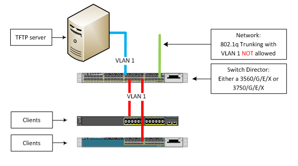
- Network Diagram
- Anything else?
- Gotchas?
- Configuration time!
- How does it look like?
- How long does it take?
- Troubleshooting Section
- WTF Section
- WTF, How-Did-You-Get-This-To-Work Section
- 3560CG-8PC Configuration
- ME-3800X-24FS Configuration
- So all un-supported appliance now supported?
Before we begin, I’ve segmented this document into three subnets. They are:
1) Introduction section 2) Troubleshooting section. 3) WTF section (I’ll explain later).
Introduction
What does this do?
Let’s say that you have a pile of switches you need to deploy soon-ish. Now, your stack will “mostly” have the same configuration except the IP Addresses and Hostname. Let’s say that your switch configurations are composed of two parts: Dynamic (unique information such as IP Addresses) or Static (or fixed information).
Before the advent of Zero-Touch, one would sit down behind the pile switches and configure them one by one, very monotonous and very repetitive.
With Zero-Touch, all one has to do is connect a new switch’s Ethernet or Management Port to the switch “Director” Ethernet port (explained later) using an Ethernet cable. Power up the new switch and once the boot-up process completes the new switch will receive a Static Configuration and an IOS upgrade/downgrade from the Director.
Now, for safety reason, you have to manually configure what kind of switch you want to enable. And when I say “what kind of switch”, I meant SPECIFIC models. This feature will be able to determine if your switch is a 24- or 48-port, whether you switch has 2- or 4- SFP ports, etc. For short, very platform-specific.
Zero-Touch uses VLAN 1 and Cisco Discovery Protocol (CDP). Zero-Touch requires VLAN 1 because a new factory-fresh switch does not have any other VLANs other than VLAN 1. Ok so far?
Zero-Touch also uses CDP to “interrogate” the client switch. Zero-Touch takes the CDP value and pulls the “platform” information to know what kind of appliance wants “in” to the Zero-Touch and whether or not there are settings. Because of this, the director will NOT push the IOS and/or the static configuration to, say a 2960 switch to a 3560 (unless you incorrectly configured it to do so). If it’s not in the list, then the Director will not action.
What appliances are supported?
Table 1 Supported Switches
| Switch | Director | Client |
|---|---|---|
|
Catalyst 3750-X |
Yes | Yes |
|
Catalyst 3750-E |
Yes | Yes |
| Cisco 3750 | Yes | Yes |
|
Cisco 3560-X |
Yes | Yes |
|
Cisco 3560-E |
Yes | Yes |
|
Cisco 3560-C |
No | Yes |
|
Cisco 3560 |
Yes | Yes |
|
Catalyst 2960-S |
No | Yes |
|
Catalyst 2960-C |
No | Yes |
|
Catalyst 2960 |
No | Yes |
|
Catalyst 2975 |
No | Yes |
|
SM-ES2-16-P |
No | Yes |
|
SM-ES3 SKUs |
No | Yes |
|
NME-16ES-1G-P |
No | yes |
|
NM-16-ESW |
Yes | No |
Table 2 Supported Routers
| Router | Director | Client |
|---|---|---|
| Cisco 3900 Series Integrated Services Routers G2 | Yes | No |
| Cisco 2900 Series Integrated Services Routers G2 | Yes | No |
| Cisco 1900 Series Integrated Services Routers G2 | Yes | No |
| Cisco 3800 Series Integrated Services Routers | Yes | No |
| Cisco 2800 Series Integrated Services Routers | Yes | No |
| Cisco 1800 Series Integrated Services Routers | Yes | No |
Note: If your switch appliance (like 3560CG or ME-3800X) is not in this list, boy, do I have a joke for you! Read on!
So what do I need?
No biggie. You need a TFTP server of course. A 3560 or 3750 switch running at least IOS version 12.2(55)SE1 IP Base which will act as a Director. Cisco documentation will state that Zero-Touch SmartPort was introduced starting with IOS 12.2(55)SE but Cisco insiders recommend using the SE1 rebuild because of “improvements” (aka bug fixes).
Network Diagram
That’s simple.
Anything else?
Of course you need the IOS TAR files of the switches involved. You also need to create a few text files. They are:
- config template – The text file is the configuration template for a specific model of switch. Syntax or naming convention would be anything of your choice.
- imagelist - This file contains only one string: The complete IOS filename (example: c2960s-universalk9-tar.122-58.SE1.tar). The naming convention is a wee bit “strange”. The naming convention is based on the built-in group (or profile) when configuring the VStack. For example, for a 2960 LAN Lite the filename is “2960-24-8poe-lanlite-imagelist.txt”. For a 2960S-24PD the filename is called “2960s-24-2sfp-poe-imagelist.txt” and for a 2960S-48LPS the filename is called “2960s-48-4sfp-poe-imagelist.txt”.
Gotchas?
- During the entire process, if you do anything, like hit any keyboard while consoled into the client switch (accidentally) the process will stop (hence the term Zero-Touch).
- VLAN 1 is mandatory. This is because when you get a switch out of the box VLAN 1 is the only VLAN available.
- This feature does NOT like the “/” or “\” symbols. For example, when you are specifying where the IOS image and/or config template file is located it will only accept this form of syntax: tftp://IP Address of TFTP server/IOS file.tar
The syntax of tftp://IP Address of TFTP server/subdirectory/IOS file.tar is going to cause issues and best be avoided. - The three files (IOS TAR file, config template.txt file and imagelist.txt file) must be located in the default folder of the TFTP server.
- If your switch has a Management Port you can use this as well as any switch port.
Configuration time!
It’s simple.
- Interface configuration for the clients AND the TFTP server:
interface GigabitEthernet <BLAH>
description Build LAN
switchport mode access
switchport access VLAN 1 [IMPORTANT]
load-interval 30 [OPTIONAL]
spanning-tree portfast - Enable VLAN 1:
Director# configure terminal
Director(config)# interface vlan 1
Director(config)# no shutdown
Director(config)# ip address 1.1.1.254 255.0.0.0 - Enable SmartInstall on the Director:
Director(config)# vstack director 1.1.1.254
Director(config)# vstack basic - Configure a DHCP scope for client switches:
Note: TFTP server IP address is 1.1.1.1/8 for the sake of the demonstration
Director(config)# vstack dhcp-localserver badda-bing
Director(config)# address-pool 1.1.1.0 255.0.0.0
Director(config)# file-server 1.1.1.1
Director(config)# default-router 1.1.1.254
Connect the link between your Director and the TFTP server into a port configured as VLAN 1. - Configure Built-In Groups (or profiles) and specify the location of the IOS image and the config template file:
Director(config)# vstack group built-in 2960 24-8poe-lanlite
Director(config)# image tftp://1.1.1.1/c2960-lanlitek9-tar.122-58.SE1.tar
Director(config)# config tftp://1.1.1.1/2960lite_config.txt
Optional: What if I want to create a few more of these so-called built-in groups because I have a number of different models, for example, 2960S-24-PLD:
Director(config)# vstack group built-in 2960s 24-2sfp-poe
Director(config)# image tftp://1.1.1.1/c2960s-universalk9-tar.122-58.SE1.tar
Director(config)# config tftp://1.1.1.1/2960s_config.txt - Connect a new switch to the Director port configured as VLAN 1. Make sure the switch does not have any config. If unsure, console into the switch and erase the configuration (wr erase) and reboot (reload).
How does it look like?
Press RETURN to get started!
*Mar 1 00:00:44.048: %LINEPROTO-5-UPDOWN: Line protocol on Interface Vlan1,
changed state to downAuth Manager registration failed
*Mar 1 00:00:45.231: %SPANTREE-5-EXTENDED_SYSID: Extended SysId enabled
for type vlan
*Mar 1 00:01:06.756: %SYS-5-RESTART: System restarted --
Cisco IOS Software, C2960 Software (C2960-LANLITEK9-M), Version 12.2(58)SE1,
RELEASE SOFTWARE (fc1)
Technical Support: http://www.cisco.com/techsupport
Copyright (c) 1986-2011 by Cisco Systems, Inc.
Compiled Thu 05-May-11 02:53 by prod_rel_team
*Mar 1 00:01:13.677: %LINK-3-UPDOWN: Interface GigabitEthernet0/2,
changed state to up
*Mar 1 00:01:14.683: %LINEPROTO-5-UPDOWN: Line protocol on Interface
GigabitEthernet0/2, changed state to up
*Mar 1 00:01:41.703: %LINEPROTO-5-UPDOWN: Line protocol on Interface
Vlan1, changed state to up
!!!! Gets a valid IP Address
*Mar 1 00:01:59.764: AUTOINSTALL: Vlan1 is assigned 1.0.0.9 got vend id
vend spec. info ret: succeed got vend id vend spec. info ret: succeed
!!!! Don’t worry about the word “Aborted” because the “AUTOINSTALL” is part of the feature.
*Mar 1 00:02:20.416: %SMI-6-AUTOINSTALL: Aborted AUTOINSTALL
*Mar 1 00:02:20.416: AUTOINSTALL: Aborted
!!!! Downloads the config template file into the startup-config.
*Mar 1 00:02:20.416: %SMI-6-UPGRD_STARTED: Device (IP address: 1.0.0.9)
startup-config upgrade has started
Loading 2960lite_config.txt from 1.1.1.1 (via Vlan1): !
[OK - 1324 bytes]
*Mar 1 00:02:38.502: %SYS-5-CONFIG_NV_I: Nonvolatile storage configured
from tftp://1.1.1.1/2960lite_config.txt by console
*Mar 1 00:02:39.517: %SMI-6-UPGRD_SUCCESS: Device (IP address: 1.0.0.9)
startup-config has upgraded successfully
*Mar 1 00:02:39.526: %SMI-6-UPGRD_STARTED: Device (IP address: 1.0.0.9)
image upgrade has started
!!!! Next the IOS image list is being verified to know what file is to be used.
Loading 2960-24-8poe-lanlite-imagelist.txt from 1.1.1.1 (via Vlan1): !
[OK - 34 bytes]
!!!! Don’t worry about the “could not buffer”. Happens all the time.
Could not buffer tarfile...using multiple downloads
examining image...
extracting info (107 bytes)
!!!! IOS is being downloaded and extracted to the new switch
System Type: 0x00000000
Ios Image File Size: 0x009DFA00
Total Image File Size: 0x00DC0200
Minimum Dram required: 0x04000000
Image Suffix: lanlitek9-122-58.SE1
Image Directory: c2960-lanlitek9-mz.122-58.SE1
Image Name: c2960-lanlitek9-mz.122-58.SE1.bin
Image Feature: LAYER_2|SSH|3DES|MIN_DRAM_MEG=64
Old image for switch 1: same as image to overwrite
Image to be installed already exists...will be removed before download.
Deleting `flash:c2960-lanlitek9-mz.122-58.SE1' to create required space
Extracting images from archive into flash...
c2960-lanlitek9-mz.122-58.SE1/ (directory)
c2960-lanlitek9-mz.122-58.SE1/html/ (directory)
--- CUT ---
extracting c2960-lanlitek9-mz.122-58.SE1/info (427 bytes)
extracting info (107 bytes)
Installing (renaming): `flash:update/c2960-lanlitek9-mz.122-58.SE1' ->
`flash:/c2960-lanlitek9-mz.122-58.SE1'
New software image installed in flash:/c2960-lanlitek9-mz.122-58.SE1
!!!! Finish
All software images installed.
Requested system reload in progress...
*Mar 1 00:12:16.586: %SYS-5-RELOAD: Reload requested by SMI IBC client process.
Reload Reason: Switch upgraded through Smart Install.
How long does it take?
Depending on the model of your switch between 10 to 15 minutes from the time the “client” is seen by the VStack Director.
Troubleshooting Section
The most useful command I’ve used is the “sh vstack status”.
SmartInstall: ENABLED
Status: Device_type Health_status Join-window_status Upgrade_status
Device_type: S - Smart install N - Non smart install P - Pending
Health_status: A - Active I - Inactive
Join-window_Status: a - Allowed h - On-hold d - Denied
Image Upgrade: i - in progress I - done X - failed
Config Upgrade: c - in progress C - done x - failed
Director Database:
DevNo MAC Address Product-ID IP_addr Hostname Status
===== ============== ================= =============== ========== =========
0 001e.490e.7600 WS-C3750G-24PS 192.168.1.2 Director Director
Pay close attention to the output under the “Status” section. This will tell you the progress of the Zero-Touch based on each “DevNo” or Index Number (first column).
There are two commands that the original Cisco documentation will tell you. They are:
- vstack download-config [tftp://<TFTP IP address> or DevNo] Client_IP_Address PASSWORD startup
This command will tell the Director to manually push the Static configuration to the switch. - vstack download-image [tftp://<TFTP IP address> or DevNo] Client_IP_Address PASSWORD reload
This command will tell the Director to manually push the IOS to the switch and overwrite previous version.
I have a 50% success rate when using these two commands. Let me explain:
The Zero-Touch works great. Most of the time when I run into trouble, the most common issue I would see are is the switch would fail to download the config, download the IOS, reboot and attempt (but fail) to download the config. Sometimes it won’t even download the IOS.
Like I’ve mentioned before the two commands that Cisco recommends on using doesn’t work all the time. I would resort to power down the offending client, count to five, and powering up the client. Now THIS process works for me 100% of the time.
WTF Section
This section is called the WTF section. Why?
Let’s say that you read Table 1 and saw that you have a number of switch models that are NOT in the table, for example a Cisco 3560CG-8PC (in the list but this model is not available in the configuration) or Cisco ME-3800X-24FS. Well, in the back of your mind, you’d probably thinking that if you are reading this section, then something can be done to enable these unsupported models to work with Zero-Touch. Well? Can you?
And the short answer is? YES (if you use the magic word).
WTF, How-Did-You-Get-This-To-Work Section
a) Same rules apply for the Switch Director:
- 3560/G/E/X or 3750/G/E/X;
- Minimum IOS 12.2(55)SE1 or later; and
- VLAN 1 only to the clients and to the TFTP server
- CDP must be enabled.
b) You need the IOS TAR file of the switches
c) You need to create a Static Configuration file per switch; and
d) You need to create an image file
In my case, I had to deploy 3560CG-8PC and ME-3800X-24FS. So my image filename has to be exact. For the 3560CG-8PC has to be exact “3560CG-8PC-imagelist.txt” and the ME-3800 is called “ME3800X-imagelist.txt”.
3560CG-8PC Configuration
Director(config)# vstack group custom <Enter any value> product-id
Director(config)# image tftp://<TFTP IP Address>/<IOS_filename>.TAR
Director(config)# config tftp://<TFTP IP Address>/<Config_filename>.txt
!!!! The magic word is “match”.
Director(config)# match WS-C3560CG-8PC-S
ME-3800X-24FS Configuration
Director(config)# vstack group custom <Enter any value> product-id
Director(config)# image tftp://<TFTP IP Address>/<IOS_filename>.TAR
Director(config)# config tftp://<TFTP IP Address>/<Config_filename>.txt
!!!! The magic word is “match”.
Director(config)# match ME-3800X-24FS-M
The value after the “match” statement is very specific. The value comes out of the client’s Product ID (PID) and must be entered in ALL-CAPS. The Zero-Touch function will not work if this value is expressed in any other mean.
So all un-supported appliance now supported?
Unfortunately, the answer is NO.
I’ve tried using a 2950 and it won’t work. I don’t have the resources to test but if a switch (like the 3550 or the 2970) can run IOS version 12.2 then it could work using the “match” statement.
- Mark as Read
- Mark as New
- Bookmark
- Permalink
- Report Inappropriate Content
Hello,
Can you please help me?
I have 3750 switch and 2960 client. i need to set it up IOS and configuration in client.
I didnt get the txt file [art? what i have to do ?
- Mark as Read
- Mark as New
- Bookmark
- Permalink
- Report Inappropriate Content
I didnt get the txt file [art? what i have to do ?
Open a new thread and post the configuration of your 3750 and the output to the command "sh version".
- Mark as Read
- Mark as New
- Bookmark
- Permalink
- Report Inappropriate Content
I have 3750 as a Director
Hostname: Director
Config t
vstack director 192.168.1.10
vstack basic
vstack dhcp-localsever pool1
address-pool 192.168.1.0 255.255.255.0
default-router 192.168.1.1
file-server 192.168.1.40
exit
ip dhcp remember
end
Configuration for IOS
Config terminal
vstack director 1.1.1.10
vstack basic
vstack image tftp://192.168.1.40/c2960-lanbasek9-mz.150-2.SE8.bin
vstack config tftp://192.168.1.40/c2960-lanbasek9-config.txt (Can I know what this one do ?)
vstack script tftp://192.168.1.40/2960 lanbase_post_install.txt (Is this important to type this command?)
end
Is this good? By doing applying this configuration will upgrade my IOS for client switch?
Thank you
- See more at: https://supportforums.cisco.com/document/12533561/configuration-good-upgrade-ios-2960-switch-3750-switch#sthash.LbCqDclV.dpuf
- Mark as Read
- Mark as New
- Bookmark
- Permalink
- Report Inappropriate Content
I tried but my client switch is not getting anything.
Show version:
director#sh version
Cisco IOS Software, C3750 Software (C3750-IPBASEK9-M), Version 12.2(58)SE2, RELEASE SOFTWARE (fc1)
Technical Support: http://www.cisco.com/techsupport
Copyright (c) 1986-2011 by Cisco Systems, Inc.
Compiled Thu 21-Jul-11 01:53 by prod_rel_team
ROM: Bootstrap program is C3750 boot loader
BOOTLDR: C3750 Boot Loader (C3750-HBOOT-M) Version 12.2(44)SE5, RELEASE SOFTWARE (fc1)
director uptime is 1 hour, 11 minutes
System returned to ROM by power-on
System image file is "flash:c3750-ipbasek9-mz.122-58.SE2.bin"
This product contains cryptographic features and is subject to United
States and local country laws governing import, export, transfer and
use. Delivery of Cisco cryptographic products does not imply
third-party authority to import, export, distribute or use encryption.
Importers, exporters, distributors and users are responsible for
compliance with U.S. and local country laws. By using this product you
agree to comply with applicable laws and regulations. If you are unable
to comply with U.S. and local laws, return this product immediately.
A summary of U.S. laws governing Cisco cryptographic products may be found at:
http://www.cisco.com/wwl/export/crypto/tool/stqrg.html
If you require further assistance please contact us by sending email to
export@cisco.com.
cisco WS-C3750G-24TS-1U (PowerPC405) processor (revision F0) with 131072K bytes of memory.
Processor board ID FOC1328Y6BM
Last reset from power-on
1 Virtual Ethernet interface
28 Gigabit Ethernet interfaces
The password-recovery mechanism is enabled.
512K bytes of flash-simulated non-volatile configuration memory.
Base ethernet MAC Address : 00:26:52:63:FF:00
Motherboard assembly number : 73-10219-07
Power supply part number : 341-0098-02
Motherboard serial number : FOC132920D3
Power supply serial number : AZS132502L7
Model revision number : F0
Motherboard revision number : D0
Model number : WS-C3750G-24TS-S1U
System serial number : FOC1328Y6BM
Top Assembly Part Number : 800-26859-01
Top Assembly Revision Number : E0
Version ID : V03
CLEI Code Number : CNMWS00ARC
Hardware Board Revision Number : 0x09
Switch Ports Model SW Version SW Image
------ ----- ----- ---------- ----------
* 1 28 WS-C3750G-24TS-1U 12.2(58)SE2 C3750-IPBASEK9-M
Show run
director#sh run
Building configuration...
Current configuration : 3495 bytes
!
! Last configuration change at 00:24:53 UTC Mon Mar 1 1993
!
version 12.2
no service pad
service timestamps debug datetime msec
service timestamps log datetime msec
no service password-encryption
!
hostname director
!
boot-start-marker
boot-end-marker
!
!
no aaa new-model
switch 1 provision ws-c3750g-24ts-1u
system mtu routing 1500
!
!
!
!
crypto pki trustpoint TP-self-signed-1382285056
enrollment selfsigned
subject-name cn=IOS-Self-Signed-Certificate-1382285056
revocation-check none
rsakeypair TP-self-signed-1382285056
!
!
crypto pki certificate chain TP-self-signed-1382285056
certificate self-signed 01
3082023E 308201A7 A0030201 02020101 300D0609 2A864886 F70D0101 04050030
31312F30 2D060355 04031326 494F532D 53656C66 2D536967 6E65642D 43657274
69666963 6174652D 31333832 32383530 3536301E 170D3933 30333031 30303032
33385A17 0D323030 31303130 30303030 305A3031 312F302D 06035504 03132649
4F532D53 656C662D 5369676E 65642D43 65727469 66696361 74652D31 33383232
38353035 3630819F 300D0609 2A864886 F70D0101 01050003 818D0030 81890281
810096DD 8C7B29E1 919BA252 CC09EBA8 BD103D11 43B069EE DD1E950B A939B5D8
E5DE1A28 0A443A85 975C4155 1004EC2D DE4942D7 1341607D EAE0098A 278C08CD
E53B720B 8B534FDF 4EBFC33F 0A34BE53 FCE99E57 24740C8B D98C61EB 808EFE71
71B02293 BFB60979 A44A0E60 474F9444 6621A9FD A12FB7E2 C4E58687 38E37080
F4530203 010001A3 66306430 0F060355 1D130101 FF040530 030101FF 30110603
551D1104 0A300882 06537769 74636830 1F060355 1D230418 30168014 2B7FE6A3
C96AC497 0465EAE2 B53EDFB2 CAB864DA 301D0603 551D0E04 1604142B 7FE6A3C9
6AC49704 65EAE2B5 3EDFB2CA B864DA30 0D06092A 864886F7 0D010104 05000381
81008D67 CCE491E7 5A8AA578 74993F8E 3493387D DED36189 9EEC607F 372A9A48
6ABF4F23 9C76BA3F A626B186 E9EC4400 4C1CB627 95566229 FA2A127C 99371D8B
942404FA 236C50BE E8434FCF F3FBC555 A7C4CB08 5C275167 7F722121 2C75B9D3
F946CCB4 B1A109FC 2E258624 83727EBD 50DD3CCD C352ABF1 FC4042C6 40D6C8A1 3416
quit
!
!
!
spanning-tree mode pvst
spanning-tree extend system-id
!
vlan internal allocation policy ascending
!
!
!
!
!
!
interface GigabitEthernet1/0/1
switchport mode access
spanning-tree portfast
!
interface GigabitEthernet1/0/2
!
interface GigabitEthernet1/0/3
!
interface GigabitEthernet1/0/4
!
interface GigabitEthernet1/0/5
!
interface GigabitEthernet1/0/6
!
interface GigabitEthernet1/0/7
!
interface GigabitEthernet1/0/8
!
interface GigabitEthernet1/0/9
!
interface GigabitEthernet1/0/10
!
interface GigabitEthernet1/0/11
!
interface GigabitEthernet1/0/12
!
interface GigabitEthernet1/0/13
!
interface GigabitEthernet1/0/14
!
interface GigabitEthernet1/0/15
!
interface GigabitEthernet1/0/16
!
interface GigabitEthernet1/0/17
!
interface GigabitEthernet1/0/18
!
interface GigabitEthernet1/0/19
!
interface GigabitEthernet1/0/20
!
interface GigabitEthernet1/0/21
!
interface GigabitEthernet1/0/22
!
interface GigabitEthernet1/0/23
!
interface GigabitEthernet1/0/24
!
interface GigabitEthernet1/0/25
!
interface GigabitEthernet1/0/26
!
interface GigabitEthernet1/0/27
!
interface GigabitEthernet1/0/28
!
interface Vlan1
ip address 1.1.1.254 255.0.0.0
!
ip http server
ip http secure-server
!
!
logging esm config
tftp-server client_cfg.txt
vstack config tftp://1.1.1.1/2960s_config.txt
!
!
vstack dhcp-localserver smart_install
address-pool 1.1.1.0 255.0.0.0
file-server 1.1.1.1
default-router 1.1.1.254
!
vstack director 1.1.1.254
vstack basic
!
line con 0
line vty 0 4
login
line vty 5 15
login
!
end
- Mark as Read
- Mark as New
- Bookmark
- Permalink
- Report Inappropriate Content
vstack config tftp://1.1.1.1/2960s_config.txt
!
vstack dhcp-localserver smart_install
 address-pool 1.1.1.0 255.0.0.0
 file-server 1.1.1.1
 default-router 1.1.1.254
!
vstack director 1.1.1.254
vstack basic
Configuration is missing the vstack built-in group.
- Mark as Read
- Mark as New
- Bookmark
- Permalink
- Report Inappropriate Content
Thank you very much
I have a question about vlans
After the smart small configuration I saw that my client is not taking vlan 100 and vlan 150. Although I put in my config file these two vlans, Can I know why?
Or smart install will not support other than vlan 1 ?
- Mark as Read
- Mark as New
- Bookmark
- Permalink
- Report Inappropriate Content
Or smart install will not support other than vlan 1 ?
Depends on the IOS. Newer IOS will support the command "vstack startup vlan" and enable other VLANs other than VLAN 1.
- Mark as Read
- Mark as New
- Bookmark
- Permalink
- Report Inappropriate Content
I am using 3750G 12.2(58) in a director. and my client is 2960 8.
Can you please tell me the commands for vlans, what command will work in a director to config vlan 200, 100, and 150 in my client switch.
Thank you very much for your help.
- Mark as Read
- Mark as New
- Bookmark
- Permalink
- Report Inappropriate Content
I am using 3750G 12.2(58)
Can you please tell me the commands for vlans,
The command "vstack startup-vlan" only appears in 15.0(2)SE.
- Mark as Read
- Mark as New
- Bookmark
- Permalink
- Report Inappropriate Content
So if I have 6 vlans
the command will be like that in the director
vstack startup-vlan 200
vstack startup-vlan100
vstack startup-vlan150 ???
and there will no vlan 1 ?? like interface vlan 1
no shutdown ??
and I also have to configure vlan in my config file too right?
- Mark as Read
- Mark as New
- Bookmark
- Permalink
- Report Inappropriate Content
Only 1 VLAN will work.
Why would anyone have more than one VStack VLAN in the first place??
- Mark as Read
- Mark as New
- Bookmark
- Permalink
- Report Inappropriate Content
I am sorry, I think you didn't get the question
I am explaining again.
Here is my Client Configuration file
Enable
config terminal
Hostname Client
enable secret cisco1
line console 0
password cisco1
login
logging synchronous
exec-timeout 30 0
exit
vlan 200
name test
exit
vlan 204
name sam
exit
vlan 20
name guest
exit
interface fa0/2
switchport access vlan 200
switchport mode access
interface fa0/4
switchport access vlan 204
switchport mode access
interface fa0/2
switchport access vlan 20
switchport mode access
After the smart install this config file and IOS is taking
but when I am doing show vlan in my client switch, Client switch is not showing all this vlans which is in my config file.
My Client switch is taking all configuration expect vlans
Can you tell why is like this?
- Mark as Read
- Mark as New
- Bookmark
- Permalink
- Report Inappropriate Content
Configure VTP mode to Transparent.
- Mark as Read
- Mark as New
- Bookmark
- Permalink
- Report Inappropriate Content
Hello Leo,
Thank you very much for your reply, If I don't have switches in my location. Actually its in different location and we don't have technical person in that location. Is there any other way to do that without touching my client switch??
Thank you
- Mark as Read
- Mark as New
- Bookmark
- Permalink
- Report Inappropriate Content
Remote into the switch and enable VTP mode Transparent.
Find answers to your questions by entering keywords or phrases in the Search bar above. New here? Use these resources to familiarize yourself with the community: