- Cisco Community
- Technology and Support
- Networking
- Networking Knowledge Base
- How to use Zero-Touch SmartInstall
- Subscribe to RSS Feed
- Mark as New
- Mark as Read
- Bookmark
- Subscribe
- Printer Friendly Page
- Report Inappropriate Content
- Subscribe to RSS Feed
- Mark as New
- Mark as Read
- Bookmark
- Subscribe
- Printer Friendly Page
- Report Inappropriate Content
07-05-2012 08:26 PM - edited 03-01-2019 04:49 PM
- Introduction
- What does this do?
- What appliances are supported?
- So what do I need?
- Network Diagram
- Anything else?
- Gotchas?
- Configuration time!
- How does it look like?
- How long does it take?
- Troubleshooting Section
- WTF Section
- WTF, How-Did-You-Get-This-To-Work Section
- 3560CG-8PC Configuration
- ME-3800X-24FS Configuration
- So all un-supported appliance now supported?
Before we begin, I’ve segmented this document into three subnets. They are:
1) Introduction section 2) Troubleshooting section. 3) WTF section (I’ll explain later).
Introduction
What does this do?
Let’s say that you have a pile of switches you need to deploy soon-ish. Now, your stack will “mostly” have the same configuration except the IP Addresses and Hostname. Let’s say that your switch configurations are composed of two parts: Dynamic (unique information such as IP Addresses) or Static (or fixed information).
Before the advent of Zero-Touch, one would sit down behind the pile switches and configure them one by one, very monotonous and very repetitive.
With Zero-Touch, all one has to do is connect a new switch’s Ethernet or Management Port to the switch “Director” Ethernet port (explained later) using an Ethernet cable. Power up the new switch and once the boot-up process completes the new switch will receive a Static Configuration and an IOS upgrade/downgrade from the Director.
Now, for safety reason, you have to manually configure what kind of switch you want to enable. And when I say “what kind of switch”, I meant SPECIFIC models. This feature will be able to determine if your switch is a 24- or 48-port, whether you switch has 2- or 4- SFP ports, etc. For short, very platform-specific.
Zero-Touch uses VLAN 1 and Cisco Discovery Protocol (CDP). Zero-Touch requires VLAN 1 because a new factory-fresh switch does not have any other VLANs other than VLAN 1. Ok so far?
Zero-Touch also uses CDP to “interrogate” the client switch. Zero-Touch takes the CDP value and pulls the “platform” information to know what kind of appliance wants “in” to the Zero-Touch and whether or not there are settings. Because of this, the director will NOT push the IOS and/or the static configuration to, say a 2960 switch to a 3560 (unless you incorrectly configured it to do so). If it’s not in the list, then the Director will not action.
What appliances are supported?
Table 1 Supported Switches
| Switch | Director | Client |
|---|---|---|
|
Catalyst 3750-X |
Yes | Yes |
|
Catalyst 3750-E |
Yes | Yes |
| Cisco 3750 | Yes | Yes |
|
Cisco 3560-X |
Yes | Yes |
|
Cisco 3560-E |
Yes | Yes |
|
Cisco 3560-C |
No | Yes |
|
Cisco 3560 |
Yes | Yes |
|
Catalyst 2960-S |
No | Yes |
|
Catalyst 2960-C |
No | Yes |
|
Catalyst 2960 |
No | Yes |
|
Catalyst 2975 |
No | Yes |
|
SM-ES2-16-P |
No | Yes |
|
SM-ES3 SKUs |
No | Yes |
|
NME-16ES-1G-P |
No | yes |
|
NM-16-ESW |
Yes | No |
Table 2 Supported Routers
| Router | Director | Client |
|---|---|---|
| Cisco 3900 Series Integrated Services Routers G2 | Yes | No |
| Cisco 2900 Series Integrated Services Routers G2 | Yes | No |
| Cisco 1900 Series Integrated Services Routers G2 | Yes | No |
| Cisco 3800 Series Integrated Services Routers | Yes | No |
| Cisco 2800 Series Integrated Services Routers | Yes | No |
| Cisco 1800 Series Integrated Services Routers | Yes | No |
Note: If your switch appliance (like 3560CG or ME-3800X) is not in this list, boy, do I have a joke for you! Read on!
So what do I need?
No biggie. You need a TFTP server of course. A 3560 or 3750 switch running at least IOS version 12.2(55)SE1 IP Base which will act as a Director. Cisco documentation will state that Zero-Touch SmartPort was introduced starting with IOS 12.2(55)SE but Cisco insiders recommend using the SE1 rebuild because of “improvements” (aka bug fixes).
Network Diagram
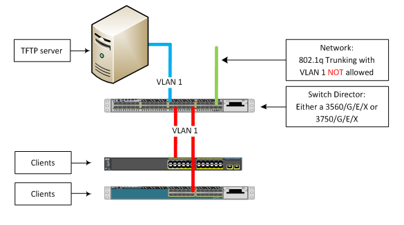
That’s simple.
Anything else?
Of course you need the IOS TAR files of the switches involved. You also need to create a few text files. They are:
- config template – The text file is the configuration template for a specific model of switch. Syntax or naming convention would be anything of your choice.
- imagelist - This file contains only one string: The complete IOS filename (example: c2960s-universalk9-tar.122-58.SE1.tar). The naming convention is a wee bit “strange”. The naming convention is based on the built-in group (or profile) when configuring the VStack. For example, for a 2960 LAN Lite the filename is “2960-24-8poe-lanlite-imagelist.txt”. For a 2960S-24PD the filename is called “2960s-24-2sfp-poe-imagelist.txt” and for a 2960S-48LPS the filename is called “2960s-48-4sfp-poe-imagelist.txt”.
Gotchas?
- During the entire process, if you do anything, like hit any keyboard while consoled into the client switch (accidentally) the process will stop (hence the term Zero-Touch).
- VLAN 1 is mandatory. This is because when you get a switch out of the box VLAN 1 is the only VLAN available.
- This feature does NOT like the “/” or “\” symbols. For example, when you are specifying where the IOS image and/or config template file is located it will only accept this form of syntax: tftp://IP Address of TFTP server/IOS file.tar
The syntax of tftp://IP Address of TFTP server/subdirectory/IOS file.tar is going to cause issues and best be avoided. - The three files (IOS TAR file, config template.txt file and imagelist.txt file) must be located in the default folder of the TFTP server.
- If your switch has a Management Port you can use this as well as any switch port.
Configuration time!
It’s simple.
- Interface configuration for the clients AND the TFTP server:
interface GigabitEthernet <BLAH>
description Build LAN
switchport mode access
switchport access VLAN 1 [IMPORTANT]
load-interval 30 [OPTIONAL]
spanning-tree portfast - Enable VLAN 1:
Director# configure terminal
Director(config)# interface vlan 1
Director(config)# no shutdown
Director(config)# ip address 1.1.1.254 255.0.0.0 - Enable SmartInstall on the Director:
Director(config)# vstack director 1.1.1.254
Director(config)# vstack basic - Configure a DHCP scope for client switches:
Note: TFTP server IP address is 1.1.1.1/8 for the sake of the demonstration
Director(config)# vstack dhcp-localserver badda-bing
Director(config)# address-pool 1.1.1.0 255.0.0.0
Director(config)# file-server 1.1.1.1
Director(config)# default-router 1.1.1.254
Connect the link between your Director and the TFTP server into a port configured as VLAN 1. - Configure Built-In Groups (or profiles) and specify the location of the IOS image and the config template file:
Director(config)# vstack group built-in 2960 24-8poe-lanlite
Director(config)# image tftp://1.1.1.1/c2960-lanlitek9-tar.122-58.SE1.tar
Director(config)# config tftp://1.1.1.1/2960lite_config.txt
Optional: What if I want to create a few more of these so-called built-in groups because I have a number of different models, for example, 2960S-24-PLD:
Director(config)# vstack group built-in 2960s 24-2sfp-poe
Director(config)# image tftp://1.1.1.1/c2960s-universalk9-tar.122-58.SE1.tar
Director(config)# config tftp://1.1.1.1/2960s_config.txt - Connect a new switch to the Director port configured as VLAN 1. Make sure the switch does not have any config. If unsure, console into the switch and erase the configuration (wr erase) and reboot (reload).
How does it look like?
Press RETURN to get started!
*Mar 1 00:00:44.048: %LINEPROTO-5-UPDOWN: Line protocol on Interface Vlan1,
changed state to downAuth Manager registration failed
*Mar 1 00:00:45.231: %SPANTREE-5-EXTENDED_SYSID: Extended SysId enabled
for type vlan
*Mar 1 00:01:06.756: %SYS-5-RESTART: System restarted --
Cisco IOS Software, C2960 Software (C2960-LANLITEK9-M), Version 12.2(58)SE1,
RELEASE SOFTWARE (fc1)
Technical Support: http://www.cisco.com/techsupport
Copyright (c) 1986-2011 by Cisco Systems, Inc.
Compiled Thu 05-May-11 02:53 by prod_rel_team
*Mar 1 00:01:13.677: %LINK-3-UPDOWN: Interface GigabitEthernet0/2,
changed state to up
*Mar 1 00:01:14.683: %LINEPROTO-5-UPDOWN: Line protocol on Interface
GigabitEthernet0/2, changed state to up
*Mar 1 00:01:41.703: %LINEPROTO-5-UPDOWN: Line protocol on Interface
Vlan1, changed state to up
!!!! Gets a valid IP Address
*Mar 1 00:01:59.764: AUTOINSTALL: Vlan1 is assigned 1.0.0.9 got vend id
vend spec. info ret: succeed got vend id vend spec. info ret: succeed
!!!! Don’t worry about the word “Aborted” because the “AUTOINSTALL” is part of the feature.
*Mar 1 00:02:20.416: %SMI-6-AUTOINSTALL: Aborted AUTOINSTALL
*Mar 1 00:02:20.416: AUTOINSTALL: Aborted
!!!! Downloads the config template file into the startup-config.
*Mar 1 00:02:20.416: %SMI-6-UPGRD_STARTED: Device (IP address: 1.0.0.9)
startup-config upgrade has started
Loading 2960lite_config.txt from 1.1.1.1 (via Vlan1): !
[OK - 1324 bytes]
*Mar 1 00:02:38.502: %SYS-5-CONFIG_NV_I: Nonvolatile storage configured
from tftp://1.1.1.1/2960lite_config.txt by console
*Mar 1 00:02:39.517: %SMI-6-UPGRD_SUCCESS: Device (IP address: 1.0.0.9)
startup-config has upgraded successfully
*Mar 1 00:02:39.526: %SMI-6-UPGRD_STARTED: Device (IP address: 1.0.0.9)
image upgrade has started
!!!! Next the IOS image list is being verified to know what file is to be used.
Loading 2960-24-8poe-lanlite-imagelist.txt from 1.1.1.1 (via Vlan1): !
[OK - 34 bytes]
!!!! Don’t worry about the “could not buffer”. Happens all the time.
Could not buffer tarfile...using multiple downloads
examining image...
extracting info (107 bytes)
!!!! IOS is being downloaded and extracted to the new switch
System Type: 0x00000000
Ios Image File Size: 0x009DFA00
Total Image File Size: 0x00DC0200
Minimum Dram required: 0x04000000
Image Suffix: lanlitek9-122-58.SE1
Image Directory: c2960-lanlitek9-mz.122-58.SE1
Image Name: c2960-lanlitek9-mz.122-58.SE1.bin
Image Feature: LAYER_2|SSH|3DES|MIN_DRAM_MEG=64
Old image for switch 1: same as image to overwrite
Image to be installed already exists...will be removed before download.
Deleting `flash:c2960-lanlitek9-mz.122-58.SE1' to create required space
Extracting images from archive into flash...
c2960-lanlitek9-mz.122-58.SE1/ (directory)
c2960-lanlitek9-mz.122-58.SE1/html/ (directory)
--- CUT ---
extracting c2960-lanlitek9-mz.122-58.SE1/info (427 bytes)
extracting info (107 bytes)
Installing (renaming): `flash:update/c2960-lanlitek9-mz.122-58.SE1' ->
`flash:/c2960-lanlitek9-mz.122-58.SE1'
New software image installed in flash:/c2960-lanlitek9-mz.122-58.SE1
!!!! Finish
All software images installed.
Requested system reload in progress...
*Mar 1 00:12:16.586: %SYS-5-RELOAD: Reload requested by SMI IBC client process.
Reload Reason: Switch upgraded through Smart Install.
How long does it take?
Depending on the model of your switch between 10 to 15 minutes from the time the “client” is seen by the VStack Director.
Troubleshooting Section
The most useful command I’ve used is the “sh vstack status”.
SmartInstall: ENABLED
Status: Device_type Health_status Join-window_status Upgrade_status
Device_type: S - Smart install N - Non smart install P - Pending
Health_status: A - Active I - Inactive
Join-window_Status: a - Allowed h - On-hold d - Denied
Image Upgrade: i - in progress I - done X - failed
Config Upgrade: c - in progress C - done x - failed
Director Database:
DevNo MAC Address Product-ID IP_addr Hostname Status
===== ============== ================= =============== ========== =========
0 001e.490e.7600 WS-C3750G-24PS 192.168.1.2 Director Director
Pay close attention to the output under the “Status” section. This will tell you the progress of the Zero-Touch based on each “DevNo” or Index Number (first column).
There are two commands that the original Cisco documentation will tell you. They are:
- vstack download-config [tftp://<TFTP IP address> or DevNo] Client_IP_Address PASSWORD startup
This command will tell the Director to manually push the Static configuration to the switch. - vstack download-image [tftp://<TFTP IP address> or DevNo] Client_IP_Address PASSWORD reload
This command will tell the Director to manually push the IOS to the switch and overwrite previous version.
I have a 50% success rate when using these two commands. Let me explain:
The Zero-Touch works great. Most of the time when I run into trouble, the most common issue I would see are is the switch would fail to download the config, download the IOS, reboot and attempt (but fail) to download the config. Sometimes it won’t even download the IOS.
Like I’ve mentioned before the two commands that Cisco recommends on using doesn’t work all the time. I would resort to power down the offending client, count to five, and powering up the client. Now THIS process works for me 100% of the time.
WTF Section
This section is called the WTF section. Why?
Let’s say that you read Table 1 and saw that you have a number of switch models that are NOT in the table, for example a Cisco 3560CG-8PC (in the list but this model is not available in the configuration) or Cisco ME-3800X-24FS. Well, in the back of your mind, you’d probably thinking that if you are reading this section, then something can be done to enable these unsupported models to work with Zero-Touch. Well? Can you?
And the short answer is? YES (if you use the magic word).
WTF, How-Did-You-Get-This-To-Work Section
a) Same rules apply for the Switch Director:
- 3560/G/E/X or 3750/G/E/X;
- Minimum IOS 12.2(55)SE1 or later; and
- VLAN 1 only to the clients and to the TFTP server
- CDP must be enabled.
b) You need the IOS TAR file of the switches
c) You need to create a Static Configuration file per switch; and
d) You need to create an image file
In my case, I had to deploy 3560CG-8PC and ME-3800X-24FS. So my image filename has to be exact. For the 3560CG-8PC has to be exact “3560CG-8PC-imagelist.txt” and the ME-3800 is called “ME3800X-imagelist.txt”.
3560CG-8PC Configuration
Director(config)# vstack group custom <Enter any value> product-id
Director(config)# image tftp://<TFTP IP Address>/<IOS_filename>.TAR
Director(config)# config tftp://<TFTP IP Address>/<Config_filename>.txt
!!!! The magic word is “match”.
Director(config)# match WS-C3560CG-8PC-S
ME-3800X-24FS Configuration
Director(config)# vstack group custom <Enter any value> product-id
Director(config)# image tftp://<TFTP IP Address>/<IOS_filename>.TAR
Director(config)# config tftp://<TFTP IP Address>/<Config_filename>.txt
!!!! The magic word is “match”.
Director(config)# match ME-3800X-24FS-M
The value after the “match” statement is very specific. The value comes out of the client’s Product ID (PID) and must be entered in ALL-CAPS. The Zero-Touch function will not work if this value is expressed in any other mean.
So all un-supported appliance now supported?
Unfortunately, the answer is NO.
I’ve tried using a 2950 and it won’t work. I don’t have the resources to test but if a switch (like the 3550 or the 2970) can run IOS version 12.2 then it could work using the “match” statement.
- Mark as Read
- Mark as New
- Bookmark
- Permalink
- Report Inappropriate Content
Hello Leo,
We are not using VTP in our organization. and I don't want to effect our company environment by enable VTP in each of the switches. Can you please tell me other way to enable Vlans in a client?
Thank you again
")

- Mark as Read
- Mark as New
- Bookmark
- Permalink
- Report Inappropriate Content
we want to use cisco smart install feature to make a rollout process of around 140 easier, thus we wrote a little python based config generator to create the config files, rename them appropriately, upload them to external TFTP server and configure custom group entries on the director switch to match the unique MAC address as reference for each switch, so every switch gets his own personal generated config file.
We're using Version 03.06.03E on the director switch and want to upgrade the client switches to 03.03.05.SE.150-1.EZ5.
we then want to run a post install script to add a SNMP User + create crypto keys.
The image and the startup config upgrade works fine but the client never runs the post_install script, it does not even try to download it from the tftp server!
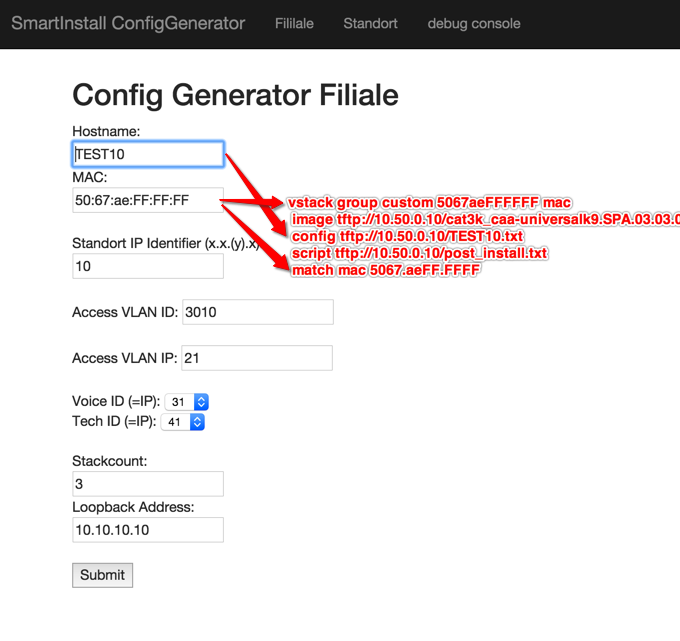
here is what the script configures on the director:
!
vstack group custom 5067aeFFFFFF mac
image tftp://10.50.0.10/cat3k_caa-universalk9.SPA.03.03.05.SE.150-1.EZ5.bin
config tftp://10.50.0.10/TEST10.txt
script tftp://10.50.0.10/post_install.txt
match mac 5067.aeFF.FFFF
!
vstack group custom 80e86fFFFFFF mac
image tftp://10.50.0.10/cat3k_caa-universalk9.SPA.03.03.05.SE.150-1.EZ5.bin
config tftp://10.50.0.10/TEST11.txt
script tftp://10.50.0.10/post_install.txt
match mac 80e8.6fFF.FFFF
!
!
the rest of the director config is straight forward:
!
vstack dhcp-localserver POOL
address-pool 10.50.0.0 255.255.255.0
file-server 10.50.0.10
default-router 10.50.0.1
!
vstack director 10.50.0.5
vstack basic
vstack startup-vlan 1
no vstack backup
DIRECTOR#show vstack do
DIRECTOR#show vstack download-status
SmartInstall: ENABLED
Total no of entries : 2
No client-IP client-MAC Method Image-status Config-status Script-status
=== =============== ============== ============== ============ ============= =============
1 10.50.0.22 80e8.6fFF.FFFF zero-touch UPGRADED UPGRADED NOT STARTED
2 10.50.0.23 5067.aeFF.FFFF zero-touch UPGRADED UPGRADED NOT STARTED
DIRECTOR#
DIRECTOR#
The post install script contains:
“snmp-server user ........cut....”
“crypto key generate.....cut...”
there is not much documentation about post_install scripts. it's been introduced with 3.6.x on the director. I suspect that the client also must run at least 3.6.x+ to support the command.. can someone confirm?
- Mark as Read
- Mark as New
- Bookmark
- Permalink
- Report Inappropriate Content
The image and the startup config upgrade works fine but the client never runs the post_install script, it does not even try to download it from the tftp server!
I don't use the post-install script so I can't comment. Can I ask if you can run a debug?
")
")
- Mark as Read
- Mark as New
- Bookmark
- Permalink
- Report Inappropriate Content
Hi Leo,
thanks for your work on this, really helped me to get basic things up and running initially.
Maybe you can help me with this one...any input would be appreciated...
https://supportforums.cisco.com/discussion/12724921/smart-install-question-post-installfinalizing-tasksran-out-ideastuck
Just posted the link to my initial discussion i created...
Many thanks in advance,
Andreas
- Mark as Read
- Mark as New
- Bookmark
- Permalink
- Report Inappropriate Content
Hi,
This explains for one switch or one stack of switches , how would I use second switch or stack config file?
- Mark as Read
- Mark as New
- Bookmark
- Permalink
- Report Inappropriate Content
Ok, let's say you're trying to prepare a stack (or a number of) switches. The configuration will only go with the stack master, right?
Let all the stack master get the IOS upgraded and download the config. For the stack members, just let them get the IOS upgraded. The config is not required.
In our case, all non-PoE switches are not going to be stack masters so our ZeroTouch only has instructions for the non-PoE switches to upgrade their IOS and no configuration is downloaded.
Does this help?
- Mark as Read
- Mark as New
- Bookmark
- Permalink
- Report Inappropriate Content
Thanks Leo for prompt reply.
My question was getting config file to switches.
As in our configuration we have config template for MDF switch. So if I want to configure IDF's using Smart Install how would I do that?
Once MDF gets it new IOS and MDF-Config.txt file and when I connect IDF do I have to add another line for IDF-Config.txt ?
vstack vlan 1
!
vstack group built-in 2960x 48-4sfp-poe
image tftp://ip add/c2960x-universalk9-tar.152-4.E.tar
config tftp://ip add/MDF-Configtxt
!
!
vstack dhcp-localserver ZERO-TOUCH
address-pool 10.xxx.249.0 255.255.255.0
file-server ip add
default-router ip add
!
vstack director ip add
vstack basic
vstack startup-vlan 1
- Mark as Read
- Mark as New
- Bookmark
- Permalink
- Report Inappropriate Content
Once MDF gets it new IOS and MDF-Config.txt file and when I connect IDF do I have to add another line for IDF-Config.txt ?
How different is the config for the MDF and IDF switches? In my deployment, all our configuration are the same. The only difference is all our 48-port non-PoE will upgrade the IOS. All our 48-port non-PoE switches will never be the configured as the stack master so it doesn't need to download the config file.
If the MDF and IDF config are vastly different, then it's best to change the line "config tftp://10.121.100.194/MDF-Configtxt" when preparing MDF or IDF switches.
- Mark as Read
- Mark as New
- Bookmark
- Permalink
- Report Inappropriate Content
Hi, How do we know if switch (client) got new IOS and config file?
I have wiring vendor that goes onsite to install new switches and they do not have laptop to log in or do ping.
Thanks in advance.
- « Previous
- Next »
Find answers to your questions by entering keywords or phrases in the Search bar above. New here? Use these resources to familiarize yourself with the community: