- Cisco Community
- Technology and Support
- Networking
- Networking Knowledge Base
- MPLS and Traceroute
- Subscribe to RSS Feed
- Mark as New
- Mark as Read
- Bookmark
- Subscribe
- Printer Friendly Page
- Report Inappropriate Content
- Subscribe to RSS Feed
- Mark as New
- Mark as Read
- Bookmark
- Subscribe
- Printer Friendly Page
- Report Inappropriate Content
02-07-2017 06:15 AM - edited 03-01-2019 05:08 PM
This document explains how traceroute works differently in an MPLS Core compared to normal IP-based routing. First, a quick recap on how a UDP traceroute is performed in an IP network.
- The source sends the first UDP probe to the destination with a TTL value of 1
- The first router in transit to the destination responds to the source with a “TTL Exceeded” message.
- The “TTL Exceeded” message is received by the source. The source records the source address of the “TTL Exceeded message”. This is when you see the transit router’s IP address in the traceroute output.
- The “TTL exceeded” message triggers the source to send a second probe with a TTL value of 2.
- This process continues till the probe hits the destination.
- The destination device sends back an ICMP port unreachable message to the source, hence completing the entire traceroute transaction.
The routers in transit perform an IP lookup in their routing table. This makes it possible for them to send a “TTL Exceeded” message back to the source using destination-based IP routing. When a traceroute is performed from one device to another, the transit routers in between need to have the source/destination prefixes in their routing table.
In an MPLS core, the Intermediate routers (LSRs or P routers) do not have the prefixes of the customer routes. The only routers with this information are the PE routers that connect to the customer edge. This means when a traceroute is performed between CE routers over an MPLS infrastructure, the P routers in the MPLS core will not be able to respond with a “TTL Exceeded” message in response to a traceroute probe.
However, that’s not the case.
Consider the topology below. The two CE routers, CE-1 and CE-2 are each located at a remote site and connect to each other over MPLS.

The MPLS core consists of the ingress LSR, PE-1 (from the perspective of CE-1) and the egress LSR, PE-2. P1 and P2 are the intermediate routers that do not run BGP. This means they do not have information about the customer prefixes 5.5.5.5 and 6.6.6.6. Traffic in MPLS core is forwarded based on labels, label-switched, not based on IP lookups.
A trace is sourced from the loopback 5.5.5.5 on CE-1 destined to 6.6.6.6 on CE-2. In the output, we can see hops 2 (12.1.1.2) and 3 (23.1.1.3) show the P routers to be in the path.
CE-1#trace 6.6.6.6 source 5.5.5.5 probe 1
Type escape sequence to abort.
Tracing the route to 6.6.6.6
VRF info: (vrf in name/id, vrf out name/id)
1 15.1.1.1 12 msec
2 12.1.1.2 [MPLS: Labels 201/403 Exp 0] 84 msec
3 23.1.1.3 [MPLS: Labels 300/403 Exp 0] 92 msec
4 46.1.1.4 [MPLS: Label 403 Exp 0] 48 msec
5 46.1.1.6 92 msec
How are the P routers able to respond with a “TTL Exceeded” message to CE-1 if they do not have a route back to CE-1.
In an MPLS Core, the Intermediate LSRs (P) Routers must follow a special procedure to complete the traceroute operation. The first hop (CE-1 to PE-1) uses normal IP destination-based forwarding to return the ICMP TTL Exceeded message. The following is what happens when PE-1 receives the second UDP Probe:
- PE-1 decrements the TTL to 1, creates the label stack, and imposes the VPN and Transport labels accordingly to forward the packet towards P1. The TTL value of 1 is copied to the labels in the label stack.
- P1 receives the Labeled packet from PE-1 and decrements the TTL of the labels
- The TTL reaches 0 and P1 must send an ICMP “TTL Exceeded” message.
- P1 generates a “TTL Exceeded” message, copying the source from the original packet to the destination and using its own incoming interface as the source.
- P1 cannot send the ICMP message back to the originator. Instead, to forward the packet, P1 creates a label stack and imposes the proper remote label from its LFIB that corresponds to the probe’s received label to forward along the original LSP towards PE-2.
- The TTL Exceeded label switched packet is received by P2. P2 pops the top label and forwards the packet to PE-2.
- PE-2 receives the packet and checks its label binding for the VPN label forwarding to CE-2 unlabeled.
- CE-2 performs a routing lookup on the ICMP packet and routes it back towards PE-2.
- PE-2 creates a new Label Stack and forwards the ICMP packet back through the MPLS Core towards CE-1
At the first step, PE-1 performs the normal IP routing housekeeping. It receives a second probe from the originator of the trace with a TTL value of 2 as seen below.
PE-1 consults its routing table and determines the exit interface for the next-hop 4.4.4.4 is a labeled interface, F2/0. PE-1 then consults its LFIB to determine the proper outgoing label needed to reach the next-hop 4.4.4.4 (PE-2). This process is called IP-to-label forwarding because the ingress LSR receives an IP packet that needs to be forwarded as a labeled packet and sent over a specific LSP.
PE-1#show ip route vrf A
----omitted----
6.0.0.0/32 is subnetted, 1 subnets
B 6.6.6.6 [200/156160] via 4.4.4.4, 01:38:11
PE-1#show mpls forwarding-table
Local Outgoing Prefix Bytes Label Outgoing Next Hop
Label Label or Tunnel Id Switched interface
101 201 4.4.4.4/32 0 Fa2/0 12.1.1.2
In an MPLS core, when an LSR receives an IP packet, it decrements the TTL value from the IP header by one (2-1) and copies the new value to all the labels that need to be imposed onto the label stack.

The capture above shows that PE-1 has imposed a VPN label (Label: 403) on top of the original IP packet followed by a Transport Label (Label: 201). In the MPLS Core, the packet will be switched based on the Transport Label. As per the LFIB on PE-1, IP packets that use 4.4.4.4 as next hop should have the outgoing label 201 and exit interface Fa2/0.
PE-1#show mpls forwarding-table
Local Outgoing Prefix Bytes Label Outgoing Next Hop
Label Label or Tunnel Id Switched interface
101 201 4.4.4.4/32 0 Fa2/0 12.1.1.2
102 200 34.1.1.0/24 0 Fa2/0 12.1.1.2
103 Pop Label 23.1.1.0/24 0 Fa2/0 12.1.1.2
104 No Label 5.5.5.5/32[V] 0 Fa0/0 15.1.1.5
105 No Label 15.1.1.0/24[V] 0 aggregate/A
P1 receives the labeled probe packet. P1 needs to forward this as a labeled packet towards the next intermediate LSR, P2. When P1 receives the labeled packet at step 2, it decrements the TTL in the top label of the label stack. In this case, when the TTL in the top label reaches zero:
- The LSR strips off the label stack
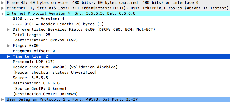
- Examines the underlying IP payload, creates an ICMP “TTL Exceeded” message with the source as the incoming interface, 12.1.1.2, and destination 5.5.5.5, the originator of the traceroute. The TTL value in the IP header is set to 255.
As an intermediate LSR, P1 does not have a route to the originator of the trace 5.5.5.5/32. This leaves P1 with two options when dealing with ICMP messages:
- Drop the packet without generating an ICMP message
- Forward the ICMP message along the LSP to the egress LSR that will have sufficient routing information to deliver the packet.
Cisco’s implementation of MPLS follows the second option. P1, instead of dropping the packet, will copy the original VPN label and consult its LFIB to determine the transport label. The original packet arrived with label 201. In the LFIB, when P1 receives a packet with label 201, the top label should be swapped with 300 and forwarded out its Fa3/0 interface.
P1#show mpls forwarding-table
Local Outgoing Prefix Bytes Label Outgoing Next Hop
Label Label or Tunnel Id Switched interface
200 Pop Label 34.1.1.0/24 0 Fa3/0 23.1.1.3
201 300 4.4.4.4/32 10259 Fa3/0 23.1.1.3
202 Pop Label 1.1.1.1/32 9181 Fa1/0 12.1.1.1
P1 adds label 300 in front of the IP header which has the ICMP “TTL Exceeded” messages as the payload. Since this is a new packet, the TTL value 255 is copied from the new IP header to the newly imposed labels. The packet is now forwarded as per the LFIB above, out F3/0 interface, towards the next intermediate LSR, P2.

At Step 6, P2 receives the labeled packet from P1 that has the incoming label value of 300. It performs a lookup in its LFIB.
P2#show mpls forwarding-table
Local Outgoing Prefix Bytes Label Outgoing Next Hop
Label Label or Tunnel Id Switched interface
300 Pop Label 4.4.4.4/32 8196 Fa4/0 34.1.1.4
301 Pop Label 12.1.1.0/24 0 Fa2/0 23.1.1.2
302 200 1.1.1.1/32 8814 Fa2/0 23.1.1.2
The LFIB on P2 indicates “pop label” for the packets with the incoming label of 300. This means P2 performs PHP by removing the transport label, leaving the VPN label intact. P2 decrements the TTL of the VPN label to 254.
In the next step, the egress LSR, PE-2 receives the VPN-labeled packet from P2 with an incoming label value of 403. As per the LFIB on PE-2, the outgoing label for this packet shows “no label”. This means the egress LSR will not perform an IP lookup, and directly forward this packet towards CE-2.

PE-2#show mpls forwarding-table
Local Outgoing Prefix Bytes Label Outgoing Next Hop
Label Label or Tunnel Id Switched interface
400 301 12.1.1.0/24 0 Fa3/0 34.1.1.3
401 Pop Label 23.1.1.0/24 0 Fa3/0 34.1.1.3
402 302 1.1.1.1/32 0 Fa3/0 34.1.1.3
403 No Label 6.6.6.6/32[V] 4140 Fa0/0 46.1.1.6
404 No Label 46.1.1.0/24[V] 0 aggregate/A
CE-2 receives the ICMP packet in Step 8. It performs an IP lookup for the destination 5.5.5.5 (the destination of the ICMP packet created by P1) and as a result CE-2 forwards the packet back to PE-2.
CE-2#sh ip route
Gateway of last resort is not set
5.0.0.0/32 is subnetted, 1 subnets
D 5.5.5.5 [90/158720] via 46.1.1.4, 02:45:37, FastEthernet4/0
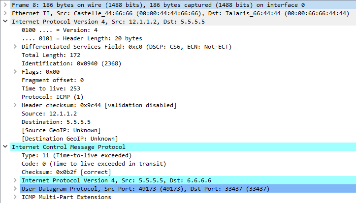
PE-2 receives the packet, and label switches it back over the MPLS core towards PE-1. PE-1 will forward the packet to CE-1. CE-1 finally receives the “TTL Exceeded” message that was originated by P1. This is when 12.1.1.2 shows up as the second hop in the traceroute performed on CE-1. This completes the second step of the traceroute process and allows CE-1 to record the next hop in the path. The process repeats with CE-1 incrementing the TTL value with each probe until CE-1 finally receives an ICMP “Port Unreachable” message from the destination.
In conclusion, when a traceroute is performed in an MPLS environment, the ICMP “TTL Exceeded” messages are generated at each hop. Since the intermediate LSRs in the MPLS core cannot IP route the packets back to the source, these messages travel the entire length of the MPLS network to the remote CE router. The remote CE router then sends the ICMP messages back to the original sender.
- Mark as Read
- Mark as New
- Bookmark
- Permalink
- Report Inappropriate Content
Excellent article. Thank you for posting !!!
- Mark as Read
- Mark as New
- Bookmark
- Permalink
- Report Inappropriate Content
Awesome post !!!.
- Mark as Read
- Mark as New
- Bookmark
- Permalink
- Report Inappropriate Content
Thanks NetOps Chennai and vadivelperiyasamy!
Find answers to your questions by entering keywords or phrases in the Search bar above. New here? Use these resources to familiarize yourself with the community: