- Cisco Community
- Technology and Support
- Networking
- Networking Knowledge Base
- FabricPath: Cisco’s New Technology of Extending Layer 2 Network Without Spanning Tree
- Subscribe to RSS Feed
- Mark as New
- Mark as Read
- Bookmark
- Subscribe
- Printer Friendly Page
- Report Inappropriate Content
- Subscribe to RSS Feed
- Mark as New
- Mark as Read
- Bookmark
- Subscribe
- Printer Friendly Page
- Report Inappropriate Content
12-16-2010 02:29 PM - edited 03-01-2019 04:35 PM
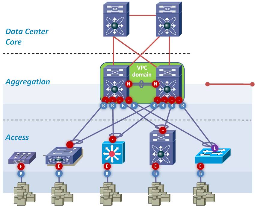
The traditional Ethernet network designs require termination of the Layer 2 Network at Aggregation or Core layer to limit the fault isolation and broadcast domain due to spanning tree. Due to limitations of spanning tree, each network design is composed of both Layer 2 and Layer 3 to take advantage of routing features (e.g. multipathing and fast convergence, loop mitigation mechanisms like TTL, RPF) to extend their network as shown in Figure 1 below. Cisco's new technology, FabricPath, brings Layer 3 routing benefits to flexible Layer 2-bridged Ethernet networks.

Figure 1
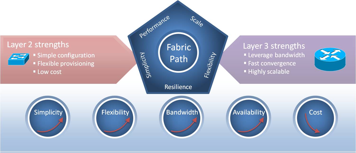
Due to widespread use of virtualization and clustering technologies these days, many organizations are looking to extend their Layer 2 domains across multiple data centers. FabricPath can provide this solution because it has the reliability and HA (High Availability) features just like ISIS protocol. Figure 2 shows the key points of FabricPath from both a Layer 2 and Layer 3 prospective.

Figure 2
Currently FabricPath is available only on the F1-Series module of the Nexus 7000 series. FabricPath is derived from IT Standard TRILL technology with a lot of extra enhanced features. Its switching allows multipath forwarding at the Layer 2 without the use of spanning-tree. FabricPath uses layer 2 ISIS based protocol for its control plane. The FabricPath ISIS process is different than the layer 3 ISIS process.
.
FP Forwarding Mechanism:
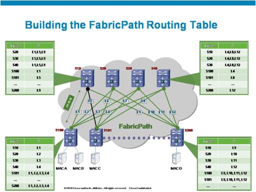
FabricPath creates trees just like spanning tree but uses link-based control based on ISIS protocol rather than distance vector like spanning tree. This is why it is loop free. This allows FabricPath to be in a forwarding state on all paths (maximum 16) without any blocking. It also allows faster convergences in case of failure similar to routing protocol. As shown in Figure 3, the fabric topology is composed of ingress, egress (edge) switches that are connected to the hosts and core switches that provide the fabric to connect all the edge switches. The egress switch can have the ports connected to conventional Ethernet (CE) so the egress switch is the one that has interfaces that are part of fabric path and CE. To forward the traffic to multiple destinations, FabricPath creates the Tree. After electing common roots for the L2 Fabric, "trees" from these roots are calculated from the shared L2 IS-IS routing database. In FB topology, each switch gets a unique switch ID, as depicted in Figure 3, to create the Layer 2 routing table. The ingress switch determines the "Tree" to be used for a flow and add the unique Tree identifier into the Fabric Path header.
Figure 3 depicts the Fabric Path routing table view from each switch. As mentioned before, once the root of the tree is determined, the root assigns dynamic IDs to the members.

Figure 3
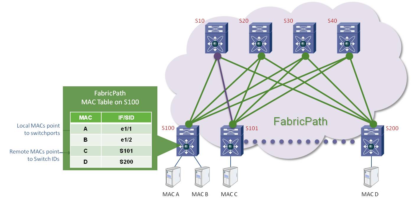
One of the major improvements in FabricPath is that not all the switches in the Layer 2 FabricPath domain have to learn all the MAC addresses, which helps scale the MAC address tables. In FabricPath, as shown in figure 4, the MAC address table of the host A where it is showing that the host B is connected locally on the CE, whereas host C and D are connected via FP to the remote switches 101 and 200. When the Host A needs to send traffic to host C and host C's MAC address is not known, it floods the traffic to its root tree and then root forwards the packets to all its member switches. If the destination is not known on a particular edge switch, the switch drops that frame and does not learn the MAC address. However, if the destination is present on that switch, it will keep the source MAC address. To help reduce the MAC address entries, the core FabricPath switches never learn the MAC addresses.

Figure 4
FP Configuration:
FabricPath is fairly simple to configure. To configure the basic FabricPath network, follow the following steps on each device:
- Enable the FP feature set on each device.
switch# config t
switch(config)# feature-set fabricpath
- Configure the FP interfaces.
Switch(config)# interface ethernet 1/1
Switch(configif)# switchport mode fabric
- Set the VLAN into FabricPath Mode. The default is the CE VLAN mode.
switch(config)# vlan 10
switch(config-vlan)# mode fabricpath
Please visit Cisco.com for more information about FabricPath.
- Mark as Read
- Mark as New
- Bookmark
- Permalink
- Report Inappropriate Content
This document is close to worthless. The information on the drawings is illegible and out of focus. Moreover, the explanation is poor and the grammar is lacking. This is beneath Cisco.
- Mark as Read
- Mark as New
- Bookmark
- Permalink
- Report Inappropriate Content
I apologize that the image in Figure 3 is so blurry, I don't have a way to make it any clearer.
I am told that there is a more updated doc about Fabric Path, try this configuration guide:
- Mark as Read
- Mark as New
- Bookmark
- Permalink
- Report Inappropriate Content
We recently conducted a webinar on FabricPath (link to recording) that you may find helpful.
About the webinar: Cisco FabricPath is an innovation that simplifies Layer 2 switching by removing spanning tree and replacing it with IS-IS. FabricPath facilitates bandwidth provisioning, use efficient multipathing, provides safe forwarding for unicast and multicast frames, simplifies the design and reduces the costs of network and application deployment and operation. Slides are available at: http://www.slideshare.net/getyourbuildon/fabric-path-webinar
Hope this is helpful!
Find answers to your questions by entering keywords or phrases in the Search bar above. New here? Use these resources to familiarize yourself with the community: