- Cisco Community
- Technology and Support
- Networking
- Other Network Architecture Subjects
- So i was struggling with this
- Subscribe to RSS Feed
- Mark Topic as New
- Mark Topic as Read
- Float this Topic for Current User
- Bookmark
- Subscribe
- Mute
- Printer Friendly Page
how to configure cisco firepower run IPS mode on ISR
- Mark as New
- Bookmark
- Subscribe
- Mute
- Subscribe to RSS Feed
- Permalink
- Report Inappropriate Content
08-17-2015 07:56 PM - edited 03-03-2019 07:57 AM
Dear,
I'm having problems configuring the connection between firepower and isr4k. I have to follow the instructions in the link below, but I do not understand how to communicate with the Router and firepower.
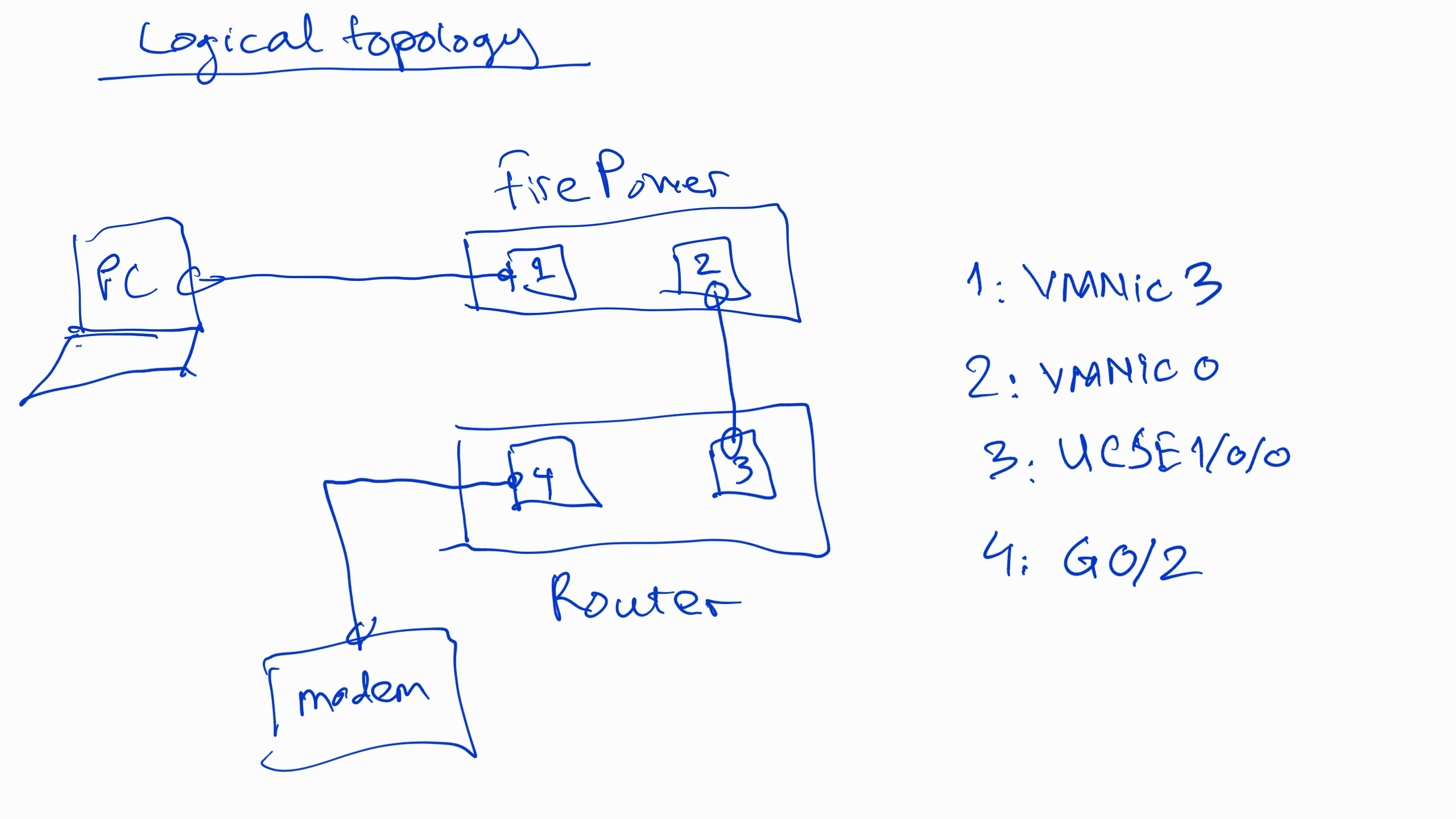
My LAB have ISR4k with license appk9 and securityk9, while firepower is installed in blade UCS-E 160D, and FireSight too. My Client PC connect to a Switch, and this switch link to port Ge2 on UCSE-160D. I attached the topology below.
I have problem when my client PC cannot communicate with Gateway is interface BDI100 on Router. Gateway cannot ping to PC, too.
When I use command "show traffic-statistics" in firepower's console, I didnt see any TX or RX packet in interface External (Interface connect to VMNIC0), but Interface Internal (Interface connect to VMNIC3) have. So, I think i have mistake when configure communicate between firepower and Router. I attached the configuration of Router below.
Please help me to solved my problem.
Thanks!
- Labels:
-
Other Networking
- Mark as New
- Bookmark
- Subscribe
- Mute
- Subscribe to RSS Feed
- Permalink
- Report Inappropriate Content
12-08-2015 12:14 PM
Did you ever figure this out? I'm following the link below, it's very unclear how the BDI interfaces work... more specifically what the 10.1.1.1 interface is in the example.
- Mark as New
- Bookmark
- Subscribe
- Mute
- Subscribe to RSS Feed
- Permalink
- Report Inappropriate Content
02-10-2016 09:48 AM
So i was struggling with this too, but eventually got it working. My scenario is specific to the 4331-X, and single wide UCS-E blade. The difference being the way that UCS-E interfaces and vmnic's are mapped internally compared to other ISR model routers.
I'm not sure if there are other deployment models, in my case I used the UCS front panel G2 port.
These are the next steps once you get the CIMC configured, ESXI installed and the virtual sensor deployed.
The SourceFIRE virtual sensor will have three interfaces when deployed in ESXI. They all need to map to individual vmnics in ESXI.
The first interface I mapped to vm network (which in my case was vmnic0), for OOB management. The gateway for that interface exists on the router on the UCS1/0/0 interface. you also have to have a route that points to the IP of the sensors management interface exiting the UCS1/0/0 interface (as the gateway for the route). my sensor IP is 10.10.10.254. so I have a route on the router to get to it as such:
ip route 10.10.10.254 255.255.255.255 ucs1/0/0
For the second and third interfaces (the tricky ones) on the sensor I created individual vSwitches for each, and each vswitch has a vmnic mapped to it. In my case vmnic1 (ucs1/0/1) for egress traffic.
the third interface of the sensor is vmnic2 which maps to the front panel UCS-E series port labeled G2. This is my ingress interface, that plugs in directly to my switch, where user traffic originates from.
the order isn't important as long as you have the physical interfaces, UCS-E interfaces, sourcefire inspection interfaces (internal,external) and vmnic's mapped correctly. If you are unsure check the MAC addresses, they should all align.
So in my case, client traffic originates from a layer 2 switch, and the clients default gateway for each VLAN is a BDI interface on the router with both the encapsulation set and the tag rewrite command configured just as described in the security configuration guide for FirePOWER ISR.
UTD redirection commands were unnecessary for my deployment.
- Mark as New
- Bookmark
- Subscribe
- Mute
- Subscribe to RSS Feed
- Permalink
- Report Inappropriate Content
02-09-2016 02:27 PM
Did either of you guys figure this out? I'm in the same boat...
Discover and save your favorite ideas. Come back to expert answers, step-by-step guides, recent topics, and more.
New here? Get started with these tips. How to use Community New member guide