- Cisco Community
- Technology and Support
- Networking
- Routing
- Inter VLAN routing: Can ping default VLAN IP from other VLAN's but no further. Default VLAN IP not ...
- Subscribe to RSS Feed
- Mark Topic as New
- Mark Topic as Read
- Float this Topic for Current User
- Bookmark
- Subscribe
- Mute
- Printer Friendly Page
- Mark as New
- Bookmark
- Subscribe
- Mute
- Subscribe to RSS Feed
- Permalink
- Report Inappropriate Content
12-02-2019 11:28 AM - edited 12-02-2019 12:14 PM
Hi All,
Please bear with me as I'm new to this and relatively new to Networking at this level.
I'm trying to set up inter VLAN routing. Following this post:
I've configured everything I could (or perhaps almost everything except for 6) Configure the interface to the default router. part. ). This is an older Cisco 3750G switch:
VLAN1 192.168.0 (IP 192.168.0.3, Secondary 192.168.0.4)
VLAN2 10.0.0.0 ( IP 10.0.0.1 )
VLAN3 10.1.0.0 ( IP 10.1.0.1 )
VLAN4 10.2.0.0 ( IP 10.2.0.1 )
Now from the switch itself, I can ping all IP's without any issues. For example, I can ping 192.168.0.100 from the switch but not from within VLAN 2 devices. However, I can ping 192.168.0.3 and 192.168.0.4 (secondary), the switch VLAN 1 IP's from within devices on VLAN 2.
Devices on VLAN2 can ping each other, the VLAN IP and even the default VLAN (Switch IP) 192.168.0.3 and 192.168.0.4 above. But nothing beyond the two VLAN 1 IP's above. What am I missing? My first thought is missing trunking or a setting on VLAN1 but I'm not 100% on that nor what those commands would be.
Thx,
mdscisco01#show ip route
Codes: C - connected, S - static, R - RIP, M - mobile, B - BGP
       D - EIGRP, EX - EIGRP external, O - OSPF, IA - OSPF inter area
       N1 - OSPF NSSA external type 1, N2 - OSPF NSSA external type 2
       E1 - OSPF external type 1, E2 - OSPF external type 2
       i - IS-IS, su - IS-IS summary, L1 - IS-IS level-1, L2 - IS-IS level-2
       ia - IS-IS inter area, * - candidate default, U - per-user static route
       o - ODR, P - periodic downloaded static route

Gateway of last resort is 192.168.0.1 to network 0.0.0.0

     10.0.0.0/24 is subnetted, 1 subnets
C       10.0.0.0 is directly connected, Vlan2
C    192.168.0.0/24 is directly connected, Vlan1
S*   0.0.0.0/0 [1/0] via 192.168.0.1
mdscisco01#
Solved! Go to Solution.
- Labels:
-
Other Routing
Accepted Solutions
")

- Mark as New
- Bookmark
- Subscribe
- Mute
- Subscribe to RSS Feed
- Permalink
- Report Inappropriate Content
12-04-2019 03:02 PM
Please, check it:
!
no ip default-gateway 192.168.0.3
I think that your Asus is not enabled OSPF then it will not work.
I suggest to your first, create a three static route in your ASUS and test again, like below;
ip route 10.0.0.1 255.255.255.0 192.168.0.1
ip route 10.1.0.0 255.255.255.0 192.168.0.1
ip route 10.2.0.0 255.255.255.0 192.168.0.1
ip route 10.3.0.0 255.255.255.0 192.168.0.1
if it work, try enable OSPF in your ASUS ROUTER and remove this static routes and test again..
Regards,
*** Rate All Helpful Responses ***
- Mark as New
- Bookmark
- Subscribe
- Mute
- Subscribe to RSS Feed
- Permalink
- Report Inappropriate Content
12-05-2019 02:59 AM
*** Rate All Helpful Responses ***
- Mark as New
- Bookmark
- Subscribe
- Mute
- Subscribe to RSS Feed
- Permalink
- Report Inappropriate Content
12-05-2019 08:42 AM - edited 12-05-2019 08:45 AM
Hello
So I guess you are saying static or ospf routing internet access is applicable for only vlan 1?
I assume the Asus is aware of your Lans subnets - be it via static routes pointing back towards your cisco switch or them being learnt via opsf from the cisco switch?
If so that leaves Network Translation ( NAT) on the Asus.
Chain POSTROUTING (policy ACCEPT)
target     prot opt source               destination
SNAT       0    --  0.0.0.0/0            0.0.0.0/0           to:192.168.0.6
SNAT       0    --  192.168.0.0/24       0.0.0.0/0           to:123.123.123.321
SNAT       0    --  192.168.45.0/24      0.0.0.0/0           to:123.123.123.321
SNAT       0    --  192.168.75.0/24      0.0.0.0/0           to:123.123.123.321
MASQUERADE  0    --  0.0.0.0/0            0.0.0.0/0           mark match 0x80000000/0x80000000
MASQUERADE  0    --  10.1.1.0/24          0.0.0.0/0
I dont see any translation for those other subnets in this output so does your Asus nat configuration need to be updated to accomodate these other vlans - Have you done this?
cisco
Sh ip route
Please rate and mark as an accepted solution if you have found any of the information provided useful.
This then could assist others on these forums to find a valuable answer and broadens the community’s global network.
Kind Regards
Paul
- Mark as New
- Bookmark
- Subscribe
- Mute
- Subscribe to RSS Feed
- Permalink
- Report Inappropriate Content
12-05-2019 09:24 AM
1. Nat configuration
2. Route back.
*** Rate All Helpful Responses ***
- Mark as New
- Bookmark
- Subscribe
- Mute
- Subscribe to RSS Feed
- Permalink
- Report Inappropriate Content
12-10-2019 12:12 AM - edited 12-10-2019 12:31 AM
Hello
You have duplicate addressing in your ospf config and missing statements also!
And why do you have the same subnets on both devices, surely the cisco is the device for the intervlan routing so you dont need those same interfaces/subnet on the router?
Only ospf statements on the asus which relates to its connect interface towards the cisco is required( whatever that may be) and obviously any wan interface/subnets - what ever they maybe
AsusRouter
router ospf
log-adjacency-changes
ospf router-id 192.168.0.6
no network 10.0.0.1/24 area 0 <---INCORRECT duplicate ip of the cisco vlan 2 needs to the router own ip
no network 10.1.0.1/24 area 0 <---INCORRECT duplicate ip of the cisco vlan 3 needs to the router own ip
no network 10.2.0.1/24 area 0 <---INCORRECT duplicate ip of the cisco vlan 4 needs to the router own ip
no network 10.3.0.1/24 area 0 <---INCORRECT duplicate ip of the cisco vlan 5 needs to the router own ip
no network 192.168.0.1/24 area 0 <---INCORRECT duplicate ip of the cisco vlan 1 needs to the router own ip
Cisco 3750G
router ospf 1
< vlan 2 doesn't exit
network 10.1.0.1 0.0.0.0 area 0 <- vlan 3
network 10.2.0.1 0.0.0.0 area 0 <-vlan 4
network 10.3.0.1 0.0.0.0 area 0 <-vlan 5
network 10.4.0.1 0.0.0.0 area 0 < no l3 interface for this vlan , IF NOT NEEDED REMOVE IT
network 192.168.0.1 0.0.0.0 area 0 <-vlan1
router ospf 1
passive interface default <-- if applicable
no passive interface vlan x<-- if applicable to the interface/vlan connected towards asus
network 10.0.0.1 0.0.0.0 area
network 10.4.0.1 0.0.0.0 area 0 <-- if applicable
no p default-gateway 192.168.0.1 ---not needed
no ip route 0.0.0.0 0.0.0.0 Vlan1 192.168.0.6 <---not needed
int vlan x
ip opsf mtu-ignore < applied to then interface /vlan connected towards the asus
int vlan 4 <-- If applicable
ip address 10.4.0.1 255.255.255.0
Please rate and mark as an accepted solution if you have found any of the information provided useful.
This then could assist others on these forums to find a valuable answer and broadens the community’s global network.
Kind Regards
Paul
- Mark as New
- Bookmark
- Subscribe
- Mute
- Subscribe to RSS Feed
- Permalink
- Report Inappropriate Content
12-12-2019 06:44 AM - edited 12-12-2019 07:36 AM
Hello
What I mean is -
In your routers configurations you show them advertising the Cisco switches subnets - You don’t need to do that.
In a basic ospf setup between devices you would enable ospf only on the interfaces that require opsf adjacency on them and then disable any other interfaces you don’t won’t ospf to run on, then you just advertised those other interfaces in ospf.
Example:
RTRx
Int xx
ip address 1.1.1.1 255 255.255.0
int yy
ip address 2,2,2,2 255.255.255.0
router ospf x
passive interface-default
no passive interface xx
network 1.1.1.1 0.0.0.0 area 0
network 2.2.2.2 0.0.0.0 area 0
As you see only int xx will be running ospf and int yy subnet will just be advertised
Any other subnet/addressing relating to another routers interface then you don’t advertise them.
Please rate and mark as an accepted solution if you have found any of the information provided useful.
This then could assist others on these forums to find a valuable answer and broadens the community’s global network.
Kind Regards
Paul
- Mark as New
- Bookmark
- Subscribe
- Mute
- Subscribe to RSS Feed
- Permalink
- Report Inappropriate Content
12-02-2019 12:00 PM - edited 12-02-2019 12:02 PM
"But nothing beyond the two VLAN 1 IP's above" <<--- as per the document you have router, Do you routing enabled on cisco Switch and pointed defaut route to router side, and router should have also route back to your network point to switch IP adddess
Example Switch side :
Configure the default route for the switch.
Switch(config)#ip route 0.0.0.0 0.0.0.0 x.x.x
EDIT :
i have missed your routing output somehow how.
S* 0.0.0.0/0 [1/0] via 192.168.0.1
You mean from your IP range not reaching beyond Router you mean? to the internet ?
Can you post switch and router config ?
- Mark as New
- Bookmark
- Subscribe
- Mute
- Subscribe to RSS Feed
- Permalink
- Report Inappropriate Content
12-02-2019 12:17 PM - edited 12-02-2019 12:18 PM
You didn't miss. I was editing the post with further information. I should have replied below with the extra details instead of keeping it together in the original post.
From the switch itself, I can ping outside to places such as 8.8.8.8. But not from VLAN 2 for example.
Please see below.
mdscisco01#
mdscisco01#show ip int vlan 1
Vlan1 is up, line protocol is up
  Internet address is 192.168.0.3/24
  Broadcast address is 255.255.255.255
  Address determined by setup command
  MTU is 1500 bytes
  Helper address is not set
  Directed broadcast forwarding is disabled
  Secondary address 192.168.0.4/24
  Outgoing access list is not set
  Inbound  access list is not set
  Proxy ARP is enabled
  Local Proxy ARP is disabled
  Security level is default
  Split horizon is enabled
  ICMP redirects are always sent
  ICMP unreachables are always sent
  ICMP mask replies are never sent
  IP fast switching is enabled
  IP CEF switching is enabled
  IP CEF switching turbo vector
  IP Null turbo vector
  IP multicast fast switching is enabled
  IP multicast distributed fast switching is disabled
  IP route-cache flags are Fast, CEF
  Router Discovery is disabled
  IP output packet accounting is disabled
  IP access violation accounting is disabled
  TCP/IP header compression is disabled
  RTP/IP header compression is disabled
  Probe proxy name replies are disabled
  Policy routing is disabled
  Network address translation is disabled
  BGP Policy Mapping is disabled
  WCCP Redirect outbound is disabled
  WCCP Redirect inbound is disabled
  WCCP Redirect exclude is disabled
mdscisco01#
mdscisco01#
mdscisco01#show ip int vlan 2
Vlan2 is up, line protocol is up
  Internet address is 10.0.0.1/24
  Broadcast address is 255.255.255.255
  Address determined by setup command
  MTU is 1500 bytes
  Helper address is not set
  Directed broadcast forwarding is disabled
  Outgoing access list is not set
  Inbound  access list is not set
  Proxy ARP is enabled
  Local Proxy ARP is disabled
  Security level is default
  Split horizon is enabled
  ICMP redirects are always sent
  ICMP unreachables are always sent
  ICMP mask replies are never sent
  IP fast switching is enabled
  IP CEF switching is enabled
  IP CEF switching turbo vector
  IP Null turbo vector
  IP multicast fast switching is enabled
  IP multicast distributed fast switching is disabled
  IP route-cache flags are Fast, CEF
  Router Discovery is disabled
  IP output packet accounting is disabled
  IP access violation accounting is disabled
  TCP/IP header compression is disabled
  RTP/IP header compression is disabled
  Probe proxy name replies are disabled
  Policy routing is disabled
  Network address translation is disabled
  BGP Policy Mapping is disabled
  WCCP Redirect outbound is disabled
  WCCP Redirect inbound is disabled
  WCCP Redirect exclude is disabled
mdscisco01#show ip int vlan 3
Vlan3 is up, line protocol is down
  Internet address is 10.1.0.1/24
  Broadcast address is 255.255.255.255
  Address determined by setup command
  MTU is 1500 bytes
  Helper address is not set
  Directed broadcast forwarding is disabled
  Outgoing access list is not set
  Inbound  access list is not set
  Proxy ARP is enabled
  Local Proxy ARP is disabled
  Security level is default
  Split horizon is enabled
  ICMP redirects are always sent
  ICMP unreachables are always sent
  ICMP mask replies are never sent
  IP fast switching is enabled
  IP CEF switching is enabled
  IP CEF switching turbo vector
  IP Null turbo vector
  IP multicast fast switching is enabled
  IP multicast distributed fast switching is disabled
  IP route-cache flags are Fast, CEF
  Router Discovery is disabled
  IP output packet accounting is disabled
  IP access violation accounting is disabled
  TCP/IP header compression is disabled
  RTP/IP header compression is disabled
  Probe proxy name replies are disabled
  Policy routing is disabled
  Network address translation is disabled
  BGP Policy Mapping is disabled
  WCCP Redirect outbound is disabled
  WCCP Redirect inbound is disabled
  WCCP Redirect exclude is disabled
mdscisco01#show ip int vlan 4
Vlan4 is up, line protocol is down
  Internet address is 10.2.0.1/24
  Broadcast address is 255.255.255.255
  Address determined by setup command
  MTU is 1500 bytes
  Helper address is not set
  Directed broadcast forwarding is disabled
  Outgoing access list is not set
  Inbound  access list is not set
  Proxy ARP is enabled
  Local Proxy ARP is disabled
  Security level is default
  Split horizon is enabled
  ICMP redirects are always sent
  ICMP unreachables are always sent
  ICMP mask replies are never sent
  IP fast switching is enabled
  IP CEF switching is enabled
  IP CEF switching turbo vector
  IP Null turbo vector
  IP multicast fast switching is enabled
  IP multicast distributed fast switching is disabled
  IP route-cache flags are Fast, CEF
  Router Discovery is disabled
  IP output packet accounting is disabled
  IP access violation accounting is disabled
  TCP/IP header compression is disabled
  RTP/IP header compression is disabled
  Probe proxy name replies are disabled
  Policy routing is disabled
  Network address translation is disabled
  BGP Policy Mapping is disabled
  WCCP Redirect outbound is disabled
  WCCP Redirect inbound is disabled
  WCCP Redirect exclude is disabled
mdscisco01#
mdscisco01#show ip int g1/0/24/
                              ^
% Invalid input detected at '^' marker.

mdscisco01#show ip int g1/0/24
GigabitEthernet1/0/24 is down, line protocol is down
  Inbound  access list is not set
mdscisco01#show int g1/0/24
GigabitEthernet1/0/24 is down, line protocol is down (notconnect)
  Hardware is Gigabit Ethernet, address is 001c.57ae.f818 (bia 001c.57ae.f818)
  MTU 1500 bytes, BW 10000 Kbit, DLY 1000 usec,
     reliability 255/255, txload 1/255, rxload 0/255
  Encapsulation ARPA, loopback not set
  Keepalive set (10 sec)
  Auto-duplex, Auto-speed, media type is 10/100/1000BaseTX
  input flow-control is off, output flow-control is unsupported
  ARP type: ARPA, ARP Timeout 04:00:00
  Last input never, output never, output hang never
  Last clearing of "show interface" counters never
  Input queue: 0/75/0/0 (size/max/drops/flushes); Total output drops: 85
  Queueing strategy: fifo
  Output queue: 0/40 (size/max)
  5 minute input rate 0 bits/sec, 0 packets/sec
  5 minute output rate 0 bits/sec, 0 packets/sec
     835405434 packets input, 1610692541 bytes, 0 no buffer
     Received 36457959 broadcasts (12240346 multicasts)
     0 runts, 0 giants, 0 throttles
     0 input errors, 0 CRC, 0 frame, 0 overrun, 0 ignored
     0 watchdog, 12240346 multicast, 0 pause input
     0 input packets with dribble condition detected
     1683612558 packets output, 2565355401 bytes, 0 underruns
     0 output errors, 0 collisions, 2 interface resets
     0 babbles, 0 late collision, 0 deferred
     0 lost carrier, 0 no carrier, 0 PAUSE output
     0 output buffer failures, 0 output buffers swapped out
mdscisco01#
- Mark as New
- Bookmark
- Subscribe
- Mute
- Subscribe to RSS Feed
- Permalink
- Report Inappropriate Content
12-02-2019 12:25 PM - edited 12-02-2019 12:37 PM
There is a second switch sitting at 192.168.0.1 which is a basic Asus GigE / Wireless device. However, I don't see that it would cause any issues here since the issue appears isolated to the Cisco 3750G side.
mdscisco01#
mdscisco01#show vlan

VLAN Name                             Status    Ports
---- -------------------------------- --------- -------------------------------
1    default                          active    Gi1/0/1, Gi1/0/2, Gi1/0/3, Gi1/0/4, Gi1/0/6, Gi1/0/7, Gi1/0/8, Gi1/0/9, Gi1/0/11
                                                Gi1/0/12, Gi1/0/13, Gi1/0/14, Gi1/0/15, Gi1/0/16, Gi1/0/17, Gi1/0/18, Gi1/0/19
                                                Gi1/0/20, Gi1/0/21, Gi1/0/22, Gi1/0/23, Gi1/0/24, Gi1/0/25, Gi1/0/26, Gi1/0/27
                                                Gi1/0/28
2    VLAN0002                         active    Gi1/0/5, Gi1/0/10
3    VLAN0003                         active
4    VLAN0004                         active
1002 fddi-default                     act/unsup
1003 token-ring-default               act/unsup
1004 fddinet-default                  act/unsup
1005 trnet-default                    act/unsup

VLAN Type  SAID       MTU   Parent RingNo BridgeNo Stp  BrdgMode Trans1 Trans2
---- ----- ---------- ----- ------ ------ -------- ---- -------- ------ ------
1    enet  100001     1500  -      -      -        -    -        0      0
2    enet  100002     1500  -      -      -        -    -        0      0
3    enet  100003     1500  -      -      -        -    -        0      0
4    enet  100004     1500  -      -      -        -    -        0      0
1002 fddi  101002     1500  -      -      -        -    -        0      0
1003 tr    101003     1500  -      -      -        -    -        0      0
1004 fdnet 101004     1500  -      -      -        ieee -        0      0
1005 trnet 101005     1500  -      -      -        ibm  -        0      0

Remote SPAN VLANs
------------------------------------------------------------------------------


Primary Secondary Type              Ports
------- --------- ----------------- ------------------------------------------

mdscisco01#
- Mark as New
- Bookmark
- Subscribe
- Mute
- Subscribe to RSS Feed
- Permalink
- Report Inappropriate Content
12-02-2019 12:53 PM
users ---different VLAN--Switch 3750--Asus--Internet <- is this correct?
192.168.0.1 which is a basic Asus GigE / Wireless device - this means from switch or IP from 192.168.0.X working but other VLAN not working for internet, is this correct? in this case, you do not have NAT policies for that IP, please follow below guide to setup.
- Mark as New
- Bookmark
- Subscribe
- Mute
- Subscribe to RSS Feed
- Permalink
- Report Inappropriate Content
12-02-2019 02:46 PM
@balaji.bandi wrote:users ---different VLAN--Switch 3750--Asus--Internet <- is this correct?
192.168.0.1 which is a basic Asus GigE / Wireless device - this means from switch or IP from 192.168.0.X working but other VLAN not working for internet, is this correct? in this case, you do not have NAT policies for that IP, please follow below guide to setup.
https://www.asus.com/support/FAQ/1011715/
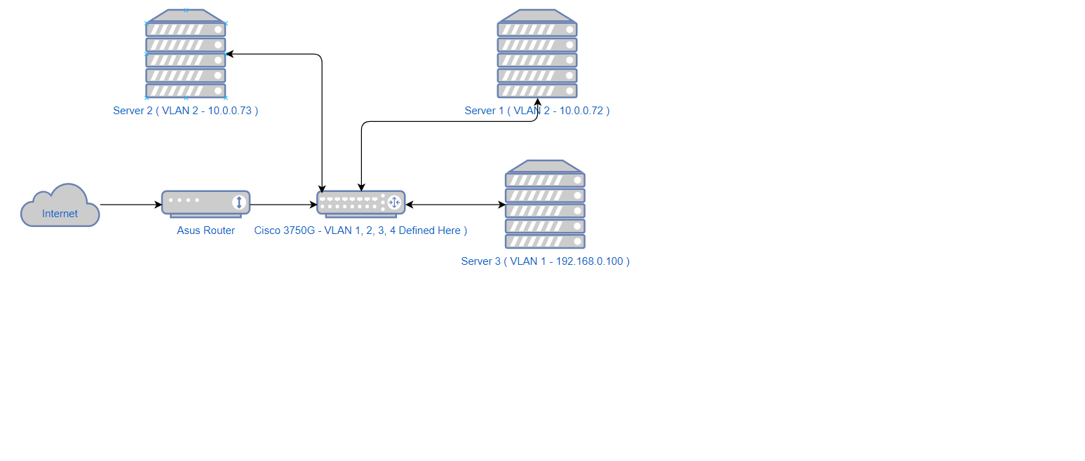
Yes, this is just a simple two-switch network:
Users / Lab Servers -- Switch 3750 (VLAN 1, 2, 3, 4 exist on this switch ) ( G/1/0/24 ) --Asus -- Internet
Looking from the perspective of the issue, it's even simpler. Servers with IP's on different VLAN's connected to each other VIA the Cisco 3750G are not communicating. So the issue exists even with the Asus router out of the picture. So for example, Server 3 with IP 192.168.0.100 ( VLAN 1 ) can't be reached from servers on VLAN 2.
Thx,
mdscisco01#show running-config
Building configuration...

Current configuration : 2153 bytes
!
version 12.2
no service pad
service timestamps debug uptime
service timestamps log uptime
no service password-encryption
!
hostname mdscisco01
!
enable secret 5 <SECRET>
enable password <SECRET>
!
username cisco password 0 <SECRET>
aaa new-model
aaa authentication login default local
aaa authentication enable default enable
!
aaa session-id common
switch 1 provision ws-c3750g-24ps
system mtu routing 1500
ip subnet-zero
ip routing
!
!
!
!
!
!
!
!
!
spanning-tree mode pvst
spanning-tree extend system-id
!
vlan internal allocation policy ascending
!
!
!
!
interface GigabitEthernet1/0/1
!
interface GigabitEthernet1/0/2
!
interface GigabitEthernet1/0/3
!
interface GigabitEthernet1/0/4
!
interface GigabitEthernet1/0/5
 switchport access vlan 2
 switchport mode access
!
interface GigabitEthernet1/0/6
!
interface GigabitEthernet1/0/7
!
interface GigabitEthernet1/0/8
!
interface GigabitEthernet1/0/9
!
interface GigabitEthernet1/0/10
 switchport access vlan 2
 switchport mode access
!
interface GigabitEthernet1/0/11
!
interface GigabitEthernet1/0/12
!
interface GigabitEthernet1/0/13
!
interface GigabitEthernet1/0/14
!
interface GigabitEthernet1/0/15
!
interface GigabitEthernet1/0/16
!
interface GigabitEthernet1/0/17
!
interface GigabitEthernet1/0/18
!
interface GigabitEthernet1/0/19
!
interface GigabitEthernet1/0/20
!
interface GigabitEthernet1/0/21
 ip verify source
!
interface GigabitEthernet1/0/22
!
interface GigabitEthernet1/0/23
!
interface GigabitEthernet1/0/24
 switchport trunk allowed vlan 1-4
!
interface GigabitEthernet1/0/25
!
interface GigabitEthernet1/0/26
!
interface GigabitEthernet1/0/27
!
interface GigabitEthernet1/0/28
!
interface Vlan1
 ip address 192.168.0.4 255.255.255.0 secondary
 ip address 192.168.0.3 255.255.255.0
!
interface Vlan2
 ip address 10.0.0.1 255.255.255.0
!
interface Vlan3
 ip address 10.1.0.1 255.255.255.0
!
interface Vlan4
 ip address 10.2.0.1 255.255.255.0
!
ip default-gateway 192.168.0.1
ip classless
ip route 0.0.0.0 0.0.0.0 192.168.0.1
ip http server
ip http secure-server
!
!
radius-server source-ports 1645-1646
!
control-plane
!
!
line con 0
line vty 5 15
!
end

mdscisco01#
- Mark as New
- Bookmark
- Subscribe
- Mute
- Subscribe to RSS Feed
- Permalink
- Report Inappropriate Content
12-04-2019 03:48 PM - edited 12-04-2019 03:55 PM
Hello
mdscisco01# ip routing interface GigabitEthernet1/0/24 <----WHY a trunk, why not a access port in vlan 1?switchport trunk allowed vlan 1-4switchport mode access
switchport access vlan 1
spanning-tree portfastip address 192.168.0.4 255.255.255.0 secondary Why do you have this? ip address 192.168.0.3 255.255.255.0 ! interface Vlan2 ip address 10.0.0.1 255.255.255.0 ! interface Vlan3 ip address 10.1.0.1 255.255.255.0 ! interface Vlan4 ip address 10.2.0.1 255.255.255.0 !ip default-gateway 192.168.0.1ip route 0.0.0.0 0.0.0.0 192.168.0.1
vlan 2-4
exit
All access ports
int x/x
switchport mode access
spanning-tree portfast
switchport access vlan xx
Asus
On this Asus rtr do you have static routes back towards the core switch for those lan subnets
ip route 10.0.0.0 255.255.255.0 192.168.0.3
ip route 10.1.0.0 255.255.255.0 192.168.0.3
ip route 10.2.0.0 255.255.255.0 192.168.0.3
Lastly you will also need NAT statements on this Asus rtr that relate to the lan subnets so to allow internet access for them?
Please rate and mark as an accepted solution if you have found any of the information provided useful.
This then could assist others on these forums to find a valuable answer and broadens the community’s global network.
Kind Regards
Paul
- Mark as New
- Bookmark
- Subscribe
- Mute
- Subscribe to RSS Feed
- Permalink
- Report Inappropriate Content
12-04-2019 07:40 PM
@paul driver thank you, however, I already solved the original problem in this post simply by changing the IP of the Asus router alongside changing the IP of the Cisco 3750G router.

- Mark as New
- Bookmark
- Subscribe
- Mute
- Subscribe to RSS Feed
- Permalink
- Report Inappropriate Content
12-02-2019 12:45 PM
Hi @Tom
Could you attach a diagram of your network?
Just to rule out, did you try disabling the PC firewall?
Regards
- Mark as New
- Bookmark
- Subscribe
- Mute
- Subscribe to RSS Feed
- Permalink
- Report Inappropriate Content
12-02-2019 02:47 PM
@luis_cordova wrote:Hi @Tom
Could you attach a diagram of your network?
Just to rule out, did you try disabling the PC firewall?
Regards
Correct. Firewalls are off.
- Mark as New
- Bookmark
- Subscribe
- Mute
- Subscribe to RSS Feed
- Permalink
- Report Inappropriate Content
12-02-2019 04:22 PM
Experimented further to get some more information. I took one of the VLAN 2 devices and stuck it on VLAN 3. Now I tried to ping and ssh between the two devices. Both worked. Just doesn't work with default VLAN 1 . Thinking this has to do with this step:
6. Configure the interface to the default router. In this scenario you have a Layer 3 FastEthernet port.
Switch(config)#interface FastEthernet 0/1
Switch(config-if)#no switchport
Switch(config-if)#ip address 200.1.1.1 255.255.255.0
Switch(config-if)#no shutdown
However, when I try this (g1/0/24 - Port connected to my Asus Router ), I get this:
mdscisco01#
mdscisco01#conf t
Enter configuration commands, one per line. End with CNTL/Z.
mdscisco01(config)#int g1/0/24
mdscisco01(config-if)#no switchport
mdscisco01(config-if)#ip address 192.168.0.6 255.255.255.0
192.168.0.0 overlaps with Vlan1
mdscisco01(config-if)#no shut
mdscisco01(config-if)#
- Mark as New
- Bookmark
- Subscribe
- Mute
- Subscribe to RSS Feed
- Permalink
- Report Inappropriate Content
12-02-2019 05:06 PM
Hi @Tom
Between your switch and your Asus router you must assign a different network to those already assigned.
For example:
10.3.0.0/30
mdscisco01(config)#int g1/0/24
mdscisco01(config-if)#no switchport
mdscisco01(config-if)#ip address 10.3.0.1 255.255.255.252
IP ASUS : 10.3.0.2 255.255.255.252
Try assigning a port on your switch to vlan 1:
interface GigabitEthernet1/0/9
 switchport access vlan 1
 switchport mode access
Regards
- Mark as New
- Bookmark
- Subscribe
- Mute
- Subscribe to RSS Feed
- Permalink
- Report Inappropriate Content
12-02-2019 07:11 PM - edited 12-02-2019 07:51 PM
Could you please elaborate a bit from a technical standpoint as to why does the Asus router and the port it's connected to on the Cisco 3750G have to be on a different subnet?
The Asus router is the gateway for most of the equipment online so this would be an undertaking. I'd have to move the gateway IP 192.168.0.1 to the Cisco 3750G and re-IP my Asus router. Till now, the Cisco 3750G was simply an extension of the existing network.
Tried forcing the VLAN 1 on a single port, but that didn't work either.
Thx,
- Mark as New
- Bookmark
- Subscribe
- Mute
- Subscribe to RSS Feed
- Permalink
- Report Inappropriate Content
12-02-2019 11:10 PM - edited 12-02-2019 11:11 PM
I did do some more investigating and found that when I attempt to ping Server1 192.168.0.101 (VLAN 1) for example, from Server2 10.1.0.73 (VLAN 3) the request does get to Server1. Server1 replies but it goes nowhere:
Server1
00:22:42.847287 IP 10.1.0.73 > 192.168.0.101: ICMP echo request, id 17409, seq 6, length 64
00:22:42.847310 IP 192.168.0.101 > 10.1.0.73: ICMP echo reply, id 17409, seq 6, length 64
So I would surmise that since the Asus router is set to Gateway mode, it doesn't really forward the reply anywhere? So I checked and see that the Asus did capture the request and reply fine:
Asus
00:52:24.288560 IP 10.1.0.73 > 192.168.0.101: ICMP echo request, id 17507, seq 1, length 64
00:52:24.288984 IP 192.168.0.101 > 10.1.0.73: ICMP echo reply, id 17507, seq 1, length 64
00:52:25.288981 IP 192.168.0.101 > 10.1.0.73: ICMP echo reply, id 17507, seq 2, length 64
00:52:26.288627 IP 192.168.0.101 > 10.1.0.73: ICMP echo reply, id 17507, seq 3, length 64
00:52:27.288643 IP 192.168.0.101 > 10.1.0.73: ICMP echo reply, id 17507, seq 4, length 64
00:52:28.288921 IP 192.168.0.101 > 10.1.0.73: ICMP echo reply, id 17507, seq 5, length 64
00:52:29.288808 IP 192.168.0.101 > 10.1.0.73: ICMP echo reply, id 17507, seq 6, length 64
00:52:30.288598 IP 192.168.0.101 > 10.1.0.73: ICMP echo reply, id 17507, seq 7, length 64
00:52:31.288664 IP 192.168.0.101 > 10.1.0.73: ICMP echo reply, id 17507, seq 8, length 64
.
.
.
And then is apparently sending it back to 10.1.0.73. But I'm not sure through where yet. I can't get a monitor configured on the switch successfully yet. Tomorrow.
Thx,
- Mark as New
- Bookmark
- Subscribe
- Mute
- Subscribe to RSS Feed
- Permalink
- Report Inappropriate Content
12-03-2019 09:13 AM
Odd. Left ping running from VLAN 1 machine ( 192.168.0.101 ) to a VLAN 3 machine ( 10.1.0.73 ) overnight. This morning I check and the ping command returns a successful ping reply:
[root@localhost ~]# ip a
1: lo: <LOOPBACK,UP,LOWER_UP> mtu 65536 qdisc noqueue state UNKNOWN
link/loopback 00:00:00:00:00:00 brd 00:00:00:00:00:00
inet 127.0.0.1/8 scope host lo
valid_lft forever preferred_lft forever
inet6 ::1/128 scope host
valid_lft forever preferred_lft forever
2: ens3: <BROADCAST,MULTICAST,UP,LOWER_UP> mtu 1500 qdisc pfifo_fast state UP qlen 1000
link/ether 18:28:38:a0:00:02 brd ff:ff:ff:ff:ff:ff
inet 192.168.0.101/24 brd 192.168.0.255 scope global ens3
valid_lft forever preferred_lft forever
inet6 fe80::1a28:38ff:fea0:2/64 scope link
valid_lft forever preferred_lft forever
[root@localhost ~]# ping 10.1.0.73
PING 10.1.0.73 (10.1.0.73) 56(84) bytes of data.
64 bytes from 10.1.0.73: icmp_seq=1 ttl=63 time=0.624 ms
64 bytes from 10.1.0.73: icmp_seq=2 ttl=63 time=0.485 ms
^C
--- 10.1.0.73 ping statistics ---
2 packets transmitted, 2 received, 0% packet loss, time 1000ms
rtt min/avg/max/mdev = 0.485/0.554/0.624/0.073 ms
[root@localhost ~]# ping 10.1.0.1
PING 10.1.0.1 (10.1.0.1) 56(84) bytes of data.
^C
--- 10.1.0.1 ping statistics ---
16 packets transmitted, 0 received, 100% packet loss, time 15000ms

[root@localhost ~]#
Yet can't ping 10.1.0.1 from said VLAN 1 machine. I did reload the Cisco 3750G switch before doing so.
Before I go ahead and re-IP my Asus switch, any other settings I can check or adjust?
Find answers to your questions by entering keywords or phrases in the Search bar above. New here? Use these resources to familiarize yourself with the community:
