- Cisco Community
- Technology and Support
- Networking
- Routing
- Routing VLAN over multiple routers
- Subscribe to RSS Feed
- Mark Topic as New
- Mark Topic as Read
- Float this Topic for Current User
- Bookmark
- Subscribe
- Mute
- Printer Friendly Page
- Mark as New
- Bookmark
- Subscribe
- Mute
- Subscribe to RSS Feed
- Permalink
- Report Inappropriate Content
04-02-2013 10:23 AM - edited 03-04-2019 07:28 PM
Hi there,
I'm trying to get a vlan to share over two routers, but im stuck. I've read up on tons of stuff but nothing seems to fit in. I was wondering if someone could help me out.
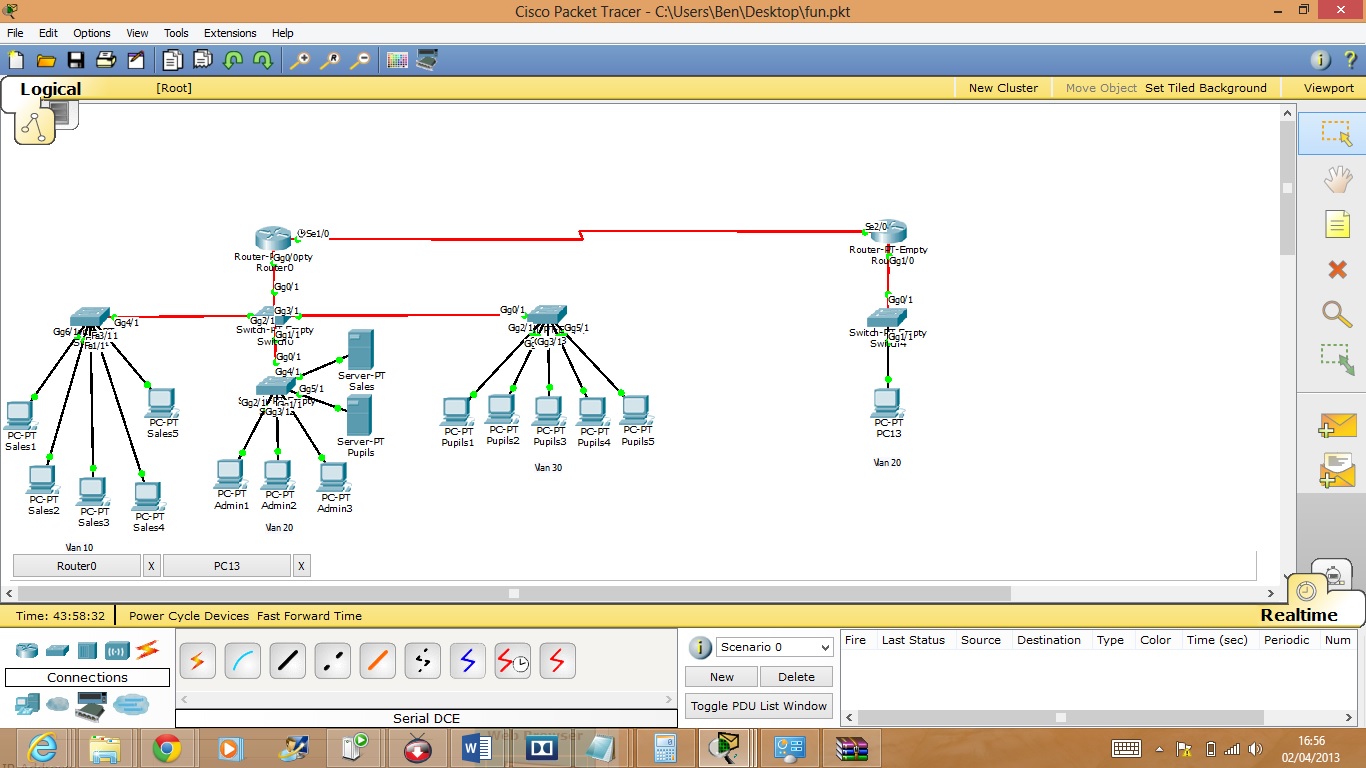
I've attached both the packet tracer and the topology jpeg. It is VLAN 20 that I am attempting to share, my goal is that PC13 on VLAN 20 (standalone) should be able to request an IP from Router 0 (which is DHCP server) as well as full communication between the other hosts on VLAN 20.
Thanks in advance.
Solved! Go to Solution.
- Labels:
-
LAN Switching
Accepted Solutions
- Mark as New
- Bookmark
- Subscribe
- Mute
- Subscribe to RSS Feed
- Permalink
- Report Inappropriate Content
04-02-2013 12:52 PM
Hi Ben,
In principle this is not possible between 2 routers. Packet tracer does not support this type of thing between routers - as Gregory mentioned you could use L2TP which is not supported in packet tracer or other enhanced protocols. You cant use the same ip address range i.e. 192.168.3.0 network on both sides without a switch / switches catering to carry the frames across to the other side.
I had a go at your lab - was great fun! I have attached my version in this post.
I had the same vlan at both sides, BUT:
one side had the 192.168.3.0 range - on vlan 20 but inaccessible from the other side, because there is no layer 2 connectivity there.
the other side had 20.20.20.0 range - same again, on vlan 20 but there is nothing to cary the frames across - hence different IP subnet
The things I changed were:
- removed servers (not sure what purpose they were serving - maybe it was for DHCP?)
- changed ospf between R0 and R1 for adjacency on the 1.1.1.0/30 network
- setup new dhcp pools on R0 192.168's and on R1 20.20.20.0's
- vlan 20 exists in both places but with different IP schemes
- everything is able to ping everything else.
- changed config on switches so they are trunking relevant vlans (this wasnt the case with your example)
- some trunk configuration on switches and sub interfaces.
R0 on the left:
ip dhcp excluded-address 192.168.2.1 192.168.2.100
ip dhcp excluded-address 192.168.3.1 192.168.3.100
ip dhcp excluded-address 192.168.4.1 192.168.4.100
!
ip dhcp pool SALES
network 192.168.2.0 255.255.255.0
default-router 192.168.2.1
ip dhcp pool ADMIN
network 192.168.3.0 255.255.255.0
default-router 192.168.3.1
ip dhcp pool PUPILS
network 192.168.4.0 255.255.255.0
default-router 192.168.4.1
!
interface GigabitEthernet0/0
no ip address
!
interface GigabitEthernet0/0.10
encapsulation dot1Q 10
ip address 192.168.2.1 255.255.255.0
!
interface GigabitEthernet0/0.20
encapsulation dot1Q 20
ip address 192.168.3.1 255.255.255.0
!
interface GigabitEthernet0/0.30
encapsulation dot1Q 30
ip address 192.168.4.1 255.255.255.0
!
interface GigabitEthernet1/0
ip address 1.1.1.1 255.255.255.252
!
router ospf 1
log-adjacency-changes
network 1.1.1.1 0.0.0.0 area 0
network 192.168.0.0 0.0.255.255 area 0
R1 on the right hand side:
ip dhcp excluded-address 20.20.20.1 20.20.20.100
!
ip dhcp pool VLAN_20
network 20.20.20.0 255.255.255.0
default-router 20.20.20.1
!
!
interface GigabitEthernet1/0
no ip address
!
interface GigabitEthernet1/0.20
encapsulation dot1Q 20
ip address 20.20.20.1 255.255.255.0
!
interface GigabitEthernet2/0
ip address 1.1.1.2 255.255.255.252
!
router ospf 1
log-adjacency-changes
network 1.1.1.2 0.0.0.0 area 0
network 20.20.20.1 0.0.0.0 area 0
Hope this has some benefit for us
Please rate useful posts and remember to mark any solved questions as answered. Thank you.
- Mark as New
- Bookmark
- Subscribe
- Mute
- Subscribe to RSS Feed
- Permalink
- Report Inappropriate Content
04-02-2013 11:01 AM
From what I see in your diagram, it looks like you are attempting to to use the same subnet off of two different routers without layer 2 connectivity between the two of the. The only way you could do something like that would be if you setup a layer 2 tunnel between the sites.
- Mark as New
- Bookmark
- Subscribe
- Mute
- Subscribe to RSS Feed
- Permalink
- Report Inappropriate Content
04-02-2013 02:49 PM
Hello
You can try ATOM connection.if your router supports it.
Router 1
ip cef
int x/x ( facing router 2)
mpls ip
mpls ldp router-id lo0
int y/y ( facing lan)
xconnect y.y.y.y 12 encap mpls
Router 2
ip cef
int x/x ( facing router 1)
mpls ip
mpls ldp router-id lo0
int y/y ( facing lan)
xconnect x.x.x.x 12 encap mpls
please note the loopback interfaces on the routers require reachability
.
res
Paul
Please don't forget to rate any posts that have been helpful.
Thanks.
Please rate and mark as an accepted solution if you have found any of the information provided useful.
This then could assist others on these forums to find a valuable answer and broadens the community’s global network.
Kind Regards
Paul
- Mark as New
- Bookmark
- Subscribe
- Mute
- Subscribe to RSS Feed
- Permalink
- Report Inappropriate Content
04-02-2013 04:15 PM
Can you expand on this please
Thanks
- Mark as New
- Bookmark
- Subscribe
- Mute
- Subscribe to RSS Feed
- Permalink
- Report Inappropriate Content
04-03-2013 12:48 AM
Hello Ben, ATOM stands for Any Transport over MPLS. Its a solution to transport layer 2 over an IP/MPLS backbone. However, its not supported in packet tracer either. It's very limited in that aspect. More commonly used with large service providers.
I have provided a white paper link on AToM below:
http://www.cisco.com/warp/public/cc/so/neso/vpn/unvpnst/atomf_wp.htm#wp34608
Hope this helps.
Please rate useful posts and remember to mark any solved questions as answered. Thank you.
- Mark as New
- Bookmark
- Subscribe
- Mute
- Subscribe to RSS Feed
- Permalink
- Report Inappropriate Content
04-02-2013 12:52 PM
Hi Ben,
In principle this is not possible between 2 routers. Packet tracer does not support this type of thing between routers - as Gregory mentioned you could use L2TP which is not supported in packet tracer or other enhanced protocols. You cant use the same ip address range i.e. 192.168.3.0 network on both sides without a switch / switches catering to carry the frames across to the other side.
I had a go at your lab - was great fun! I have attached my version in this post.
I had the same vlan at both sides, BUT:
one side had the 192.168.3.0 range - on vlan 20 but inaccessible from the other side, because there is no layer 2 connectivity there.
the other side had 20.20.20.0 range - same again, on vlan 20 but there is nothing to cary the frames across - hence different IP subnet
The things I changed were:
- removed servers (not sure what purpose they were serving - maybe it was for DHCP?)
- changed ospf between R0 and R1 for adjacency on the 1.1.1.0/30 network
- setup new dhcp pools on R0 192.168's and on R1 20.20.20.0's
- vlan 20 exists in both places but with different IP schemes
- everything is able to ping everything else.
- changed config on switches so they are trunking relevant vlans (this wasnt the case with your example)
- some trunk configuration on switches and sub interfaces.
R0 on the left:
ip dhcp excluded-address 192.168.2.1 192.168.2.100
ip dhcp excluded-address 192.168.3.1 192.168.3.100
ip dhcp excluded-address 192.168.4.1 192.168.4.100
!
ip dhcp pool SALES
network 192.168.2.0 255.255.255.0
default-router 192.168.2.1
ip dhcp pool ADMIN
network 192.168.3.0 255.255.255.0
default-router 192.168.3.1
ip dhcp pool PUPILS
network 192.168.4.0 255.255.255.0
default-router 192.168.4.1
!
interface GigabitEthernet0/0
no ip address
!
interface GigabitEthernet0/0.10
encapsulation dot1Q 10
ip address 192.168.2.1 255.255.255.0
!
interface GigabitEthernet0/0.20
encapsulation dot1Q 20
ip address 192.168.3.1 255.255.255.0
!
interface GigabitEthernet0/0.30
encapsulation dot1Q 30
ip address 192.168.4.1 255.255.255.0
!
interface GigabitEthernet1/0
ip address 1.1.1.1 255.255.255.252
!
router ospf 1
log-adjacency-changes
network 1.1.1.1 0.0.0.0 area 0
network 192.168.0.0 0.0.255.255 area 0
R1 on the right hand side:
ip dhcp excluded-address 20.20.20.1 20.20.20.100
!
ip dhcp pool VLAN_20
network 20.20.20.0 255.255.255.0
default-router 20.20.20.1
!
!
interface GigabitEthernet1/0
no ip address
!
interface GigabitEthernet1/0.20
encapsulation dot1Q 20
ip address 20.20.20.1 255.255.255.0
!
interface GigabitEthernet2/0
ip address 1.1.1.2 255.255.255.252
!
router ospf 1
log-adjacency-changes
network 1.1.1.2 0.0.0.0 area 0
network 20.20.20.1 0.0.0.0 area 0
Hope this has some benefit for us
Please rate useful posts and remember to mark any solved questions as answered. Thank you.
Find answers to your questions by entering keywords or phrases in the Search bar above. New here? Use these resources to familiarize yourself with the community:
