- Cisco Community
- Technology and Support
- Service Providers
- Service Providers Knowledge Base
- ASR9000/XR: Load-balancing architecture and characteristics
- Subscribe to RSS Feed
- Mark as New
- Mark as Read
- Bookmark
- Subscribe
- Printer Friendly Page
- Report Inappropriate Content
- Subscribe to RSS Feed
- Mark as New
- Mark as Read
- Bookmark
- Subscribe
- Printer Friendly Page
- Report Inappropriate Content
on
08-28-2012
07:08 AM
- edited on
11-22-2022
08:23 AM
by
nkarpysh
![]()

")
Introduction
In this document it is discussed how the ASR9000 decides how to take multiple paths when it can load-balance. This includes IPv4, IPv6 and both ECMP and Bundle/LAG/Etherchannel scenarios in both L2 and L3 environments
Core Issue
The load-balancing architecture of the ASR9000 might be a bit complex due to the 2 stage forwarding the platform has. In this article the various scenarios should explain how a load-balancing decision is made so you can architect your network around it.
In this document it is assumed that you are running XR 4.1 at minimum (the XR 3.9.X will not be discussed) and where applicable XR42 enhancements are alerted.
Load-balancing Architecture and Characteristics
Characteristics
ASR9000 has the following load-balancing characteristics:
- ECMP:
- Non recursive or IGP paths : 32-way
- Recursive or BGP paths:
- 8-way for Trident
- 32 way for Typhoon
- 64 way Typhoon in XR 5.1+
- 64 way Tomahawk XR 5.3+ (Tomahawk only supported in XR 5.3.0 onwards)
- Bundle:
- 64 members per bundle
The way they tie together is shown in this simplified L3 forwarding model:
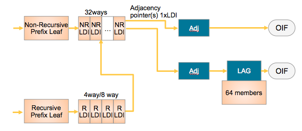
NRLDI = Non Recursive Load Distribution Index
RLDI = Recursive Load Distribution Index
ADJ = Adjancency (forwarding information)
LAG = Link Aggregation, eg Etherchannel or Bundle-Ether interface
OIF = Outgoing InterFace, eg a physical interface like G0/0/0/0 or Te0/1/0/3
What this picture shows you is that a Recursive BGP route can have 8 different paths, pointing to 32 potential IGP ways to get to that BGP next hop, and EACH of those 32 IGP paths can be a bundle which could consist of 64 members each!
Architecture
The architecture of the ASR9000 load-balancing implementation surrounds around the fact that the load-balancing decision is made on the INGRESS linecard.
This ensures that we ONLY send the traffic to that LC, path or member that is actually going to forward the traffic.
The following picture shows that:
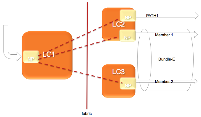
In this diagram, let's assume there are 2 paths via the PATH-1 on LC2 and a second path via a Bundle with 2 members on different linecards.
(note this is a bit extraordinary considering that equal cost paths can't be mathematically created by a 2 member bundle and a single physical interface)
The Ingress NPU on the LC1 determines based on the hash computation that PATH1 is going to forward the traffic, then traffic is sent to LC2 only.
If the ingress NPU determines that PATH2 is to be chosen, the bundle-ether, then the LAG (link aggregation) selector points directly to the member and traffic is only sent to the NP on that linecard of that member that is going to forward the traffic.
Based on the forwarding achitecture you can see that the adj points to a bundle which can have multiple members.
Allowing this model, when there are lag table udpates (members appearing/disappearing) do NOT require a FIB update at all!!!
What is a HASH and how is it computed
In order to determine which path (ECMP) or member (LAG) to choose, the system computes a hash. Certain bits out of this hash are used to identify member or path to be taken.
- Pre 4.0.x Trident used a folded XOR methodology resulting in an 8 bit hash from which bits were selected
- Post 4.0.x Trident uses a checksum based calculation resulting in a 16 bit hash value
- Post 4.2.x Trident uses a checksum based calculation resulting in a 32 bit hash value
- Typhoon 4.2.0 uses a CRC based calculation of the L3/L4 info and computes a 32 bit hash
8-way recursive means that we are using 3 bits out of that hash result
32-way non recursive means that we are using 5 bits
64 members means that we are looking at 6 bits out of that hash result
It is system defined, by load-balancing type (recursive, non-recursive or bundle member selection) which bits we are looking at for the load-balancing decision.
Fields used in ECMP HASH
What is fed into the HASH depends on the scenario:
| Incoming Traffic Type | Load-balancing Parameters |
|---|---|
| IPv4 |
Source IP, Destination IP, Source port (TCP/UDP only), Destination port (TCP/UDP only), Router ID |
| IPv6 |
Source IP, Destination IP, Source port (TCP/UDP only), Destination port (TCP/UDP only), Router ID |
| MPLS - IP Payload, with < 4 labels |
Source IP, Destination IP, Source port (TCP/UDP only), Destination port (TCP/UDP only), Router ID |
|
From 6.2.3 onwards, for Tomahawk + later ASR9K LCs: MPLS - IP Payload, with < 8 labels |
Source IP, Destination IP, Source port (TCP/UDP only), Destination port (TCP/UDP only), Router ID Typhoon LCs retain the original behaviour of supporting IP hashing for only up to 4 labels.
|
|
MPLS - IP Payload, with > 9 labels |
If 9 or more labels are present, MPLS hashing will be performed on labels 3, 4, and 5 (labels 7, 8, and 9 from 7.1.2 onwards). Typhoon LCs retain the original behaviour of supporting IP hashing for only up to 4 labels. |
| - IP Payload, with > 4 labels |
4th MPLS Label (or Inner most) and Router ID |
|
- Non-IP Payload |
Inner most MPLS Label and Router ID |
* Non IP Payload includes an Ethernet interworking, generally seen on Ethernet Attachment Circuits running VPLS/VPWS.
These have a construction of
EtherHeader-Mpls(next hop label)-Mpls(pseudowire label)-etherheader-InnerIP
In those scenarios the system will use the MPLS based case with non ip payload.
IP Payload in MPLS is a common case for IP based MPLS switching on LSR's whereby after the inner label an IP header is found directly.
Router ID
The router ID is a value taken from an interface address in the system in an order to attempt to provide some per node variation
This value is determined at boot time only and what the system is looking for is determined by:
sh arm router-ids
Example:
RP/0/RSP0/CPU0:A9K-BNG#show arm router-id
Tue Aug 28 11:51:50.291 EDT
Router-ID Interface
8.8.8.8 Loopback0
RP/0/RSP0/CPU0:A9K-BNG#
Bundle in L2 vs L3 scenarios
This section is specific to bundles. A bundle can either be an AC or attachment circuit, or it can be used to route over.
Depending on how the bundle ether is used, different hash field calculations may apply.
When the bundle ether interface has an IP address configured, then we follow the ECMP load-balancing scheme provided above.
When the bundle ether is used as an attachment circuit, that means it has the "l2transport" keyword associated with it and is used in an xconnect or bridge-domain configuration, by default L2 based balancing is used. That is Source and Destination MAC with Router ID.
If you have 2 routers on each end of the AC's, then the MAC's are not varying a lot, that is not at all, then you may want to revert to L3 based balancing which can be configured on the l2vpn configuration:
RP/0/RSP0/CPU0:A9K-BNG#configure
RP/0/RSP0/CPU0:A9K-BNG(config)#l2vpn
RP/0/RSP0/CPU0:A9K-BNG(config-l2vpn)#load-balancing flow ?
src-dst-ip Use source and destination IP addresses for hashing
src-dst-mac Use source and destination MAC addresses for hashing
Use case scenarios
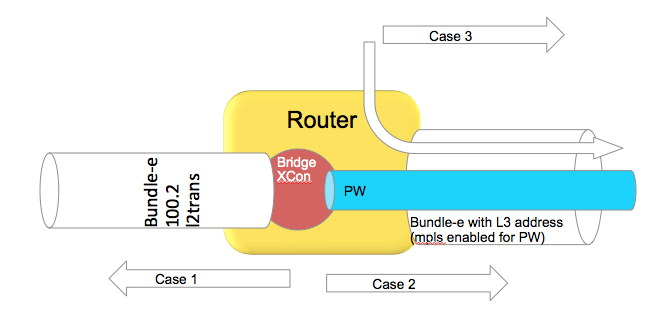
Case 1 Bundle Ether Attachment circuit (downstream)
In this case the bundle ether has a configuration similar to
interface bundle-ether 100.2 l2transport
encap dot1q 2
rewrite ingress tag pop 1 symmetric
And the associated L2VPN configuration such as:
l2vpn
bridge group BG
bridge-domain BD
interface bundle-e100.2
In the downstream direction by default we are load-balancing with the L2 information, unless the load-balancing flow src-dest-ip is configured.
Case 2 Pseudowire over Bundle Ether interface (upstream)
The attachment circuit in this case doesn't really matter, whether it is bundle or single interface.
The associated configuration for this in the L2VPN is:
l2vpn
bridge group BG
bridge-domain BD
interface bundle-e100.2
vfi MY_VFI
neighbor 1.1.1.1 pw-id 2
interface bundle-ether 200
ipv4 add 192.168.1.1 255.255.255.0
router static
address-family ipv4 unicast
1.1.1.1/32 192.168.1.2
In this case neighbor 1.1.1.1 is found via routing which appens to be egress out of our bundle Ethernet interface.
This is MPLS encapped (PW) and therefore we will use MPLS based load-balancing.
Case 3 Routing through a Bundle Ether interface
In this scenario we are just routing out the bundle Ethernet interface because our ADJ tells us so (as defined by the routing).
Config:
interface bundle-ether 200
ipv4 add 200.200.1.1 255.255.255.0
show route (OSPF inter area route)
O IA 49.1.1.0/24 [110/2] via 200.200.1.2, 2w4d, Bundle-Ether200
Even if this bundle-ether is MPLS enabled and we assign a label to get to the next hop or do label swapping, in this case
the Ether header followed by MPLS header has Directly IP Behind it.
We will be able to do L3 load-balancing in that case as per chart above.
(Layer 3) Load-balancing in MPLS scenarios
As attempted to be highlighted throughout this technote the load-balacning in MPLS scenarios, whether that be based on MPLS label or IP is dependent on the inner encapsulation.
Depicted in the diagram below, we have an Ethernet frame with IP going into a pseudo wire switched through the LSR (P router) down to the remote PE.
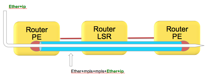
Pseudowires in this case are encapsulating the complete frame (with ether header) into mpls with an ether header for the next hop from the PE left router to the LSR in the middle.
Although the number of labels is LESS then 4. AND there is IP available, the system can't skip beyond the ether header and read the IP and therefore falls back to MPLS label based load-balancing.
How does system differentiate between an IP header after the inner most label vs non IP is explained here:
Just to recap, the MPLS header looks like this:
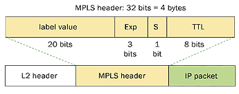
Now the important part of this picture is that this shows MPLS-IP. In the VPLS/VPWS case this "GREEN" field is likely start with Ethernet headers.
Because hardware forwarding devices are limited in the number of PPS they can handle, and this is a direct equivalent to the number of instructions that are needed to process a packet, we want to make sure we can work with a packet in the LEAST number of instructions possible.
In order to comply with that thought process, we check the first nibble following the MPLS header and if that starts with a 4 (ipv4) or a 6 (ipv6) we ASSUME that this is an IP header and we'll interpret the data following as an IP header deriving the L3 source and destination.
Now this works great in the majority scenarios, because hey let's be honest, MAC addresses for the longest time started with 00-0......
in other words not a 4 or 6 and we'd default to MPLS based balancing, something that we wanted for VPLS/VPWS.
However, these days we see mac addresses that are not starting with zero's anymore and in fact 4's or 6's are seen!
This fools the system to believe that the inner packet is IP, while it is an Ether header in reality.
There is no good way to classify an ip header with a limited number of instruction cycles that would not affect performance.
In an ideal world you'd want to use an MD5 hash and all the checks possible to make the perfect decision.
Reality is different and no one wants to pay the price for it either what it would cost to design ASICS that can do high performance without affecting the PPS rate due to a very very comprehensive check of tests.
Bottom line is that if your DMAC starts with a 4 or 6 you have a situation.
Solution
Use the MPLS control word.
Control word is negotiated end to end and inserts a special 4 bytes with zero's especially to accommodate this purpose.
The system will now read a 0 instead of a 4 or 6 and default to MPLS based balancing.
Configuration
to enable control word use the follow template:
l2vpn
pw-class CW
encapsulation mpls
control-word
!
!
xconnect group TEST
p2p TEST_PW
interface GigabitEthernet0/0/0/0
neighbor 1.1.1.1 pw-id 100
pw-class CW
!
!
!
!
Alternative solutions: Fat Pseudowire
Since you might have little control over the inner label, the PW label, and you probably want to ensure some sort of load-balancing, especially on P routers that have no knowledge over the offered service or mpls packets it transports another solution is available known as FAT Pseudowire.
FAT PW inserts a "flow label" whereby the label has a value that is computed like a hash to provide some hop by hop variation and more granular load-balancing. Special care is taken into consideration that there is variation (based on the l2vpn command, see below) and that no reserved values are generated and also don't collide with allocated label values.
Fat PW is supported starting XR 4.2.1 on both Trident and Typhoon based linecards. From 6.5.1 onward we support FAT label over PWHE.
Packet transformation with a Flow Label

Configuration of FAT Pseudowire
The following is configuration example :
l2vpn
load-balancing flow src-dst-ip
pw-class test
encapsulation mpls
load-balancing
flow-label both static
!
!
You can also affect the way that the flow label is computed:
Under L2VPN configuration, use the “load-balancing flow” configuration command to determine how the flow label is generated:
l2vpn
load-balancing flow src-dst-mac
This is the default configuration, and will cause the NP to build the flow label from the source and destination MAC addresses in each frame.
l2vpn
load-balancing flow src-dst-ip
This is the recommended configuration, and will cause the NP to build the flow label from the source and destination IP addresses in each frame.
FAT Pseudowire TLV
Flow Aware Label (FAT) PW signalled sub-tlv id is currently carrying value 0x11 as specified originally in draft draft-ietf-pwe3-fat-pw. This value has been recently corrected in the draft and should be 0x17. Value 0x17 is the flow label sub-TLV identifier assigned by IANA.
When Inter operating between XR versions 4.3.1 and earlier, with XR version 4.3.2 and later. All XR releases 4.3.1 and prior that support FAT
PW will default to value 0x11. All XR releases 4.3.2 and later default to value 0x17.
Solution:
Use the following config on XR version 4.3.2 and later to configure the sub-tlv id
pw-class <pw-name>
encapsulation mpls
load-balancing
flow-label both
flow-label code 17
NOTE: Got a lot of questions regarding the confusion about the statement of 0x11 to 0x17 change (as driven by IANA) and the config requirement for number 17 in this example.
The crux is that the flow label code is configured DECIMAL, and the IANA/DRAFT numbers mentioned are HEX.
So 0x11, the old value is 17 decimal, which indeed is very similar to 0x17 which is the new IANA assigned number. Very annoying, thank IANA
(or we could have made the knob in hex I guess )
Loadbalancing and priority configurations
In the case of VPWS or VPLS, at the ingress PE side, it’s possible to change the load-balance upstream to MPLS Core in three different ways:
1. At the L2VPN sub-configuration mode with “load-balancing flow” command with the following options:
RP/0/RSP1/CPU0:ASR9000(config-l2vpn)# load-balancing flow ?
src-dst-ip
src-dst-mac [default]
2. At the pw-class sub-configuration mode with “load-balancing” command with the following options:
RP/0/RSP1/CPU0:ASR9000(config-l2vpn-pwc-mpls-load-bal)#?
flow-label [see FAT Pseudowire section]
pw-label [per-VC load balance]
3. At the Bundle interface sub-configuration mode with “bundle load-balancing hash” command with the following options:
RP/0/RSP1/CPU0:ASR9000(config-if)#bundle load-balancing hash ? [For default, see previous sections]
dst-ip
src-ip
It’s important to not only understand these commands but also that: 1 is weaker than 2 which is weaker than 3.
Example:
l2vpn
load-balancing flow src-dst-ip
pw-class FAT
encapsulation mpls
control-word
transport-mode ethernet
load-balancing
pw-label
flow-label both static
interface Bundle-Ether1
(...)
bundle load-balancing hash dst-ip
Because of the priorities, on the egress side of the ingress PE (to the MPLS Core), we will do per-dst-ip load-balance (3).
If the bundle-specific configuration is removed, we will do per-VC load-balance (2).
If the pw-class load-balance configuration is removed, we will do per-src-dst-ip load-balance (1).
with thanks to Bruno Oliveira for this priority section
P2MP MPLS TE Tunnels
Only one bundle member will be selected to forward traffic on the P2MP MPLS TE mid-point node.
Possible alternatives that would achieve better load balancing are: a) increase the number of tunnels or b) switch to mLDP.
IPv6
Pre 4.2.0 releases, for the ipv6 hash calculation we only use the last 64 bits of the address to fold and feed that into the hash, this including the regular routerID and L4 info.
In 4.2.0 we made some further enhancements that the full IPv6 Addr is taken into consideration with L4 and router ID.
Determining load-balancing
You can determine the load-balancing on the router by using the following commands
L3/ECMP
For IP :
RP/0/RSP0/CPU0:A9K-BNG#show cef exact-route 1.1.1.1 2.2.2.2 protocol udp ?
source-port Set source port
You have the ability to only specify L3 info, or include L4 info by protocol with source and destination ports.
It is important to understand that the 9k does FLOW based hashing, that is, all packets belonging to the same flow will take the same path.
If one flow is more active or requires more bandwidth then another flow, path utilization may not be a perfect equal spread.
UNLESS you provide enough variation in L3/L4 randomness, this problem can't be alleviated and is generally seen in lab tests due the limited number of flows.
For MPLS based hashing :
RP/0/RSP0/CPU0:A9K-BNG#sh mpls forwarding exact-route label 1234 bottom-label 16000 ... location 0/1/cpu0
This command gives us the output interface chosen as a result of hashing with mpls label 16000. The bottom-label (in this case '16000') is either the VC label (in case of PW L2 traffic) or the bottom label of mpls stack (in case of mpls encapped L3 traffic with more than 4 labels). Please note that for regular mpls packets (with <= 4 labels) encapsulating an L3 packet, only IP based hashing is performed on the underlying IP packet.
Also note that the mpls hash algorithm is different for trident and typhoon. The varied the label is the better is the distribution. However, in case of trident there is a known behavior of mpls hash on bundle interfaces. If a bundle interface has an even number of member links, the mpls hash would cause only half of these links to be utlized. To get around this, you may have to configure "cef load-balancing adjust 3" command on the router. Or use odd number of member links within the bundle interface. Note that this limitation applies only to trident line cards and not typhoon.
Bundle member selection
RP/0/RSP0/CPU0:A9K-BNG#bundle-hash bundle-e 100 loc 0/0/cPU0
Calculate Bundle-Hash for L2 or L3 or sub-int based: 2/3/4 [3]: 3
Enter traffic type (1.IPv4-inbound, 2.MPLS-inbound, 3:IPv6-inbound): [1]: 1
Single SA/DA pair or range: S/R [S]:
Enter source IPv4 address [255.255.255.255]:
Enter destination IPv4 address [255.255.255.255]:
Compute destination address set for all members? [y/n]: y
Enter subnet prefix for destination address set: [32]:
Enter bundle IPv4 address [255.255.255.255]:
Enter L4 protocol ID. (Enter 0 to skip L4 data) [0]:
Invalid protocol. L4 data skipped.
Link hashed [hash_val:1] to is GigabitEthernet0/0/0/19 LON 1 ifh 0x4000580
The hash type L2 or L3 depends on whether you are using the bundle Ethernet interface as an Attachment Circuit in a Bridgedomain or VPWS crossconnect, or whether the bundle ether is used to route over (eg has an IP address configured).
Polarization
Polarization pertains mostly to ECMP scenarios and is the effect of routers in a chain making the same load-balancing decision.
The following picture tries to explain that.
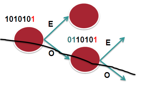
In this scenario we assume 2 bucket, 1 bit on a 7 bit hash result. Let's say that in this case we only look at bit-0. So it becomes an "EVEN" or "ODD" type decision. The routers in the chain have access to the same L3 and L4 fields, the only varying factor between them is the routerID.
In the case that we have RID's that are similar or close (which is not uncommon), the system may not provide enough variation in the hash result which eventually leads to subsequent routers to compute the same hash and therefor polarize to a "Southern" (in this example above) or "Northern" path.
In XR 4.2.1 via a SMU or in XR 4.2.3 in the baseline code, we provide a knob that allows for shifting the hash result. By choosing a different "shift" value per node, we can make the system look at a different bit (for this example), or bits.
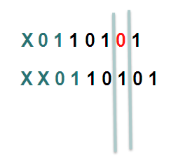
In this example the first line shifts the hash by 1, the second one shifts it by 2.
Considering that we have more buckets in the real implementation and more bits that we look at, the member or path selection can alter significantly based on the same hash but with the shifting, which is what we ultimately want.
HASH result Shifting
- Trident allows for a shift of maximum of 4 (performance reasons)
- Typhoon allows for a shift of maximum of 32.
Command
cef load-balancing algorithm adjust <value>
The command allows for values larger then 4 on Trident, if you configure values large then 4 for Trident, you will effectively use a modulo, resulting in the fact that shift of 1 is the same as a shift of 5
Fragmentation and Load-balancing
When the system detects fragmented packets, it will no longer use L4 information. The reason for that is that if L4 info were to be used, and subsequent fragments don't contain the L4 info anymore (have L3 header only!) the initial fragment and subsequent fragments produce a different hash result and potentially can take different paths resulting in out of order.
Regardless of release, regardless of hardware (ASR9K or CRS), when fragmentation is detected we only use L3 information for the hash computation.
Hashing updates
- Starting release 6.4.2, when an layer 2 interface (EFP) receives mpls encapped ip packets, the hashing algorithm if configured for src-dest-ip will pick up ip from ingress packet to create a hash. Before 6.4.2 the Hash would be based on MAC.
- Starting XR 6.5, layer 2 interfaces receiving GTP encapsulated packets will automatically pick up the TEID to generate a hash when src-dest-ip is configured.
Related Information
Xander Thuijs, CCIE #6775
Sr Tech Lead ASR9000
- Mark as Read
- Mark as New
- Bookmark
- Permalink
- Report Inappropriate Content
It almost makes me believe that there is something wrong with the member! is it distributing?
check the show bundle bundle-e <number> and show lacp bundle-e <number> to see if it is properly enabled in the bundle, because it looks like the control plane doesnt see that other member active...
The HASH algorithm is a crc calculation based on L3 and L4 info (if proto is TCP or UDP) and adding the routerID (to get some per node variation). The different schemes, ECMP, bundle etc look at different bits for the bucket assignemtns.
the buckets there are, are divided over the members (bundle) or paths (ecmp) as available.
There is no inclusion of actual bandwidth (we require currently equal cost paths or members), although there is UCMP available also (see related article on that)
regards
xander
- Mark as Read
- Mark as New
- Bookmark
- Permalink
- Report Inappropriate Content
Yep it is! If I shut down the interface used now the traffic goes over the other one with no problems -
RP/0/RSP0/CPU0:ASR9K_P1-2#show bundle bundle-ether 2
Sat Oct 5 18:29:57.757 EEST
Bundle-Ether2
Status: Up
Local links <active/standby/configured>: 2 / 0 / 2
Local bandwidth <effective/available>: 20000000 (20000000) kbps
MAC address (source): d867.d95f.5a6a (Chassis pool)
Inter-chassis link: No
Minimum active links / bandwidth: 1 / 1 kbps
Maximum active links: 64
Wait while timer: 2000 ms
Load balancing: Default
LACP: Operational
Flap suppression timer: Off
Cisco extensions: Disabled
mLACP: Not configured
IPv4 BFD: Not configured
Port Device State Port ID B/W, kbps
-------------------- --------------- ----------- -------------- ----------
Te0/0/0/0 Local Active 0x8000, 0x0001 10000000
Link is Active
Te0/0/0/1 Local Active 0x8000, 0x0002 10000000
Link is Active
RP/0/RSP0/CPU0:ASR9K_P1-2#show lacp bundle-ether 2
Sat Oct 5 18:30:06.267 EEST
State: a - Port is marked as Aggregatable.
s - Port is Synchronized with peer.
c - Port is marked as Collecting.
d - Port is marked as Distributing.
A - Device is in Active mode.
F - Device requests PDUs from the peer at fast rate.
D - Port is using default values for partner information.
E - Information about partner has expired.
Bundle-Ether2
Port (rate) State Port ID Key System ID
-------------------- -------- ------------- ------ ------------------------
Local
Te0/0/0/0 1s ascdAF-- 0x8000,0x0001 0x0002 0x8000,d8-67-d9-5f-5a-6c
Partner 1s ascdAF-- 0x8000,0x0001 0x0001 0x8000,b4-a4-e3-93-44-5c
Te0/0/0/1 1s ascdAF-- 0x8000,0x0002 0x0002 0x8000,d8-67-d9-5f-5a-6c
Partner 1s ascdAF-- 0x8000,0x0002 0x0001 0x8000,b4-a4-e3-93-44-5c
Port Receive Period Selection Mux A Churn P Churn
-------------------- ---------- ------ ---------- --------- ------- -------
Local
Te0/0/0/0 Current Fast Selected Distrib None None
Te0/0/0/1 Current Fast Selected Distrib None None
RP/0/RSP0/CPU0:ASR9K_P1-2#
- Mark as Read
- Mark as New
- Bookmark
- Permalink
- Report Inappropriate Content
thanks again for all these tests and verifications.
ok, file a tac case please and collect a show tech bundle along with the info that we have collected so far.
To see if we can restore this behavior, you can try to do a proc restart on the bundle manager and removing and reconfiguring the bundle ether that is currently at fault.
there is a bug that is for sure, this detail and the show tech will help for a post mortem in case either of the 2 approaches "fixes" this current issue.
regards
xander
- Mark as Read
- Mark as New
- Bookmark
- Permalink
- Report Inappropriate Content
Hi Alexander,
Great tech node(BRKSPG2904) i watched the complete video and was able to get many new thinks. Keep the good work!
Now back to my topic with Trident not balancing when we have MPLS+NonIP. As adviced by TAC we tried -
cef load-balancing algorithm adjust <value> i used 1 and this amaizingly made it work !!!
Now you can imagine my frostration when the TAC engineer said that this is normal and the issue was polarization.
I was thinking a lot on this subject and my conclusion is as follows please correct me if i am wrong -
Hash result shifting should affect the balancing in case we are making the same decision on many nodes in a chain !!! i.e all taking the left link for example
My node was not balancing at all so shitfting the result with one should not make a difference.
They only think that could made it is if hash shifting was changing on a round roubin fashion - for examlpe first flow - shift, second one don't shift etc... but then we can't gurantee that all packets from a specific flow will take the same interface out - not good idea. Now the only other think that could be the reason for the node not to balance is if the platform by default was looking at a bit or bits not changing at all for all flows (for example udp port number) thoes not balancing before we shift the hash result forcing it to use bits in the hash results that are actually chaning. If this is the case then maybe this should be fixed ?
BR
B.
- Mark as Read
- Mark as New
- Bookmark
- Permalink
- Report Inappropriate Content
I didn't realize that recording was posted also , good to hear you enjoyed it!
And also nice to see that your issue is resolved.
The general use case for the hash shift command is to prevent polarization in case you have chains of devices that use the same hash calculation approach. The hash shift makes the loadbalancer look at different bits (still the same position, but since they are shifted the bit values are "hopefully" different), if we use "random shifts" on different devices we can try to balance more effectively.
It seems like your flow distribution has an entropy variation that didnt produce enough randomness and resulted in polarization. I can see why the hash shift resolves it, but at the same time I am surprised it was necessary in this scenario already.
xander
- Mark as Read
- Mark as New
- Bookmark
- Permalink
- Report Inappropriate Content
Hi Alexander,
I see that you updated the document but unfortunatelly the document comparison says - "
The document body was too large to do a version comparison
"
Can you just briefly note what was the change ? THe document is really to big have it eye spoted
BR
Bozhidar
- Mark as Read
- Mark as New
- Bookmark
- Permalink
- Report Inappropriate Content
hi bhozidar, ah thanks for noticing! that is correct, I added the section on:
cheers
xander
- Mark as Read
- Mark as New
- Bookmark
- Permalink
- Report Inappropriate Content
10x
cheers
b.
- Mark as Read
- Mark as New
- Bookmark
- Permalink
- Report Inappropriate Content
Hi Alexander,
I have another tricky setup with loadbalancing.
I have a NG-MVPN with P2MP-TE with BGP-AD and BGP c-mcast routing used for IP TV. Basically what i see is that on the edge router from where the muticast traffic is sourced (MTE tunnel headend) the mcast traffic is balanced on the bundle interface towards the core. The problem is that on the next hop - i.e the core to core bundle interface the traffic is not balanced anymore. Now the question is - Is this normal and expected behaviour or I need to add something to my configuraion in order to start balancing the multicast traffic ?
I have tried the bundle-hash comand but looks like it;s not accepting mcast address for a destination -
Enter destination IPv4 address [255.255.255.255]: 236.5.14.24
Invalid destination address
Another? [y]: n
BR
Bozhidar
- Mark as Read
- Mark as New
- Bookmark
- Permalink
- Report Inappropriate Content
hi Bozhidar,
have you configured for the right multicast loadbalancing configuration on the router to use the source/next-hop and or group?
also it may help using hte hash shift command which affects the bundle hash selection also.
cheers!
xander
- Mark as Read
- Mark as New
- Bookmark
- Permalink
- Report Inappropriate Content
Guys you are getting faster than TAC ;o)
I received your update almost 12 hours ahead of the TAC reply to my case reagading absolutely the same question -
"
P2MP MPLS TE Tunnels
Only one bundle member will be selected to forward traffic on the P2MP MPLS TE mid-point node.
Possible alternatives that would achieve better load balancing are: a) increase the number of tunnels or b) switch to mLDP.
"
Keep up the good work.
BR
B.
- Mark as Read
- Mark as New
- Bookmark
- Permalink
- Report Inappropriate Content
Hello,
Great article, very useful. Thanks for writing it.
Just one questions. If I was to trace an actual path for a pseudowire over MPLS using flow labels how would I go about doing it? On the PE can do I just use the sh mpls forwarding exact-route label ...and include the payload ipv4 field (src/dst)? Will that command show me the correct outgoing intraface by calcualting the flow label?
How about on the P routers. Woudln't I need to know the flow label for that as well? How could I generate it in the CLI?
Thank you.
- Mark as Read
- Mark as New
- Bookmark
- Permalink
- Report Inappropriate Content
Hi tomek0001, thanks for the comment!
the flow label is computed at the PE edge devices, so on P routers they just look at the inner label (if they see a 0 after the inner label, or that is non 4 or non 6), so you could use the show mpls forwarding command by providing the next hop label and bottom label that is used for loadbalancing.
The flow label is computed based on L3 and potentially L4 info fed by the RID also, and on the PE edge device that show mpls forwarding exact route can be used there also by providing a "self computed" flow label, or you can provide IP info also, but that doesnt necesarily mean/reflect the computed flow label.
a traceroute for MPLS would not take flow label into consideration as far as I am aware, so other then providing an actual traffic stream there is little that would reflect the "reality".
You can do a multipath traceroute to verify and identify multipaths in mpls, but there are no easy tools available that would allow you to follow a path based on flow labels.
regards
xander
- Mark as Read
- Mark as New
- Bookmark
- Permalink
- Report Inappropriate Content
Thank you for your response. I just wanted to clarify my questions little more and expand on it.
1. One thing I found confusing in the article is the requirement of the control word. Do you still require it when using flow labels? When you enable flow labels, is the detection of IPv4/IPv6 header disabled? So even if you are using flow labels with mac addresses that start with 4 or 6, routers will only look at the bottom of the stack label and won't try to detect if it's an IPv4 header? If that's not the case do you still have to enable control word when using flow labels?
2. I'm currently troubleshooting a situation with ECMP and Bundle interfaces that are causing out of order delivery. Outside of the issue of not using using control word and having mac addresses start with 4/6, have you seen anything that could cause out of order delivery with pseudo-wires, IP load sharing or bundle hashing?
3. I understand the traceroute would not work, but I was looking for a manual hop by hop way to tracing one particular flow encapsulated in a pseudorwire. This is where my original question was mostly about. I was trying to use the command "sh mpls forwarding exact-route label 16004 bottom-label ?" both on Ps and PEs, but in this case how do I know what the bottom label is...i.e. the flow label value that's calculated? Once I know it, I should be able to go manually from each MPLS device and find out the exact path for a particular pseudowire encapsulating a particular src/dst ipv4 packet.
Thank you again for your help.
Tom
- Mark as Read
- Mark as New
- Bookmark
- Permalink
- Report Inappropriate Content
hi tom,
CW and flow label solve different issues:
CW is used to prevent a device from interpreting a 4 or 6 afer the inner label as IP
Flow label is used to provide a new entropie label to do loadbalancing on as opposed to the next inner one (which is usually PE next hop or PW label and rather static for a point to point connection).
If the inner payload is truly IP, then the CW makes the device no longer interpret payload as IP hence starts
to LB on the PW label. Flow label provides then that granularity of giving the option of a more per flow based balancing.
the out of order delivery i have seen happening mainly because of that dmac sarting with 4 or 6 in PW's.
the bottom label is the PW label. it could be visible from the pw connection or the cef rewrite string.
regards
xander
Find answers to your questions by entering keywords or phrases in the Search bar above. New here? Use these resources to familiarize yourself with the community: