- Cisco Community
- Technology and Support
- Service Providers
- Service Providers Knowledge Base
- ASR9000/XR: Local Packet Transport Services (LPTS) CoPP
- Subscribe to RSS Feed
- Mark as New
- Mark as Read
- Bookmark
- Subscribe
- Printer Friendly Page
- Report Inappropriate Content
- Subscribe to RSS Feed
- Mark as New
- Mark as Read
- Bookmark
- Subscribe
- Printer Friendly Page
- Report Inappropriate Content
on 02-28-2012 05:58 AM
Introduction
IOS devices have the concept of control plane policing. IOS-XR doesn't use that concept but instead uses a very comprehensive and powerful Local Packet Transport Services. In this document it is explained how LPTS works and how you can work with it, monitor and verify it.
Core Issue
LPTS is the concept of reflexive ACL's, punt policers and has an "internal" FIB or iFIB that directs certain packets to various nodes. IOS-XR can handle certain traffic on the linecard (such as BFD, Netflow and ARP) and these packets are instructed by LPTS to be handled by the local CPU rather then the RSP CPU.
At the same time, there are ACL's in place that allow for instance the punting of Telnet traffic and then per host if configured so, but another component of LPTS called MPP, the Management Plane Protection.
Generally, the default values for LPTS provide the level of protection you are after. However there are some rare circumstances whereby you want to tune the values of LPTS in order to get the service levels you need. LPTS is very dynamic in nature and pierces holes into the protection system as particular items are configured.
The LPTS policers work on a per NP basis. So if the LPTS police value is set to 1000pps that means that every NP on the LC can punt with 1000pps to the RSP CPU or LC CPU. This is something to take into consideration when evaluating the A9K-8T-x cards who have 8 NPU's per LC.
Take extreme care when changing the LPTS policer values.
High level overview
From a birds eye view, LPTS looks like this:
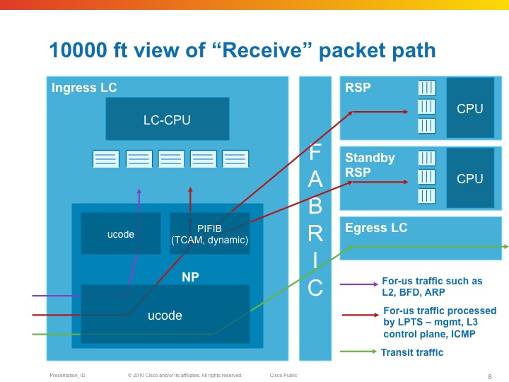
The NPU has a table that tells it where to send packet to (LC or RSP) as part of the "internal FIB" or iFIB. These packets are punted at a pre-defined rate, they can be tuned in XR release 4.x and later. Also in the TCAM which is used in the ASR9K for ACLs (amongst others), are lists that define which packets we want to allow and not. This will be discussed in the MPP section of this document.
| LPTS is composed of a (set of) dynamic ACL's (which are created as part of user configuration dynamically, or automitcally inserted as peerings establish), an internal "routing table" (iFIB) and a set of policers for different punt reasons. |
|---|
LPTS Characteristics
So for-me packets are undergoing the Pre iFIB classification and policing upon which they are directed by the iFIB, which is the second level of filtering to the destination node.
LPTS Firewalling
One of the great strenghts with LPTS is the dynamic ACL creation. This is configuration driven and no user intervention is required.
In addition to that, LPTS has different flow categories based on the state of the protocol. For instance, BGP has 3 different states:
- Unknown
- Configured
- Established
Unknown is the flow whereby we have TCP port 179 traffic, but we have no neighbor configured from that source. Policed very heavily.
Configured is the entry whereby we know the source address of the peer, but the session is not yet established (no known source port from the peer), Policed moderately.
Established is where we have all the L3 and L4 data from the session. Lightly policed.
The entries for configured is driven by the configuration of the neighbor statement under the router BGP section.
Established is dynamically inserted when the peer establishes.
You could theoretically police the unknown to a rate of zero.
Example:
Router bgp
neighbor 192.168.1.1
…
!
The following table can be seen with the output of the command:
show lpts pifib hardware entry brief loc 0/3/cpu0 | i 179
| Local | Port | Remote | Port | Rate | State |
|---|---|---|---|---|---|
| any | 179 | ANY | ANY | 100 | unknown |
| any | 179 | 192.168.1.1 | ANY | 1,000 | configured |
| 192.168.1.2 | 179 | 192.168.1.1 | 2223 | 10,000 | established |
If you use the command
RP/0/RSP0/CPU0:A9K-TOP#show lpts pifib hardware entry location 0/3/CPU0 | be 33.33.1
You can check the detailed entry of the PiFIB (policer)
Source IP : 33.33.1.1 the remote address
Is Fragment : 0 fragments allowed
Interface : any expected source interface
M/L/T/F : 0/IPv4_STACK/0/BGP-known
DestNode : 48 where the packets are sent to
DestAddr : 48
L4 Protocol : TCP
TCP flag byte : any additional security checks at TCP level
Source port : Port:179
Destination Port : 11293
Accepted/Dropped : 117866/0 packets accepted and denied
# of TCAM entries : 1 number of tcam entries burnt for this PiFIB entry
HPo/HAr/HBu/Cir : 1924676/2500pps/2500ms/2500pps
State : Entry in TCAM status of the entry
Configuring LPTS police rates
You can configure the LPTS Policers on a PiFIB bases and also the punt policers can be adjusted.
The following commands apply. Note that this is on a per linecard basis. All NPU's on that linecard will get reconfigured.
RP/0/RSP0/CPU0:A9K-BNG(config)#lpts punt police location 0/0/CPU0 protocol ?
arp ARP packets
bfd Bidirectional Forwarding Detection packets
cdp Cisco Discovery Protocol packets
cfm Connectivity Fault Management Protocol packets
cgmp Cisco Group Management Protocol packets
dhcp Dynamic Host Configuration Protocol packets
efm Ethernet in the First Mile Protocol packets
igmp-snoop Internet Group Management Protocol Snoop packets
ipiw-arp L2VPN IPIW ARP packets
ipv4 IPv4 packets
ipv6 IPv6 packets
lacp Bundle Protocol packets
mofrr Multicast-only FRR packets
mpls MPLS punt packets
mstp Multiple Spanning Tree Protocol packets
mvrp Multiple VLAN Registration Protocol packets
ppp Point-to-Point Protocol packets
pppoe Point-to-Point Protocol over Ethernet packets
rarp Reverse ARP packets
vccv Virtual Circuit Connection Verification packets
vidmon Video Monitoring packets
vidmon-flow-add Video Monitoring flow add packets
Exception packets can be reconfigured by the following command: lpts punt police location 0/0/CPU0 exception
Glean adjacency or ACL-deny packets can be tuned for instance via that command.
The PIFIB can be reconfigured via the following commands:
RP/0/RSP0/CPU0:A9K-BNG(config)#lpts pifib hardware ...
- In there you can enter the linecard you wish to specifically reconfigure
- The policer flow values
- And the TCAM entries (this is new in XR420)
- As you've seen LPTS can dynamically create "ACL" entries for dynamic firewalling and for MPP. This command limits the number of TCAM entries that LPTS can use so that space is available for other purposes such as regular ACL's, QOS matching, EFP matching etc.
LPTS static-police and police differences
The command “police” is used to check policer values, accept/drop counts for packets matching LPTS TCAM(mostly L3 packets) entries whereas “static-police” is used to check policer values.
Accept/drop counts for packets matching static punt reasons programmed in search structures (Mostly L2 and exception packets).
“policer” is for dynamic flows (like BGP, OSPF, etc protocols directed by RSP)
“static-policer” is for pseudo Static flows (like BFD, CFM directed by the LC) These are hard-coded and include Exception processing packets.
There is a CLI to change few of the exception processing as well (for e.g. ICMP unreachable)
Monitoring LPTS
LPTS is not SNMP enabled (request has been filed and is in the works, no target release defined at time of writing). Though there are very inventive ways to monitor LPTS and generate alerts. There is a TCL script that you can use with EEM in order to get some level of alerting.
Attached to this article is the script package and here is how you set it up:
event manager environment EEM_LPTS_CHECK_INTERVAL 300 event manager environment EEM_LPTS_CHECK_FLOWTYPES BGP-known * event manager environment EEM_LPTS_CHECK_LOCATIONS 0/0/CPU0 0/4/CPU0 event manager environment EEM_LPTS_CHECK_THRESHOLD 1 50% event manager directory user policy disk0:/scripts/ event manager policy lpts-threshold-alerting.tcl username scripts |
|---|
How to clear LPTS statistics
LPTS stats cannot be cleared by LPTS commands or qos counter clearing.
You can clear LPTS stats by clearing hte np controller stats:
"clear controllers np counters all location <>”
MPP: Managed Plane Protection
In the standard configuration all interfaces have access to the Telnet, SSH and SNMP daemons.
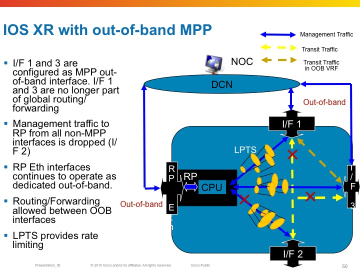
Inband vs Out of band
All linecard interfaces are designated to be inband, meaning they can transport user traffic as well as management traffic.
The mgmt interfaces on the RSP are designated out of band. This means that they can't transport user traffic but only management traffic.
Out-of-band interfaces can't "speak" to other interfaces as they are desginated for managment traffic. So eventhough there is a route in the system that would send traffic out of the mgmt interface, Fabric enabled interfaces on the LC can't
Here an example of out of band and the restrictions that it imposes on the forwarding
Configuring MPP
By default when the service is configured, there are no mpp restrictions. All interfaces are able to accept the mgmt traffic for the service you defined. For example, when the telnet server is configured, LPTS reports the following binding:
RP/0/RSP0/CPU0:A9K-BNG#show lpts bindings brief | i (any.23 )
Tue Feb 28 12:00:55.195 EDT
0/RSP0/CPU0 TCP LR IPV4 TCP default any any,23 any
This means that every for me packet with port 23 as the dest port will get serviced.
Now when configuring MPP the bindings output changes:
control-plane
management-plane
inband
interface TenGigE0/1/0/0
allow Telnet peer
address ipv4 3.3.3.3
address ipv4 5.5.5.0/28
!
!
interface GigabitEthernet0/0/0/10
allow Telnet
!
!
!
In this configuration example I am designating two interfaces as inband, so they will still be able to forward transient traffic and allow inbound telnet traffic. At the same time I allow telnet from any host on Gig0/0/0/10 and only telnet from a few peers on Te0/1/0/0.
The LPTS bindings are dynamically changed as per following output:
RP/0/RSP0/CPU0:A9K-BNG#show lpts bindings brief | i (any.23 )
Tue Feb 28 12:06:48.339 EDT
0/RSP0/CPU0 TCP LR IPV4 TCP default Gi0/0/0/10 any,23 any << Any source can access my telnet on this intf
0/RSP0/CPU0 TCP LR IPV4 TCP default Mg0/RSP0/CPU0/0 any,23 any << Dedicated inband
0/RSP0/CPU0 TCP LR IPV4 TCP default Te0/1/0/0 any,23 3.3.3.3 << /32 host access for telnet on dedicated intf
0/RSP0/CPU0 TCP LR IPV4 TCP default Te0/1/0/0 any,23 5.5.5.0/28 << Hosts from this subnet on this intf
Powerful eh!?!
We can also look at the pre internal fib (piFIB) and check the entries there:
RP/0/RSP0/CPU0:A9K-BNG#show lpts pifib hardware entry bri location 0/1/cpu0 | i (.23 )
Tue Feb 28 12:27:46.389 EDT
7 IPV4 default TCP Te0/1/0/0 LU(48) any,23 3.3.3.3,any
10 IPV4 default TCP Te0/1/0/0 LU(48) any,23 5.5.5.0/28,any
Decoding the Destnode in LPTS entries
In the example above you see the following detail: LU(48). This section explains that number and detail.
The LU means local unicast fabric. The 48 is a very interesting number.
The device that this output is taken from is an ASR9010. Which has 8 LC slots and 2 RSP slots. On both sides of the RSP's in the middle
are the 4 LC's
If I were to decode the 30 into binary it looks like this:
+---+---+---+---+---+---+---+---+
| 7 | 6 | 5 | 4 | 3 | 2 | 1 | 0 | Position
+---+---+---+---+---+---+---+---+
| 0 | 0 | 1 | 1 | 0 | 0 | 0 | 0 | Bit value for Decimal 48
+---+---+---+---+---+---+---+---+
|LC |LC |RSP|RSP|LC |LC |LC |LC | Slot position filling (note 2 left most LC's not drawn)
+---+---+---+---+---+---+---+---+
Now you can see that the 1's are in position 5 and 4, and if you look at the slot numbering of the ASR9006, you can see that these are
the RSP's!! So telnet is delivered to the RSP.
Restrictions for MPP
6) No MIB Support
Related Information
Cisco Guide to Harden Cisco IOS XR Devices
LPTS Considerations
If you can use only p2p OSPF network type
flow ospf-uc-known rate 0
flow ospf-uc-default rate 0
flow bgp-default rate 0
flow ldp-tcp-default rate 0
flow msdp-default rate 0
Xander Thuijs, CCIE #6775
Sr. Tech Lead ASR9000
- Mark as Read
- Mark as New
- Bookmark
- Permalink
- Report Inappropriate Content
I filter only drop as below:
RP/0/RSP0/CPU0:r1#sho lpts pifib hardware static-police location 0/0/CPU0
Punt Reason SID Flow Rate Burst Rate Accepted Dropped Destination
----------------------- ----------------------- --------- --------- -------------------- -------------------- -----------
IPV4MC_DO_ALL_BUT_FWD NETIO_LOW 1000 1000 2318 2147 Local
PUNT_NO_MATCH NETIO_LOW 200 200 146026275 51 Local
IPV4_TTL_ERROR NETIO_LOW 500 400 8610447 2875307 Local
PUNT_ADJ NETIO_LOW 300 200 91489353 238319 Local
MPLS_TTL_ONE_PUNT NETIO_LOW 500 400 23482 80884 Local
In my opinion, depend on the customer isn’t make sense because each customer have behavior differently. For example customer A may ping repeat 1000 size 100, customer B ping repeat 2000 size 1500. Does Cisco have any recommend? I ping from PE to CE, the result is normally. This is result from my customer:
KR#ping x.x.128.157 re 1000 size 100 data 0000
Success rate is 100 percent (1000/1000), round-trip min/avg/max = 1/1/4 ms
KR#ping x.x.128.157 re 1000 size 1500 data 0000
Success rate is 95 percent (953/1000), round-trip min/avg/max = 1/1/4 ms
Thank you very much.
- Mark as Read
- Mark as New
- Bookmark
- Permalink
- Report Inappropriate Content
Hi Xander,
I was going trough the LPTS config guide in hope to find out if it's possible to get a log message if LPTS has dropped one or more packets.
Under "show
Hmm, maybe it's possible to use SNMP for that?
- Mark as Read
- Mark as New
- Bookmark
- Permalink
- Report Inappropriate Content
hi smail, yeah the attached alerting script helps with generating some alerts on defined variables/policers from lpts. natively in xr that doesnt exist.
recently there was an snmp mib added for lpts, so yeah you can do it off box.
xander
- Mark as Read
- Mark as New
- Bookmark
- Permalink
- Report Inappropriate Content
Hi Xander,
The information provided in article is very much useful.
As per below logs, every time only below 2 interfaces got affected due to penalty and other 2 were not affected.
So wanted to check if there is any algorithm/rule to select the interfaces to be penalized or interfaces gets affected randomly.
RP/0/RSP0/CPU0:Jul 5 15:24:19.012 IST: BM-DISTRIB[1191]: %L2-BM-6-ACTIVE : GigabitEthernet0/2/0/5 is no longer Active as part of Bundle-Ether21 (Link is Expired; LACPDUs are not being received from the partner)
RP/0/RSP0/CPU0:Jul 5 15:39:18.652 IST: BM-DISTRIB[1191]: %L2-BM-6-ACTIVE : GigabitEthernet0/2/0/4 is Active as part of Bundle-Ether21
RP/0/RSP0/CPU0:Jul 5 15:39:18.655 IST: BM-DISTRIB[1191]: %L2-BM-6-ACTIVE : GigabitEthernet0/2/0/5 is Active as part of Bundle-Ether21
- Mark as Read
- Mark as New
- Bookmark
- Permalink
- Report Inappropriate Content
yeah it looks like the LACP messages are tripping the flow trap here causing your bundle members to flap. you cannot selectively enable interfaces unfortunately. one thing to do is to use lacp period long to reduce the messages.
here is some reference on that flow trap:
http://www.cisco.com/c/en/us/td/docs/routers/asr9000/software/asr9k_r5-3/bng/configuration/guide/b-bng-cg53xasr9k/b-bng-cg53xasr9k_chapter_0111.html
may want to do a tac case to file for an enhancement possibly to allowexclusion of LACP.
or also increase the flow rate allowed, this could alleviate the problem too.
xander
- Mark as Read
- Mark as New
- Bookmark
- Permalink
- Report Inappropriate Content
Thanks for the revert.
I am not willing to enable selection of interfaces to get penalized. I want to know that is there any mechanism or algorithm which selects the interfaces or can we conclude that although there are 4 interfaces in bundle, any randomly selected interfaces will get penalized.
Is there any documentation available on LPTS treatment for Excessive Bundle Protocol Flow?
- Mark as Read
- Mark as New
- Bookmark
- Permalink
- Report Inappropriate Content
LPTS resides in the npu, when the packet is punted to the RP the flow trap is evaluated.
so EPFT looks at the aggregate of all punted packets by source.
LPTS doesnt have that granularity:
if LPTS can punt 100pps say, a single source can punt at 100 and anything in excess gets dropped by lpts. but if there is a single source that uses the 100pps, EPFT is the intelligence that identifies that there is a source that consumes more then its fair share.
this resides on the centralized point of teh RP, which is where we identify if there is a bad actor or not.
since a bundle shares the mac over the members, some protos that use all members, like lacp, could see an amplified number of packets from the same mac.
I personally feel that LACP should not be included in this evaluation but at the same time if we don't having a subscriber facing port could exploit this by sending excessive lacp to the peer.
so the best recommendation is to tune the flow trap policer to accommodate the lacp messages that are realistically needed for this bundle. (that is not setting it too strict, which I think happened here: lacp period short, >> # of members, low pps threshold).
xander
- Mark as Read
- Mark as New
- Bookmark
- Permalink
- Report Inappropriate Content
Hi Xander,
Thanks for valuable feedback. I have got my query solved with the help of information provided by you and some research.
Once again thanks for replying (as always).
- Mark as Read
- Mark as New
- Bookmark
- Permalink
- Report Inappropriate Content
Can you post a list of annotations for punt reason/flowtypes just like the NP counter document? In particular I would like to know where IPv6 fits in on flowtypes. Only 2 flowtypes with v6 (MIPv6, DHCPv6). For example, differnt types of ICMPv6 packets.
- Mark as Read
- Mark as New
- Bookmark
- Permalink
- Report Inappropriate Content
thanks for this article. I have a few questions:
1// What do you mean by 'pseudo-static' flows in relation to bfd?
2// Why is BFD displayed under the command 'show lpts pifib hardware police location' if it does not go through the LPTS infrastructure?
3// Is it possible to alter the pps rate of bfd flows?
thank you,
Prakash
- Mark as Read
- Mark as New
- Bookmark
- Permalink
- Report Inappropriate Content
Xander
In the very beginning of this post sagou.brahim posted a question mentioned below.
Hi Xander,
thank you for this useful information (and for all your other contributions ).
I'd have a question about this LPTS point :
I have a network with a configured L3VPN configured the usual way.
A VRF instance is configured in the different routers, and in each router a loopback interface is assigned to that VRF instance.The IP address of the loopback interfaces is announced by MP-BGP in the MPLS core.
So these IP adresses are reachable (we can ping them from the routers or some workstations). But we can not establish a telnet or ssh session to them. I made some research and found that it is certainly related to the LPTS feature (the command "show lpts ifib statistics" show that everytime I try a telnet/ssh connection, the counter "reject" increments by 1).
I also found that one of MPP requirements is that in case we try to manage a VRF interface, the inband interface we use to join the router must belong to that same VRF, but in the case of L3VPN, inband interfaces are MPLS interfaces, not configured to belong to any VRF instance.
So I believe with MPP configured, there is no way to manage a router through a MPLS interface?
Best regards,
Brahim
You provided various things to check and I read the entire post and wondering if sagou.brahim configuration ever worked ? I had a similar situation where my ASR9K rejecting telnet if I use below configuration:
control-plane
management-plane
inband
interface X (IGP Interface)
allow all
interface Y (IGP Interface)
allow all
interface Loopback1
allow all
Telnet connections to IGP interfaces worked just fine.
If i change above configuration and use "interface-all" then telnet to Lo1 stared working.
control-plane
management-plane
inband
interface all
allow all
- Mark as Read
- Mark as New
- Bookmark
- Permalink
- Report Inappropriate Content
Hi Xander,
Excellent article!!
Our customer running a national MPLS network with ASR9001 PE devices (XR 6.1.4) has experienced sustain outages due to broadcast ARP storms generated accidently by their downstream access networks, causing ARP to be completely exhausted, and then LPTS indiscriminately drops legitimate ARP requests, and thus, connectivity issues arise (SR 687256096)
We understand that Excessive Punt Flow will help us here, however from my testing in our lab it would seem that we 'may' be hitting a bug where EPFT causes instability to VRRP instances running hello timers of 100ms (Techzone Reference / SR 687365675 )
In the meantime, we would like to use an EEM script such as the one you have provided to monitor LPTS ARP drop-rate during a storm and generate a syslog, however the command executed 'show lpts pifib hardware police location <loc>' is only for Dynamic Flows, and not for flows handled by the LC, so ARP is not available.
Do you have any suggestions on how to go about running such an EEM script to achieve this, as im sure this question has been asked in the past, though i have not been able to find any documentation/cases around it.
[Command Ref 1]
RP/0/RSP0/CPU0:RTCSR2032004TS#show lpts pifib hardware police location 0/0/CPU0 | i "ARP|VRRP|Dropped"
Mon Aug 26 22:33:05.137 UTC
FlowType Policer Type Cur. Rate Def. Rate Accepted Dropped TOS Value
VRRP 48 Static 1000 1000 497073587 972159 01234567
[Command Ref 2]
RP/0/RSP0/CPU0:RTCSR2032004TS#show lpts pifib hardware static-police location 0/0/cpu0 | in "ARP|Dropped"
Mon Aug 26 22:33:22.755 UTC
Punt Reason SID Flow Rate Burst Rate Accepted Dropped Destination
PUNT_PBR_DIVERT ARP 1000 200 0 0 Local
ARP ARP 1000 200 13040542 590038 Local
RARP NETIO_CRUCIAL 1000 200 2562 0 Local
Many thanks,
Dave Hume - HTE
- Mark as Read
- Mark as New
- Bookmark
- Permalink
- Report Inappropriate Content
Hi Xander,
Thank you for sharing.
I tested it and it works well, but it doesn't seem to work in eXR. Is there anything that needs to be modified?
Best Regards,
Johnny
- « Previous
- Next »
Find answers to your questions by entering keywords or phrases in the Search bar above. New here? Use these resources to familiarize yourself with the community: