- Cisco Community
- Technology and Support
- Service Providers
- Service Providers Knowledge Base
- ASR9000/XR: Understanding Unequal cost Multipath (UCMP), DMZ link bandwidth and routes
- Subscribe to RSS Feed
- Mark as New
- Mark as Read
- Bookmark
- Subscribe
- Printer Friendly Page
- Report Inappropriate Content
- Subscribe to RSS Feed
- Mark as New
- Mark as Read
- Bookmark
- Subscribe
- Printer Friendly Page
- Report Inappropriate Content
on 04-22-2013 09:58 AM
- Introduction
- Equal vs Non-Equal cost multipath
- DMZ link bandwidth
- Restriction
- Example using UCMP and DMZ link bandwidth
- Topology
- Configuration
- Show commands and explanations
- show bgp summary (to view the neighbor status)
- show bgp (to view the received and advertised prefixes)
- show bgp <prefix> (To get the bgp prefix details, paths, attributes etc)
- show route (to verify the table installation of the RIB)
- show route <nexthop>
- show cef <nexthop> detail
- Show cef <BGP prefix> detail
- Problem and explanation
- Solution verification
- Related Information
Introduction
Unequal cost multipath is a relative new functionality in XR and the ASR9000 and in this document it is discussed how to set it up and what some of the gotcha's are when it comes to implementing UCMP via the DMZ link bandwidth capability.
DMZ link bandwidth is an extended community in BGP allowing you to apply a "weight" to the path to instruct the loadbalancing calculation to assign more buckets to that higher weight, higher bandwidth path.
This in the end should result in a more fair sharing of traffic over the available paths.
Equal vs Non-Equal cost multipath
Any platform can implement equal cost multipath, also known as ECMP by having a set of links over which flows are being loadbalanced. The way the platform loadbalances the flows over the paths available is dependent on the loadbalancing architecture (which header fields are included in a hash computation in order to identify the link to be chosen.
More information on the loadbalancing architecture for the ASR9000 can be found here: https://supportforums.cisco.com/docs/DOC-26687
When we're talking about equal cost multipath, it is assumed that all links available are of similar speed which inherently means that the hash values that are computed are equally shared over the multiple paths available.
For instance, if we have 2 paths available, the buckets (which in the end identify the links to be chosen) will be assigned in a 50% / 50% loadsharing.
This can be problematic when one path is say a 10G link and the other link is a 1G link. In this case you probably want to assign a (near) 90/10 type deviation, but considering that BGP is not BW aware, the 10G path is still chosen 50% of the time as much as the 1G link.
In that scenarios, not all paths are of equal cost path. For instance in this example to be shown later in this article, there is a single Gig link for 1 BGP peer, and there are 5 equal cost paths for the second BGP peer.
While the Unit Under Test receives the same BGP prefix from the 2 BGP peers (which would result in ECMP), the 2 paths available for that BGP prefix are not of the same speed and in that regard you may want to "load" one path a bit more then the other path based on the speed that is avaialble between those 2 paths.
What UCMP does in this case is apply a "weight" to a path which means that we are giving more hash buckets to one path that has a higher weight.
The weight applied is "static" in the sense that it is derived by the DMZ bandwidth extended community either assigned to a peer or as configured via the RPL (Route Policy Language) route manipulation functionality.
DMZ link bandwidth
The BGP Link Bandwidth feature is used to enable multipath load balancing for external links with unequal
bandwidth capacity. When this feature is enabled, routes learned from directly connected external neighbor are propagated through the internal BGP (iBGP) network with the bandwidth of the source external link.
The link bandwidth extended community indicates the preference of an autonomous system exit link in terms of bandwidth. This extended community is applied to external links between directly connected eBGP peers.
This is extremely useful because by nature BGP is not bandwidth or link speed aware and just balances based on the paths available.
The link bandwidth extended community attribute is propagated to iBGP peers
Originally this functionality was provided via a SMU starting XR 4.2.3. Unfortunately we had to remove this capability and at this point the functionality will be provided in XR 4.3.2, where you have the ability to use RPL (Route Policy Language) to apply this link bandwidth as part of a "SET" action in the RPL structure.
Restriction
One restriction for using UCMP is that the IGP adjacency for the BGP next hop is non recursive.
In the example section it is explained how to identify and resolve that scenario should it happen.
Example using UCMP and DMZ link bandwidth
In this section a sample setup is being discussed that uses both ECMP and UCMP functionality.
1. Topology
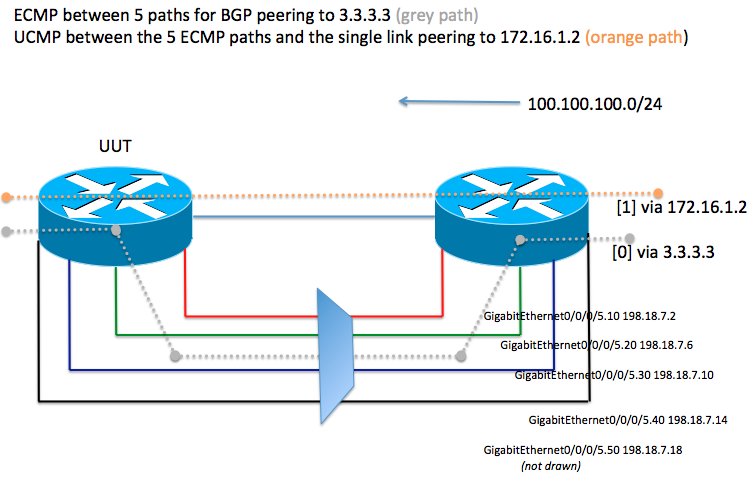
In the sample topology the UUT (on the left) has 5 equal cost paths for BGP peer 3.3.3.3.
It also has a BGP peering on 172.16.1.2 which is found via a unique single Gig Link.
For BGP peer 3.3.3.3 we can ECMP loadbalance between 5 gig paths.
Although in this example the 5 ECMP paths are found via the same physical interface and theoretically there is no need for UCMP here, we assume that these 5 ECMP paths are 5 unique gig links that effectively make it such that BGP peer 3.3.3.3 has 5 times more bandwidth then the BGP peer with address 172.16.1.2
2. Configuration
Associated configuration with this scenario from the UUT.
RP/0/RSP0/CPU0:PR-ASR9K-3#sh run router bgp
Tue Apr 23 08:22:14.769 UTC
router bgp 65003
bgp router-id 11.1.1.3
bgp log neighbor changes detail
bgp bestpath as-path multipath-relax
! Note this configuration line is required because we're going to do loadbalancing between paths that do not originate or come from
! the same AS. BGP by default would only do multipath on prefixes that follow the same AS PATH in IOS-XR.
address-family ipv4 unicast
maximum-paths ebgp 32
! Enable BGP multipath for 32 way. Note this requires the Typhoon based linecards. Trident linecards can only do
! 8 way eBGP/recursive loadbalancing
! The first BGP neighbor as per sample topology. Using eBGP multihop (because we are peering on loopback interfaces) and a
! route-policy that we use to allow all paths to be transported/advertised OUT and a policy on inbound to adjust the DMZ link
! bandwidth extended community.
neighbor 3.3.3.3
remote-as 65000
ebgp-multihop 255
update-source Loopback0
address-family ipv4 unicast
route-policy TRANSIT1_IN in
route-policy ALLOW_ALL out
!
! Second BGP neighbor definition
neighbor 172.16.1.2
remote-as 65001
address-family ipv4 unicast
route-policy TRANSIT0_IN in
route-policy ALLOW_ALL out
!
!
! Definition of the "pass-all" policy to advertise all prefixes unrestricted. Remember that an outbound route-policy is always required
! for eBGP peers in order to start advertising prefixes.
route-policy ALLOW_ALL
pass
end-policy
! Definition of the route policy that will adjust the DMZ link bandwidth.
! In the following scenario we are adjusting the BW to a factor 9 vs 1.
! In other words, for every 9Mb we send via path 3.3.3.3 we want to send 1Mb via path 172.16.1.2.
! ** In recent versions of IOSXR the link bandwidth is configured in units of Bytes per second [Bps] **
! So the conversion is [1Mbps == 1000 kbps == 1000000 bps == 125000 Bps]
! Hence (9Mbps : 1Mbps) --> ((125000*9) : (125000*1)) -->(1125000Bps : 125000Bps)
! Note that a possible better choice would have been 5 vs 1 because of the number of links and actual bandwidth of the circuits
! but this is for example purposes only and not meant to be a recommendation for the actual values to be used in a live network.
route-policy TRANSIT1_IN
if destination in (100.100.100.0/24) then
set extcommunity bandwidth (2906:1125000)
else
pass
endif
end-policy
route-policy TRANSIT0_IN
if destination in (100.100.100.0/24) then
set extcommunity bandwidth (2906:125000)
else
pass
endif
end-policy
3. Show commands and explanations
A detailed overview of all the related show commands that can be used to verify and prove the ECMP/UCMP functionality and how to troubleshoot the concept in case it is not working.
show bgp summary (to view the neighbor status)
RP/0/RSP0/CPU0:PR-ASR9K-3#show bgp sum
Tue Apr 23 08:21:34.686 UTC
BGP router identifier 11.1.1.3, local AS number 65003
BGP generic scan interval 60 secs
BGP table state: Active
Table ID: 0xe0000000 RD version: 24
BGP main routing table version 24
BGP scan interval 60 secs
BGP is operating in STANDALONE mode.
Process RcvTblVer bRIB/RIB LabelVer ImportVer SendTblVer StandbyVer
Speaker 24 24 24 24 24 24
Neighbor Spk AS MsgRcvd MsgSent TblVer InQ OutQ Up/Down St/PfxRcd
3.3.3.3 0 65000 16 17 24 0 0 00:08:38 5
172.16.1.2 0 65001 14 14 24 0 0 00:06:44 5
Output identifies that we have 5 prefixes received from both peers.
Our router ID is 11.1.1.3 and local AS is 65003. Out peers are in AS 65000 and 65001 and have been up for about 8 and 6 minutes respectively.
show bgp (to view the received and advertised prefixes)
RP/0/RSP0/CPU0:PR-ASR9K-3#show bgp
Tue Apr 23 08:21:51.562 UTC
BGP router identifier 11.1.1.3, local AS number 65003
BGP generic scan interval 60 secs
BGP table state: Active
Table ID: 0xe0000000 RD version: 24
BGP main routing table version 24
BGP scan interval 60 secs
Status codes: s suppressed, d damped, h history, * valid, > best
i - internal, r RIB-failure, S stale
Origin codes: i - IGP, e - EGP, ? - incomplete
Network Next Hop Metric LocPrf Weight Path
*> 11.11.11.0/25 3.3.3.3 0 65000 ?
*> 11.11.12.0/23 3.3.3.3 0 65000 ?
*> 99.1.1.1/32 172.16.1.2 0 0 65001 i
*> 99.3.3.3/32 0.0.0.0 0 32768 i
*> 99.5.5.5/32 172.16.1.2 0 65001 65000 65000 65000 65005 i
*> 100.80.100.0/24 3.3.3.3 0 65000 1234 ?
* 172.16.1.2 0 65001 1234 ?
*> 100.90.100.0/24 3.3.3.3 0 65000 1234 ?
* 172.16.1.2 0 65001 1234 ?
*> 100.100.100.0/24 3.3.3.3 0 65000 1234 ?
* 172.16.1.2 0 65001 1234 ?
Processed 8 prefixes, 11 paths
We can see a single locally originated prefix (99.3.3.3/32) because the next hop is 0.0.0.0 and we see a few prefixes that are advertised by our peers we have configured.
The most important prefix in this output in bold is the 100.100.100.0/24 because as per route policy we will modify the link bandwidth between the 2 neighbors.
show bgp <prefix> (To get the bgp prefix details, paths, attributes etc)
RP/0/RSP0/CPU0:PR-ASR9K-3#show bgp 100.100.100.0/24
Tue Apr 23 08:25:23.496 UTC
BGP routing table entry for 100.100.100.0/24
Versions:
Process bRIB/RIB SendTblVer
Speaker 20 20
Last Modified: Apr 23 08:14:56.885 for 00:10:26
Paths: (2 available, best #1)
Advertised to update-groups (with more than one peer):
0.4
Path #1: Received by speaker 0
Advertised to update-groups (with more than one peer):
0.4
65000 1234
3.3.3.3 from 3.3.3.3 (3.3.3.3)
Origin incomplete, localpref 100, valid, external, best, group-best, multipath
Received Path ID 0, Local Path ID 1, version 20
Extended community: LB:2906:9000
Origin-AS validity: not-found
Path #2: Received by speaker 0
Not advertised to any peer
65001 1234
172.16.1.2 from 172.16.1.2 (11.1.1.1)
Origin incomplete, localpref 100, valid, external, multipath
Received Path ID 0, Local Path ID 0, version 0
Extended community: LB:2906:1000
Origin-AS validity: not-found
The BGP selection algorithm chooses one path as the "best" based on the standard BGP selection criteria. Although now, since BGP multipath is enabled, both paths are tagged with the multipath keyword and should appear in the routing table for forwarding.
The extended community for link bandwidth is listed with the values that we had set in the route-policy. In recent versions of IOSXR the BGP output converts the bandwidth value from [Bps] to [kbps]. Hence 1125000Bps and 125000Bps becomes 9000kbps (9Mbps) and 1000kbps (1Mbps) respectively.
Note the 2 different AS paths for the 2 prefixes, normally Multipath would not work on that but considering the "relax" configuration under the BGP routing header we are allowing multipath to occur on these paths.
show route (to verify the table installation of the RIB)
B 100.100.100.0/24 [20/0] via 3.3.3.3, 01:40:17
[20/0] via 172.16.1.2, 01:40:17
RP/0/RSP0/CPU0:PR-ASR9K-3#show route 100.100.100.0/24
Tue Apr 23 08:25:58.349 UTC
Routing entry for 100.100.100.0/24
Known via "bgp 65003", distance 20, metric 0
Tag 65000, type external
Installed Apr 23 08:14:56.675 for 00:11:01
Routing Descriptor Blocks
3.3.3.3, from 3.3.3.3, BGP multi path
Route metric is 0, Wt is 9000
172.16.1.2, from 172.16.1.2, BGP multi path
Route metric is 0, Wt is 1000
No advertising protos.
In this output we can identify that we indeed have BGP multipath running. The prefix is installed for 2 paths exactly as we wanted.
The route detail shows that there is a weight of 9000kbps vs 11000kbps resulting from the applied route-policy to adjust link BW.
The portion where it says: "3.3.3.3, from 3.3.3.3, BGP multi path" effectively means that we learnt this path from the next hop 3.3.3.3 (in bold), and the router ID of that neighbor is "3.3.3.3" (non bold).
So now we have 2 next hops available and lets find out some details of that.
show route <nexthop>
RP/0/RSP0/CPU0:PR-ASR9K-3#show route 172.16.1.2
Tue Apr 23 08:26:16.799 UTC
Routing entry for 172.16.1.0/30
Known via "connected", distance 0, metric 0 (connected)
Installed Apr 23 08:10:11.329 for 00:16:05
Routing Descriptor Blocks
directly connected, via GigabitEthernet0/0/0/0
Route metric is 0
No advertising protos.
BGP nexthop 172.16.1.0 is directly peering on the physical interface address.
RP/0/RSP0/CPU0:PR-ASR9K-3#show route 3.3.3.3
Tue Apr 23 08:26:10.335 UTC
Routing entry for 3.3.3.3/32
Known via "static", distance 1, metric 0
Installed Apr 23 08:10:11.336 for 00:15:59
Routing Descriptor Blocks
198.18.7.2, via GigabitEthernet0/0/0/5.10
Route metric is 0
198.18.7.6, via GigabitEthernet0/0/0/5.20
Route metric is 0
198.18.7.10, via GigabitEthernet0/0/0/5.30
Route metric is 0
198.18.7.14, via GigabitEthernet0/0/0/5.40
Route metric is 0
198.18.7.18, via GigabitEthernet0/0/0/5.50
Route metric is 0
No advertising protos.
In this section you can identify that the BGP next hop 3.3.3.3 is found via 5 different IGP paths. We can tell that these IGP Paths are static routes because the metric is zero, distance is 1 and also as identified by the "learnt" source.
The static routes identify that we are finding the next hop address to be 192.18.7.x/30 via the dedicated interfaces that serve that address.
show cef <nexthop> detail
RP/0/RSP0/CPU0:PR-ASR9K-3#show cef 3.3.3.3/32 detail
Tue Apr 23 08:27:41.826 UTC
3.3.3.3/32, version 611, internal 0x4000001 (ptr 0x7178e220) [4], 0x0 (0x0), 0x0 (0x0)
Updated Apr 23 08:27:23.875
Prefix Len 32, traffic index 0, precedence routine (0), priority 3
gateway array (0x70f2524c) reference count 1, flags 0x8020, source rib (5), 0 backups
[1 type 3 flags 0x90111 (0x7105025c) ext 0x0 (0x0)]
LW-LDI[type=0, refc=0, ptr=0x0, sh-ldi=0x0]
Level 1 - Load distribution: 0 1 2 3 4
[0] via 198.18.7.2, recursive
[1] via 198.18.7.6, recursive
[2] via 198.18.7.10, recursive
[3] via 198.18.7.14, recursive
[4] via 198.18.7.18, recursive
via 198.18.7.2, 6 dependencies, recursive [flags 0x0]
path-idx 0 [0x7178e580 0x0]
next hop 198.18.7.2 via 198.18.7.2/32
Load distribution: 0 (refcount 1)
Hash OK Interface Address
0 Y GigabitEthernet0/0/0/5.10 remote
via 198.18.7.6, 6 dependencies, recursive [flags 0x0]
path-idx 1 [0x7178f444 0x0]
next hop 198.18.7.6 via 198.18.7.6/32
Load distribution: 0 (refcount 1)
Hash OK Interface Address
1 Y GigabitEthernet0/0/0/5.20 remote
via 198.18.7.10, 6 dependencies, recursive [flags 0x0]
path-idx 2 [0x7178e2f8 0x0]
next hop 198.18.7.10 via 198.18.7.10/32
Load distribution: 0 (refcount 1)
Hash OK Interface Address
2 Y GigabitEthernet0/0/0/5.30 remote
via 198.18.7.14, 6 dependencies, recursive [flags 0x0]
path-idx 3 [0x7178d728 0x0]
next hop 198.18.7.14 via 198.18.7.14/32
Load distribution: 0 (refcount 1)
Hash OK Interface Address
3 Y GigabitEthernet0/0/0/5.40 remote
via 198.18.7.18, 6 dependencies, recursive [flags 0x0]
path-idx 4 [0x7178e364 0x0]
next hop 198.18.7.18 via 198.18.7.18/32
Load distribution: 0 (refcount 1)
Hash OK Interface Address
4 Y GigabitEthernet0/0/0/5.50 remote
In this output you can see the 5 paths are available and hash numbered 0-4.
The address says "REMOTE" because the show cef command was done without a location keyword.
Because the location keyword is omitted we are looking at the RSP and this CEF adjacency is completed and lives on linecard 0.
This because the outgoing interface is G0/0/0/5.
We can get the local adj information by using the same command but with the location 0/0/CPU0 .
Important
Note that the most important part of this command is this :
via 198.18.7.14, 6 dependencies, recursive [flags 0x0]
This is going to break us, but lets verify...
Show cef with location
If we apply the location keyword in the show cef command, the output changes slightly to:
RP/0/RSP0/CPU0:PR-ASR9K-3#show cef 3.3.3.3 detail location 0/0/cpu0
Tue Apr 23 10:15:09.156 UTC
3.3.3.3/32, version 4471, internal 0x4000001 (ptr 0x8850f79c) [4], 0x0 (0x0), 0x
0 (0x0)
Updated Apr 23 10:14:45.907
Prefix Len 32, traffic index 0, precedence routine (0), priority 3
gateway array (0x878c007c) reference count 1, flags 0x8020, source rib (5), 0
backups
[1 type 3 flags 0x90111 (0x879eca78) ext 0x0 (0x0)]
LW-LDI[type=0, refc=0, ptr=0x0, sh-ldi=0x0]
Level 1 - Load distribution: 0 1 2 3 4
[0] via 198.18.7.2, recursive
[1] via 198.18.7.6, recursive
[2] via 198.18.7.10, recursive
[3] via 198.18.7.14, recursive
[4] via 198.18.7.18, recursive
via 198.18.7.2, 6 dependencies, recursive [flags 0x0]
path-idx 0 [0x8850ea0c 0x0]
next hop 198.18.7.2 via 198.18.7.2/32
Load distribution: 0 (refcount 1)
Hash OK Interface Address
0 Y GigabitEthernet0/0/0/5.10 198.18.7.2
via 198.18.7.6, 6 dependencies, recursive [flags 0x0]
path-idx 1 [0x88510e60 0x0]
next hop 198.18.7.6 via 198.18.7.6/32
Load distribution: 0 (refcount 1)
Hash OK Interface Address
1 Y GigabitEthernet0/0/0/5.20 198.18.7.6
via 198.18.7.10, 6 dependencies, recursive [flags 0x0]
path-idx 2 [0x8850fa08 0x0]
next hop 198.18.7.10 via 198.18.7.10/32
Load distribution: 0 (refcount 1)
Hash OK Interface Address
2 Y GigabitEthernet0/0/0/5.30 198.18.7.10
via 198.18.7.14, 6 dependencies, recursive [flags 0x0]
path-idx 3 [0x88510d68 0x0]
next hop 198.18.7.14 via 198.18.7.14/32
Load distribution: 0 (refcount 1)
Hash OK Interface Address
3 Y GigabitEthernet0/0/0/5.40 198.18.7.14
via 198.18.7.18, 6 dependencies, recursive [flags 0x0]
path-idx 4 [0x8850fa84 0x0]
next hop 198.18.7.18 via 198.18.7.18/32
Load distribution: 0 (refcount 1)
Hash OK Interface Address
4 Y GigabitEthernet0/0/0/5.50 198.18.7.18
The output is still the same conceptually, but now we get the right address information available.
show cef <BGP prefix> detail
RP/0/RSP0/CPU0:PR-ASR9K-3#show cef 100.100.100.0/24 det
Tue Apr 23 08:28:31.210 UTC
100.100.100.0/24, version 154, internal 0x14000001 (ptr 0x7178f294) [1], 0x0 (0x0), 0x0 (0x0)
Updated Apr 23 08:14:56.684
Prefix Len 24, traffic index 0, precedence routine (0), priority 4
gateway array (0x70f25164) reference count 1, flags 0x8020, source rib (5), 0 backups
[1 type 3 flags 0x80151 (0x710500b8) ext 0x0 (0x0)]
LW-LDI[type=0, refc=0, ptr=0x0, sh-ldi=0x0]
Weight distribution:
slot 0, weight 9000, normalized_weight 5
slot 1, weight 9000, normalized_weight 5
Level 1 - Load distribution: 0 1 2 3 4 5 6 7 8 9
[0] via 3.3.3.3, recursive
[1] via 172.16.1.2, recursive
via 3.3.3.3, 4 dependencies, recursive, bgp-ext, bgp-multipath [flags 0x60a0]
path-idx 0 [0x7178e220 0x0]
next hop 3.3.3.3 via 3.3.3.3/32
via 172.16.1.2, 15 dependencies, recursive, bgp-ext, bgp-multipath [flags 0x60a0]
path-idx 1 [0x7178f078 0x0]
next hop 172.16.1.2 via 172.16.1.2/32
Load distribution: _ _ _ _ _ _ _ _ _ _ (refcount 1)
Hash OK Interface Address
- Y GigabitEthernet0/0/0/5.50 remote
- Y GigabitEthernet0/0/0/5.10 remote
- Y GigabitEthernet0/0/0/5.20 remote
- Y GigabitEthernet0/0/0/5.30 remote
- Y GigabitEthernet0/0/0/5.40 remote
- Y GigabitEthernet0/0/0/0 remote
- Y GigabitEthernet0/0/0/0 remote
- Y GigabitEthernet0/0/0/0 remote
- Y GigabitEthernet0/0/0/0 remote
- Y GigabitEthernet0/0/0/0 remote
Now look at this output for the BGP prefix. This is NOT what we expected!
The hash buckets are shared equally. That is, I have 10 buckets (normalized weight is 5), and they are spread 5 on 5 between the 2 paths.
Then for the path that has multiple IGP paths for its next hop, we share it over the 5 IGP paths
Problem and explanation
Now the issue is that the IGP next hop is recursive as what we saw before when checking the 3.3.3.3 next hop.
When using UCMP, the ADJ leafs need to be equal in length so to speak.
To visualize it, see this:

In our outputs above from the show cef 3.3.3.3 we saw that the adj was recursive, this means that the black ADJ in this picture still has another step down to get to the bottom or final leaf.
This is caused by the fact how the static routes are defined:
| Static routing config |
|---|
router static address-family ipv4 unicast 3.3.3.3/32 198.18.7.2 3.3.3.3/32 198.18.7.6 3.3.3.3/32 198.18.7.10 3.3.3.3/32 198.18.7.14 3.3.3.3/32 198.18.7.18 |
In IOS this is perfectly fine, this is a direct next hop and no recursion. However in IOS-XR this is not a direct ADJ.
this because theoretically and technically the 198.18.7.2 for instance could also be found via another interface that doesn't necessarily own this address or is maybe sharing this address in an unnumbered fashion.
In order for us to tie the next hop to an interface we need to specify the interface like this:
| Static routing config NEW |
|---|
router static address-family ipv4 unicast 3.3.3.3/32 GigabitEthernet0/0/0/5.10 198.18.7.2 3.3.3.3/32 GigabitEthernet0/0/0/5.20 198.18.7.6 3.3.3.3/32 GigabitEthernet0/0/0/5.30 198.18.7.10 3.3.3.3/32 GigabitEthernet0/0/0/5.40 198.18.7.14 3.3.3.3/32 GigabitEthernet0/0/0/5.50 198.18.7.18 |
With this new config we removed the recursion from the static routes and now UCMP should start to work.
Let's verify.
Show cef bgp next hop after recursion removal
RP/0/RSP0/CPU0:PR-ASR9K-3#show cef 3.3.3.3/32 detail
Tue Apr 23 08:30:21.315 UTC
3.3.3.3/32, version 695, internal 0x4000001 (ptr 0x7178e220) [7], 0x0 (0x7114a208), 0x0 (0x0)
Updated Apr 23 08:28:59.989
remote adjacency to GigabitEthernet0/0/0/5.10
Prefix Len 32, traffic index 0, precedence routine (0), priority 3
gateway array (0x70f25504) reference count 1, flags 0x0, source rib (5), 0 backups
[2 type 3 flags 0x10101 (0x71050298) ext 0x0 (0x0)]
LW-LDI[type=3, refc=1, ptr=0x7114a208, sh-ldi=0x71050298]
via 198.18.7.2, GigabitEthernet0/0/0/5.10, 4 dependencies, weight 0, class 0 [flags 0x0]
path-idx 0 [0x7213a560 0x0]
next hop 198.18.7.2
remote adjacency
via 198.18.7.6, GigabitEthernet0/0/0/5.20, 4 dependencies, weight 0, class 0 [flags 0x0]
path-idx 1 [0x7213a5bc 0x0]
next hop 198.18.7.6
remote adjacency
via 198.18.7.10, GigabitEthernet0/0/0/5.30, 4 dependencies, weight 0, class 0 [flags 0x0]
path-idx 2 [0x7213a618 0x0]
next hop 198.18.7.10
remote adjacency
via 198.18.7.14, GigabitEthernet0/0/0/5.40, 4 dependencies, weight 0, class 0 [flags 0x0]
path-idx 3 [0x7213a674 0x0]
next hop 198.18.7.14
remote adjacency
via 198.18.7.18, GigabitEthernet0/0/0/5.50, 4 dependencies, weight 0, class 0 [flags 0x0]
path-idx 4 [0x7213a6d0 0x0]
next hop 198.18.7.18
remote adjacency
Load distribution: 0 1 2 3 4 (refcount 2)
Hash OK Interface Address
0 Y GigabitEthernet0/0/0/5.10 remote
1 Y GigabitEthernet0/0/0/5.20 remote
2 Y GigabitEthernet0/0/0/5.30 remote
3 Y GigabitEthernet0/0/0/5.40 remote
4 Y GigabitEthernet0/0/0/5.50 remote
Note the recursive keyword is no longer seen on the highlighted line.
4. Solution verification
RP/0/RSP0/CPU0:PR-ASR9K-3#show cef 100.100.100.0/24 detail
Tue Apr 23 08:29:08.098 UTC
100.100.100.0/24, version 154, internal 0x14000001 (ptr 0x7178f294) [1], 0x0 (0x0), 0x0 (0x0)
Updated Apr 23 08:14:56.684
Prefix Len 24, traffic index 0, precedence routine (0), priority 4
gateway array (0x70f25164) reference count 1, flags 0x8020, source rib (5), 0 backups
[1 type 3 flags 0x80111 (0x710500b8) ext 0x0 (0x0)]
LW-LDI[type=0, refc=0, ptr=0x0, sh-ldi=0x0]
Weight distribution:
slot 0, weight 9000, normalized_weight 9
slot 1, weight 1000, normalized_weight 1
Level 1 - Load distribution: 0 1 0 0 0 0 0 0 0 0
[0] via 3.3.3.3, recursive
[1] via 172.16.1.2, recursive
via 3.3.3.3, 7 dependencies, recursive, bgp-ext, bgp-multipath [flags 0x60a0]
path-idx 0 [0x7178e220 0x0]
next hop 3.3.3.3 via 3.3.3.3/32
Load distribution: 0 1 2 3 4 (refcount 1)
Hash OK Interface Address
0 Y GigabitEthernet0/0/0/5.10 remote
1 Y GigabitEthernet0/0/0/5.20 remote
2 Y GigabitEthernet0/0/0/5.30 remote
3 Y GigabitEthernet0/0/0/5.40 remote
4 Y GigabitEthernet0/0/0/5.50 remote
via 172.16.1.2, 7 dependencies, recursive, bgp-ext, bgp-multipath [flags 0x60a0]
path-idx 1 [0x7178f078 0x0]
next hop 172.16.1.2 via 172.16.1.2/32
Load distribution: 0 (refcount 1)
Hash OK Interface Address
5 Y GigabitEthernet0/0/0/0 remote
Now we have the weight ratio we expect. there are 10 buckets total (9 + 1) and you can see that path with index 0 (using 3.3.3.3) is seen 9 times in the buckets and that the path via 172.16.1.2 with index 1 is only used one time.
The remote keyword is seen here for the same reasons as before, considering that the location keyword was not used in the show command.
Remote means here, not local to the NODE we are invoking the command on.
Show command with location
RP/0/RSP0/CPU0:PR-ASR9K-3#show cef 100.100.100.0/24 detail location 0/0/CPU0
Tue Apr 23 08:29:34.842 UTC
100.100.100.0/24, version 154, internal 0x14000001 (ptr 0x88510b78) [1], 0x0 (0x0), 0x0 (0x0)
Updated Apr 23 08:14:56.684
Prefix Len 24, traffic index 0, precedence routine (0), priority 4
gateway array (0x878bfe38) reference count 1, flags 0x8020, source rib (5), 0 backups
[1 type 3 flags 0x80111 (0x879ec5b8) ext 0x0 (0x0)]
LW-LDI[type=0, refc=0, ptr=0x0, sh-ldi=0x0]
Weight distribution:
slot 0, weight 9000, normalized_weight 9
slot 1, weight 1000, normalized_weight 1
Level 1 - Load distribution: 0 1 0 0 0 0 0 0 0 0
[0] via 3.3.3.3, recursive
[1] via 172.16.1.2, recursive
via 3.3.3.3, 7 dependencies, recursive, bgp-ext, bgp-multipath [flags 0x60a0]
path-idx 0 [0x8850f79c 0x0]
next hop 3.3.3.3 via 3.3.3.3/32
Load distribution: 0 1 2 3 4 (refcount 1)
Hash OK Interface Address
0 Y GigabitEthernet0/0/0/5.10 198.18.7.2
1 Y GigabitEthernet0/0/0/5.20 198.18.7.6
2 Y GigabitEthernet0/0/0/5.30 198.18.7.10
3 Y GigabitEthernet0/0/0/5.40 198.18.7.14
4 Y GigabitEthernet0/0/0/5.50 198.18.7.18
via 172.16.1.2, 7 dependencies, recursive, bgp-ext, bgp-multipath [flags 0x60a0]
path-idx 1 [0x8850f818 0x0]
next hop 172.16.1.2 via 172.16.1.2/32
Load distribution: 0 (refcount 1)
Hash OK Interface Address
5 Y GigabitEthernet0/0/0/0 172.16.1.2
With the location keyword the address and full adj are shown.
5.
Related Information
Xander Thuijs CCIE #6775
Principal Engineer ASR9000
- Mark as Read
- Mark as New
- Bookmark
- Permalink
- Report Inappropriate Content
it's cool ! wondering if the weight community could be passed to an ibgg peer and split the traffic as described in belowing diagram? what if the traffic and BGP peering are in a VRF ?
thanks
- Mark as Read
- Mark as New
- Bookmark
- Permalink
- Report Inappropriate Content
communities in general are transitive and advertised to peers, so that shouldnt be a problem.
but for iBGP loadbalancing, generally BGP only advertises the best path down into the AS, so other BGP
speakers basically find the path to this exit point via the IGP/inside the AS.
In that regard inside the AS the loadbalancing is "controlled" by the IGP.
vrf's in play doesnt really matter for this scenario, except for the fact that if a route resides in a different vrf
as to where the actual traffic is, then we may need to do route leaking, but that is unrelated to the dmz link banwidth
functionality.
cheers
xander
- Mark as Read
- Mark as New
- Bookmark
- Permalink
- Report Inappropriate Content
Hi Xander, what is number 2906 means? Can I use any random value?
route-policy TRANSIT1_IN
if destination in (100.100.100.0/24) then
set extcommunity bandwidth (2906:1125000)
else
pass
endif
end-policy
Also, I read at Cisco XR config guide about how to enable BGP Link Bandwidth. Will it achieve the same result by this way?
http://www.cisco.com/c/en/us/td/docs/routers/crs/software/crs_r4-3/routing/configuration/guide/b_routing_cg43xcrs/b_routing_cg43xcrs_chapter_010.html#task_1416191
Thanks.
- Mark as Read
- Mark as New
- Bookmark
- Permalink
- Report Inappropriate Content
Hi Eric,
According to the specification of the BGP dmz bandwidth community the global administrator portion of the extended community should represent the local Autonomous system number.
This is the way extended communities are "formatted":
    0                   1                   2                   3
    0 1 2 3 4 5 6 7 8 9 0 1 2 3 4 5 6 7 8 9 0 1 2 3 4 5 6 7 8 9 0 1
   +-+-+-+-+-+-+-+-+-+-+-+-+-+-+-+-+-+-+-+-+-+-+-+-+-+-+-+-+-+-+-+-+
   | 0x00 or 0x40  |   Sub-Type    |    Global Administrator       |
   +-+-+-+-+-+-+-+-+-+-+-+-+-+-+-+-+-+-+-+-+-+-+-+-+-+-+-+-+-+-+-+-+
   |                     Local Administrator                       |
   +-+-+-+-+-+-+-+-+-+-+-+-+-+-+-+-+-+-+-+-+-+-+-+-+-+-+-+-+-+-+-+-+
for Bandwidth the sub-type is "04", the global administrator was designated for the local AS and the local administrator is an IEEE float representation in bits per second of the bw desired.
cheers
xander
- Mark as Read
- Mark as New
- Bookmark
- Permalink
- Report Inappropriate Content
forgot to comment, the AIGP (or accumulated igp) metric is a new value that can be used for path selection to use the igp metric cost and have it represented in the bgp path. (whereas normally BGP is not "sensitive" to bandwidth.
depending on your scenario as to what you want to achieve, this AIGP may be able to do what you want also to influence path selection.
xander
- Mark as Read
- Mark as New
- Bookmark
- Permalink
- Report Inappropriate Content
Hi Xander, according to you explanation,
1st bytes = 0x00 or 0x40
2nd bytes (sub-type) = 0x04 (for BGP link bandwidth)
3rd and 4th bytes (global administrator) = local AS number
Local Administrator = Bandwidth parameter in bits per second.
if using AS number 65003 as in your example, than don't we should use these numbers instead of 2906?
1st bytes = 0x00 or 0x40
2nd bytes (sub-type) = 0x04
3rd and 4th bytes (global administrator) = 0xFDEB --> The hex number of 65003
Local Administrator = 1125000
The numbers will be 0x0004FDEB or 0x4004FDEB
or in decimal will be 327147 or 1074068971.
The configuration of RPL will be like this:
route-policy TRANSIT1_IN
if destination in (100.100.100.0/24) then
set extcommunity bandwidth (327147:1125000)
else
pass
endif
end-policy
Is it correct?
Thanks.
- Mark as Read
- Mark as New
- Bookmark
- Permalink
- Report Inappropriate Content

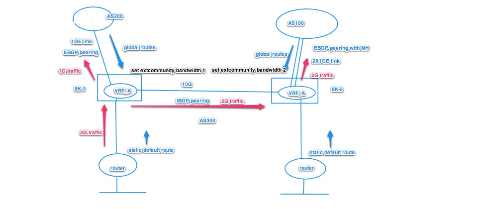
Hi Xander,
the topology is as above drawing. The R1 wants to load balance traffic into 4 links to destination at ASN 23. There are two 10GB links, and two 40GB links. R2 and R3 are connected to R1 using external BGP.
According to Cisco Config Guide, I can configure R1 by this way:
1. configure
2. router bgp as-number
3. address-family { ipv4 | ipv6 } unicast
4. maximum-paths { ebgp | ibgp | eibgp } maximum [ unequal-cost ]
5. exit
6. neighbor ip-address
7. dmz-link-bandwidth
8. Use the commit or end command.
It doesn't use RPL to define bandwith ratio like you mention before. Will this command "dmz-link-bandwidth" calculate the bandwidth ratio automatically similar like in IOS? or in XR we need to configure bandwidth ratio manually in RPL?
Thanks.
- Mark as Read
- Mark as New
- Bookmark
- Permalink
- Report Inappropriate Content
hi eric,
nice catch and indeed, if I had done this "properly" then I should have used AS 65003 and not 2906. Note that the AS number is merely a "cosmetic" or representation thing and doesnt affect the functionality.
For the BW encoding; yeah here some deal... the encoding per standard is bits per second... and that on size of the variable would not allow you to encode 40 or 100G...!
but since this is ratio in the end anyway, you can "scale down" the numbers to fit the var size to achieve that ratio.
Example: Say you have 100G and 40G links that is a ratio of 2.5 to 1. Then we could target a reference bw of say 125000. And we call 125000 "40G". then for the 100G link we just provide 2.5 times that 125000 number. the FIB/forwarding will automatically start to use these vals as a 1:2.5 ratio as we want!
The show command for the community may give us "inaccurate" bandwidth, because of our scale.
yeah tricky, not my call either... why on earth putting bw in bps, but hey I didnt write this standard :)
cheers!
xander
- Mark as Read
- Mark as New
- Bookmark
- Permalink
- Report Inappropriate Content
hi eric,
yeah that will provide for automatic identification of the bandwidth. For link speeds 40G and greater, you will need to resort to manual scaling due o the size of the variable in the community.
Best is to use RPL for better control and define a scale factor and provide "scales" on the neighbor path depending on how much BW there is available.
As a matter of fact I am working with our bgp folks to automate this a bit more, but right now we're bound by what the standards dictate (I have to have a solution that is compliant but also usable/flexible to accommodate scenarios like this you have).
cheers
xander
")
- Mark as Read
- Mark as New
- Bookmark
- Permalink
- Report Inappropriate Content
Hi Xander,
great explanation ! Just some points to be clarified....
In the scenario where bgp next-hop recursion is not fixed we can see for CEF load distribution (show cef 100.100.100.0/24 detail)
Load distribution: _ _ _ _ _ _ _ _ _ _ (refcount 1)
Hash OK Interface Address
- Y GigabitEthernet0/0/0/5.50 remote
- Y GigabitEthernet0/0/0/5.10 remote
- Y GigabitEthernet0/0/0/5.20 remote
- Y GigabitEthernet0/0/0/5.30 remote
- Y GigabitEthernet0/0/0/5.40 remote
- Y GigabitEthernet0/0/0/0 remote
- Y GigabitEthernet0/0/0/0 remote
- Y GigabitEthernet0/0/0/0 remote
- Y GigabitEthernet0/0/0/0 remote
- Y GigabitEthernet0/0/0/0 remote
Now it seems Level 1 distribution is not working as designed (hash index -> path index map is empty; we can see just "_" for each hash bucket index). Anyway under it a complete list of IGP paths is shown...
As far as I know, FIB architecture is based on a hierarchical structure. What about the related load balancing architecture ? Or in another words: how does it work under the hood ?
Thanks
- Mark as Read
- Mark as New
- Bookmark
- Permalink
- Report Inappropriate Content
hi carlo,
thanks! :) I have another doc on route scale architecture for the asr9000. Eventhough it explains the FIB implementation for the Trident NPU, (typhoon uses MTRIE), the logic of the FIB hierarchy remains the same.
FIB flattening was done in IOS, which effectively is what CEF does right, it provides a simple single lookup structure that goes from ROUTE->interface+encap(=mac rewrite)+features.
Flattening is nice for simple processors because it is fast for forwarding, but eliminates the ability to do good loadbalancing, convergence, but it consumes less memory.
Hierarchical FIB gives you the ability to make pointer flips from one BGP path to another, or from one IGP next hop and converge all the recursive prefixes that use that next hop (aka BGP PIC).
What I love about the commands explained here is the level of detail that they provide. But there is also too much information in there for the normal human mind. eg ptr references and the like are nice when there are crashes so it can easily be referenced/looked up in memory core dumps, but for troubleshooting "normal" forwarding or verifying it it serves no purpose.
With that said, the hash ref provided is not the fact that hash value 1 or 4 is actually deriving that link to be chosen, but merely an index used in the scheme of equal vs unequal balancing.
cheers!
xander
- Mark as Read
- Mark as New
- Bookmark
- Permalink
- Report Inappropriate Content
Hi, a lot of time has passed but reading again this post a doubt arose me about the following point: in the above scenario, at the end of the day, which is actually the traffic distribution between the 5+1 "logical" Giga links ?
The distribution between the 2 BGP path (3.3.3.3 and 172.16.1.2) is the one expected ( 9/10 vs 1/10) but what about the traffic distribution over the 5 + 1 IGP paths ? The single 1 Giga link (172.16.1.2) will be really utilized with ratio 1/10 or it will be just 1/6 of the overall load ?
Regards.
Find answers to your questions by entering keywords or phrases in the Search bar above. New here? Use these resources to familiarize yourself with the community: