- Cisco Community
- Technology and Support
- Service Providers
- Service Providers Knowledge Base
- ASR9000/XR Using PVSTAG (with Cluster and Satellite example)
- Subscribe to RSS Feed
- Mark as New
- Mark as Read
- Bookmark
- Subscribe
- Printer Friendly Page
- Report Inappropriate Content
 - Emeritus")
- Subscribe to RSS Feed
- Mark as New
- Mark as Read
- Bookmark
- Subscribe
- Printer Friendly Page
- Report Inappropriate Content
on 10-01-2013 10:36 AM
Introduction
This document provides a sample configuration for Per-VLAN Spanning-Tree Access Gateway (PVSTAG).
It shows as well a complete example of a PVSTAG configuration on a cluster with satellite.
Spanning-Tree Access Gateway
For scalability and complexity reasons it's not adviseable to run full Spanning Tree protocol on NPE and across the core, especially in a high-scale environment. Spanning-Tree Access Gateway terminates multiple Ethernet access rings on NPE without running full STP, where each ring can have its own independent topology. Access nodes speak the regular spanning-tree protocol, while the NPE only propagates topology changes (TCN).
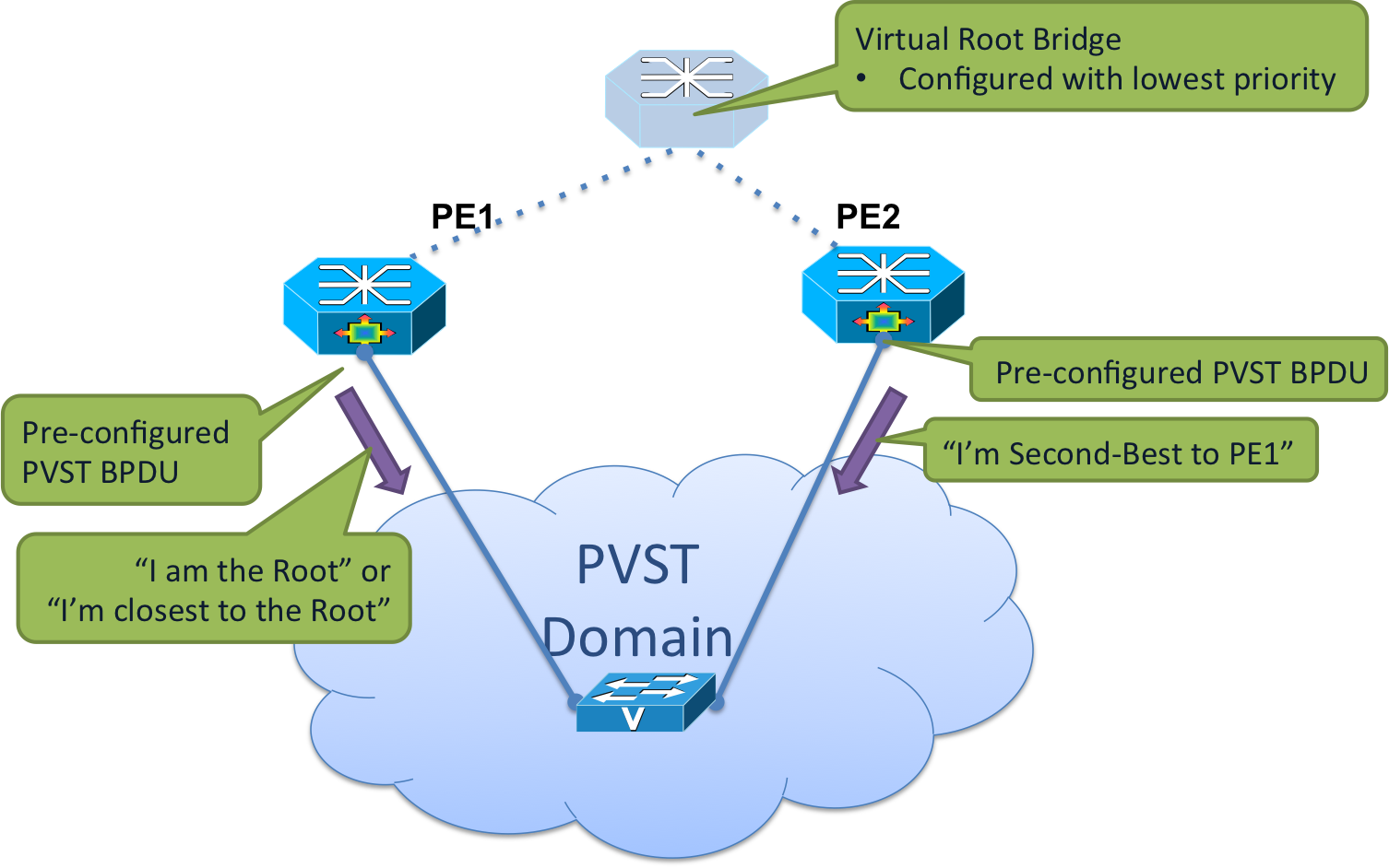
ST AG ports send preconfigured BPDU's with root or zero cost to root information towards access network. Both NPEs can send the same information or arbitrarily can be set as best and second best bridge via priority or cost setting for load balancing purposes. Root bridge can be one of the NPE's or arbitrarily set non-existent bridge address. ST AG ports are always in Designated state and are forwarding. All convergence operations and port state transitioning happen in the access network, which runs the regular ST protocol.
MST-AG is explained in ASR9000/XR Using MST-AG (MST Access Gateway), MST and VPLS. This document explains Per-VLAN Spanning-Tree Access Gateway (PVSTAG) on ASR9000.
Please note that in PVSTAG implementaton on ASR9000 only a single access device can be attached to the gateway devices.
PVSTAG Operation
PVSTAG Example #1

Configuration
| PE1 | PE2 |
|---|---|
spanning-tree pvstag inst4 interface GigabitEthernet1/0/0/23 vlan 4 root-priority 4096 root-id 0011.0011.0011 priority 8192 bridge-id 0011.0011.0011 port-priority 128 ! interface Loopback0 ipv4 address 10.1.1.1 255.255.255.255 ! interface GigabitEthernet1/0/0/23.4 l2transport encapsulation dot1q 4 rewrite ingress tag pop 1 symmetric ! l2vpn bridge group bg1 bridge-domain bd1 interface GigabitEthernet1/0/0/23.4 vfi vfi1 neighbor 10.2.2.2 pw-id 11 neighbor 10.3.3.3 pw-id 11 |
spanning-tree pvstag inst4 interface GigabitEthernet2/0/0/23 vlan 4 root-priority 4096 root-id 0011.0011.0011 priority 8192 bridge-id 0022.0022.0022 port-priority 128 ! interface Loopback0 ipv4 address 10.2.2.2 255.255.255.255 ! interface GigabitEthernet2/0/0/23.4 l2transport encapsulation dot1q 4 rewrite ingress tag pop 1 symmetric ! l2vpn bridge group bg1 bridge-domain bd1 interface GigabitEthernet2/0/0/23.4 vfi vfi1 neighbor 10.1.1.1 pw-id 11 neighbor 10.3.3.3 pw-id 11 |
PVSTAG Example #2: PVSTAG on a Cluster with Satellite
One interesting application of PVSTAG is in a Cluster. For higher scale fanout, Cluster in this example has Satellite switches.
In this example there is no VPLS in the core. Cluster is providing L3 termination through a routed interface (BVI). PVSTAG is configured in this scenario with a sole purpose of eliminating full spanning tree from the cluster.
The topology shown in the diagram was build just to illustrate use of PVSTAG, hence there is only one access switch in the topology. It could be replaced in the real network with a ring of access switches.

Configuration
| Cluster | 3750 |
|---|---|
! spanning-tree pvstag inst4 interface GigabitEthernet101/0/0/23 vlan 4 root-priority 4096 root-id 0011.0011.0011 priority 8192 bridge-id 0011.0011.0011 port-priority 128 ! ! interface GigabitEthernet102/0/0/23 vlan 4 root-priority 4096 root-id 0011.0011.0011 priority 8192 bridge-id 0022.0022.0022 port-priority 128 ! ! ! interface Loopback100 ipv4 address 8.8.8.8 255.255.255.255 ! interface Loopback201 ipv4 address 9.9.9.9 255.255.255.255 ! interface GigabitEthernet101/0/0/23 cdp ! interface GigabitEthernet102/0/0/23 cdp ! interface GigabitEthernet101/0/0/23.4 l2transport encapsulation dot1q 4 rewrite ingress tag pop 1 symmetric ! interface GigabitEthernet102/0/0/23.4 l2transport encapsulation dot1q 4 rewrite ingress tag pop 1 symmetric ! interface TenGigE0/0/0/0 ipv4 point-to-point ipv4 unnumbered Loopback100 nv satellite-fabric-link satellite 101 remote-ports GigabitEthernet 0/0/0-43 ! ! ! interface TenGigE0/0/2/0 nv edge interface ! ! ! interface TenGigE0/0/2/1 nv edge interface ! ! ! interface TenGigE1/0/0/0 ipv4 point-to-point ipv4 unnumbered Loopback201 nv satellite-fabric-link satellite 102 remote-ports GigabitEthernet 0/0/0-43 ! ! ! interface BVI5 ipv4 address 4.4.4.1 255.255.255.0 ! l2vpn bridge group bg1 bridge-domain bd1 interface GigabitEthernet101/0/0/23.4 ! interface GigabitEthernet102/0/0/23.4 ! routed interface BVI5 ! ! ! nv satellite 101 type asr9000v serial-number CAT1641U0QV ipv4 address 10.22.1.2 ! satellite 102 type asr9000v serial-number CAT1635U14B ipv4 address 10.23.1.2 ! |
! interface GigabitEthernet4/0/23 switchport trunk encapsulation dot1q switchport trunk allowed vlan 4 switchport mode trunk ! interface GigabitEthernet4/0/24 switchport trunk encapsulation dot1q switchport trunk allowed vlan 4 switchport mode trunk ! interface Vlan4 ip address 4.4.4.2 255.255.255.0 ! |
Verify
| CLI Command | Description |
|---|---|
show l2vpn bridge-domain bd-name <name> | Confirm that all required access circuits, PWs and VFIs are part of the bridge group. Confirm their status. |
| show spanning-tree pvstag <instance> | Check whether PVSTAG configuration is applied as expected on access (sub)interfaces. Both (sub)interfaces should be active because the PE(s) running PVSTAG must have the lowest cost to the root. |
show l2vpn forwarding bridge-domain <bridge-domain>:<bridge-group> mac-address location <location> | Confirm that MAC addresses are properly learned. If this is a lab scenario, don't forget that you actually need some traffic to be received from the access network. |
| show arp <interface> | In this particular example L3 is terminated on the BVI interface of the cluster PE. Hence it makes sense to confirm the ARP entries associated with the BVI interface. |
Captures from the routers shown in the above diagram:
RP/0/RSP0/CPU0:ASR9001-1#sh l2vpn bridge-domain bd-name bd1
Fri Sep 27 21:08:10.945 UTC
Legend: pp = Partially Programmed.
Bridge group: bg1, bridge-domain: bd1, id: 0, state: up, ShgId: 0, MSTi: 0
  Aging: 300 s, MAC limit: 4000, Action: none, Notification: syslog
  Filter MAC addresses: 0
  ACs: 3 (3 up), VFIs: 0, PWs: 0 (0 up), PBBs: 0 (0 up)
  List of ACs:
    BV5, state: up, BVI MAC addresses: 1
    Gi101/0/0/23.4, state: up, Static MAC addresses: 0
    Gi102/0/0/23.4, state: up, Static MAC addresses: 0
  List of Access PWs:
  List of VFIs:

RP/0/RSP0/CPU0:ASR9001-1#sh spanning-tree pvstag inst4
Fri Sep 27 19:15:26.616 UTC
GigabitEthernet101/0/0/23
  VLAN 4    Pre-empt delay is disabled
    Sub-interface:    GigabitEthernet101/0/0/23.4 (Up)    Max Age:          20
    Root Priority:    4096    Root Bridge:      0011.0011.0011    Cost:             0
    Bridge Priority:  8192
    Bridge ID:        0011.0011.0011    Port Priority:    128
    Port ID           1
    Hello Time:       2
    Active:           Yes    BPDUs sent:       159921
    Topology Changes: 4

GigabitEthernet102/0/0/23
  VLAN 4
    Pre-empt delay is disabled
    Sub-interface:    GigabitEthernet102/0/0/23.4 (Up)    Max Age:          20
    Root Priority:    4096    Root Bridge:      0011.0011.0011    Cost:             0
    Bridge Priority:  8192
    Bridge ID:        0022.0022.0022    Port Priority:    128
    Port ID           1
    Hello Time:       2
    Active:           Yes    BPDUs sent:       159894
    Topology Changes: 1

RP/0/RSP0/CPU0:ASR9001-1#sh l2vpn forwarding bridge-domain bg1:bd1 mac-address location 0/0/CPU0
Fri Sep 27 21:33:11.080 UTC
 To Resynchronize MAC table from the Network Processors, use the command...
    l2vpn resynchronize forwarding mac-address-table location
Mac Address    Type    Learned from/Filtered on    LC learned Resync Age         Mapped to
--------------------------------------------------------------------------------
000f.8f35.2643 dynamic Gi101/0/0/23.4              0/0/CPU0   0d 0h 0m 13s       N/A
8478.ac35.8265 routed  BD id: 0                    N/A        N/A                N/A

RP/0/RSP0/CPU0:ASR9001-1#sh arp bvi 5
Fri Sep 27 21:36:29.438 UTC

-------------------------------------------------------------------------------
1/0/CPU0
-------------------------------------------------------------------------------
Address         Age        Hardware Addr   State      Type  Interface
4.4.4.1         -          8478.ac35.8265  Interface  ARPA  BVI5
4.4.4.2         00:03:48   000f.8f35.2643  Dynamic    ARPA  BVI5

-------------------------------------------------------------------------------
0/0/CPU0
-------------------------------------------------------------------------------
Address         Age        Hardware Addr   State      Type  Interface
4.4.4.1         -          8478.ac35.8265  Interface  ARPA  BVI5
4.4.4.2         00:03:49   000f.8f35.2643  Dynamic    ARPA  BVI5
Capture from the 3750 switch:
3750#sh spanning-tree vlan 4 VLAN0004
  Spanning tree enabled protocol ieee
  Root ID    Priority    4096             Address     0011.0011.0011             Cost        4
             Port        179 (GigabitEthernet4/0/23)
             Hello Time   2 sec  Max Age 20 sec  Forward Delay 15 sec

  Bridge ID  Priority    32772  (priority 32768 sys-id-ext 4)
             Address     000f.8f35.2600
             Hello Time   2 sec  Max Age 20 sec  Forward Delay 15 sec
             Aging Time 300

Interface        Role Sts Cost      Prio.Nbr Type
---------------- ---- --- --------- -------- --------------------------------
Gi4/0/23         Root FWD 4         128.179  P2p
Gi4/0/24         Altn BLK 4         128.180  P2p
Related Information
For more information refer to the Implementing Multiple Spanning Tree Protocol section of Cisco ASR 9000 Series Aggregation Services Router L2VPN and Ethernet Services Configuration Guide, Release 4.3.x.
- Mark as Read
- Mark as New
- Bookmark
- Permalink
- Report Inappropriate Content
Hi Aleksandar,
Very interesting your article
In here i got PVSTAG force ASR to become root bridge, to make it appear on the top of ASR there was another node act as root bridge. So all path in forwarding condition with no one blocking. Correct me if im wrong.
Regards,
Randy
- Mark as Read
- Mark as New
- Bookmark
- Permalink
- Report Inappropriate Content
hi Randy,
your understanding is correct.
regards,
Aleksandar
- Mark as Read
- Mark as New
- Bookmark
- Permalink
- Report Inappropriate Content
Dear Aleksandar,
Thanks for response. Im using bundle-ether for this pvstag link, bundle-ether is up, mac-address and arp BVI was detected.
But i found my bundle-ether disable in pvstag instance like below.
RP/0/RSP0/CPU0:LAB1-ASR9K#sh spanning-tree pvstag PVST
Tue Jul 26 00:34:43.990 UTC
Bundle-Ether10
VLAN 10
Pre-empt delay is disabled
Sub-interface: Bundle-Ether10.10 (Down)
Max Age: 20
Root Priority: 0
Root Bridge: 0000.0041.0221
Cost: 0
Bridge Priority: 0
Bridge ID: 70e4.2216.68b3
Port Priority: 0
Port ID 0
Hello Time: 2
Active: No
BPDUs sent: 0
Topology Changes: 0
Regards,
Randy
- Mark as Read
- Mark as New
- Bookmark
- Permalink
- Report Inappropriate Content
hi Randy,
did you check the status of the attachment circuit?
It will help if you attach a topology diagram, running config and the output of all commands listed in the document above.
regards,
/Aleksandar
Find answers to your questions by entering keywords or phrases in the Search bar above. New here? Use these resources to familiarize yourself with the community: