- Cisco Community
- Technology and Support
- Service Providers
- Service Providers Knowledge Base
- ASR9000/XR: Understanding QOS, default marking behavior and troubleshooting
- Subscribe to RSS Feed
- Mark as New
- Mark as Read
- Bookmark
- Subscribe
- Printer Friendly Page
- Report Inappropriate Content
- Subscribe to RSS Feed
- Mark as New
- Mark as Read
- Bookmark
- Subscribe
- Printer Friendly Page
- Report Inappropriate Content
03-07-2011 01:43 PM - edited 12-18-2018 05:19 AM
Introduction
This document provides details on how QOS is implemented in the ASR9000 and how to interpret and troubleshoot qos related issues.
Core Issue
QOS is always a complex topic and with this article I'll try to describe the QOS architecture and provide some tips for troubleshooting.
Based on feedback on this document I'll keep enhancing it to document more things bsaed on that feedback.
The ASR9000 employs an end to end qos architecture throughout the whole system, what that means is that priority is propagated throughout the systems forwarding asics. This is done via backpressure between the different fowarding asics.
One very key aspect of the A9K's qos implementation is the concept of using VOQ's (virtual output queues). Each network processor, or in fact every 10G entity in the system is represented in the Fabric Interfacing ASIC (FIA) by a VOQ on each linecard.
That means in a fully loaded system with say 24 x 10G cards, each linecard having 8 NPU's and 4 FIA's, a total of 192 (24 times 8 slots) VOQ's are represented at each FIA of each linecard.
The VOQ's have 4 different priority levels: Priority 1, Priority 2, Default priority and multicast.
The different priority levels used are assigned on the packets fabric headers (internal headers) and can be set via QOS policy-maps (MQC; modular qos configuration).
When you define a policy-map and apply it to a (sub)interface, and in that policy map certain traffic is marked as priority level 1 or 2 the fabric headers will represent that also, so that this traffic is put in the higher priority queues of the forwarding asics as it traverses the FIA and fabric components.
If you dont apply any QOS configuration, all traffic is considered to be "default" in the fabric queues. In order to leverage the strength of the asr9000's asic priority levels, you will need to configure (ingress) QOS at the ports to apply the priority level desired.
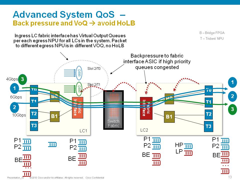
In this example T0 and T1 are receiving a total of 16G of traffic destined for T0 on the egress linecard. For a 10G port that is obviously too much.
T0 will flow off some of the traffic, depending on the queue, eventually signaling it back to the ingress linecard. While T0 on the ingress linecard also has some traffic for T1 on the egress LC (green), this traffic is not affected and continues to be sent to the destination port.
Resolution
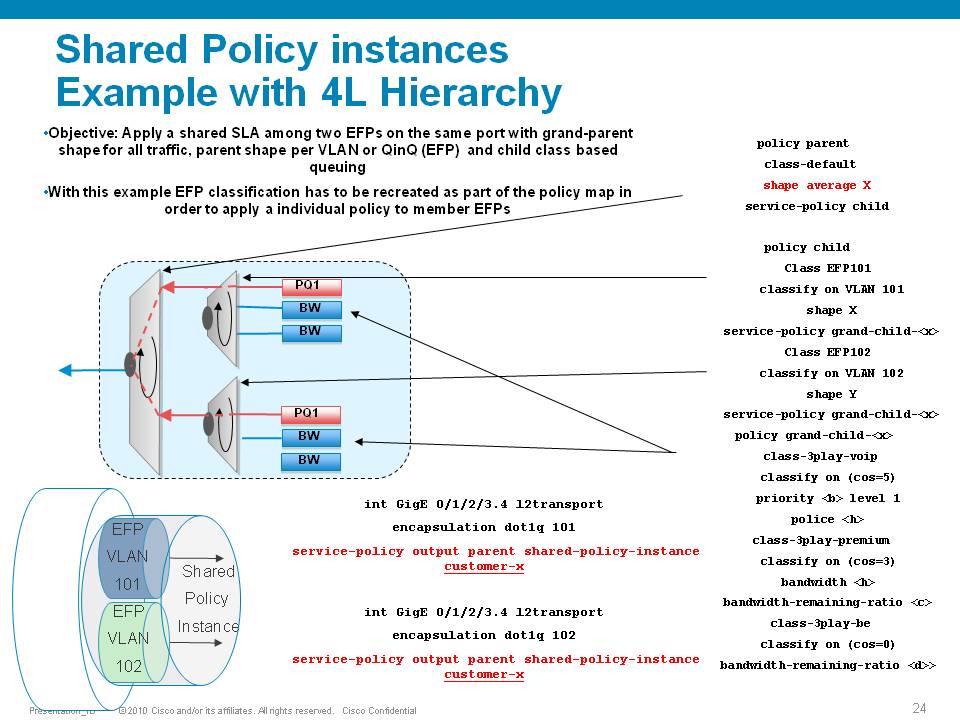
The ASR9000 has the ability of 4 levels of qos, a sample configuration and implemenation detail presented in this picture:
Policer having exceeddrops, not reaching configured rate
Set the Bc to CIR bps * (1 byte) / (8 bits) * 1.5 seconds
and
Be=2xBc
Default burst values are not optimal
Say you are allowing 1 pps, and then 1 second you don’t send anything, but the next second you want to send 2. in that second you’ll see an exceed, to visualize the problem.
Alternatively, Bc and Be can be configured in time units, e.g.:
policy-map OUT
class EF
police rate percent 25 burst 250 ms peak-burst 500 ms
For viewing the Bc and Be applied in hardware, run the "show qos interface interface [input|output]".
Why do I see non-zero values for Queue(conform) and Queue(exceed) in show policy-map commands?
On the ASR9k, every HW queue has a configured CIR and PIR value. These correspond to the "guaranteed" bandwidth for the queue, and the "maximum" bandwidth (aka shape rate) for the queue.
In some cases the user-defined QoS policy does NOT explicitly use both of these. However, depending on the exact QoS config the queueing hardware may require some nonzero value for these fields. Here, the system will choose a default value for the queue CIR. The "conform" counter in show policy-map is the number of packets/bytes that were transmitted within this CIR value, and the "exceed" value is the number of packets/bytes that were transmitted within the PIR value.
Note that "exceed" in this case does NOT equate to a packet drop, but rather a packet that is above the CIR rate on that queue.
You could change this behavior by explicitly configuring a bandwidth and/or a shape rate on each queue, but in general it's just easier to recognize that these counters don't apply to your specific situation and ignore them.
What is counted in QOS policers and shapers?
When we define a shaper in a qos pmap, the shaper takes the L2 header into consideration.
The shape rate defined of say 1Mbps would mean that if I have no dot1q or qinq, I can technically send more IP traffic then having a QIQ which has more L2 overhead. When I define a bandwidth statement in a class, same applies, also L2 is taken into consideration.
When defining a policer, it looks at L2 also.
In Ingress, for both policer & shaper, we use the incoming packet size (including the L2 header).
In order to account the L2 header in ingress shaper case, we have to use a TM overhead accounting feature, that will only let us add overhead in 4 byte granularity, which can cause a little inaccuracy.
In egress, for both policer & shaper we use the outgoing packet size (including the L2 header).
ASR9K Policer implementation supports 64Kbps granularity. When a rate specified is not a multiple of 64Kbps the rate would be rounded down to the next lower 64Kbps rate.
For policing, shaping, BW command for ingress/egress direction the following fields are included in the accounting.
|
MAC DA |
MAC SA |
EtherType |
VLANs.. |
L3 headers/payload |
CRC |
Port level shaping
Shaping action requires a queue on which the shaping is applied. This queue must be created by a child level policy. Typically shaper is applied at parent or grandparent level, to allow for differentiation between traffic classes within the shaper. If there is a need to apply a flat port-level shaper, a child policy should be configured with 100% bandwidth explicitly allocated to class-default.
Understanding show policy-map counters
QOS counters and show interface drops:
Policer counts are directly against the (sub)interface and will get reported on the "show interface" drops count.
The drop counts you see are an aggregate of what the NP has dropped (in most cases) as well as policer drops.
Packets that get dropped before the policer is aware of them are not accounted for by the policy-map policer drops but may
show under the show interface drops and can be seen via the show controllers np count command.
Policy-map queue drops are not reported on the subinterface drop counts.
The reason for that is that subinterfaces may share queues with each other or the main interface and therefore we don’t
have subinterface granularity for queue related drops.
Counters come from the show policy-map interface command
| Class name as per configuration | Class precedence6 | ||||||||
| Statistics for this class | Classification statistics (packets/bytes) (rate - kbps) | ||||||||
| Packets that were matched | Matched : 31583572/2021348608 764652 | ||||||||
| packets that were sent to the wire | Transmitted : Un-determined | ||||||||
| packets that were dropped for any reason in this class | Total Dropped : Un-determined | ||||||||
| Policing stats | Policing statistics (packets/bytes) (rate - kbps) | ||||||||
| Packets that were below the CIR rate | Policed(conform) : 31583572/2021348608 764652 | ||||||||
| Packets that fell into the 2nd bucket above CIR but < PIR | Policed(exceed) : 0/0 0 | ||||||||
| Packets that fell into the 3rd bucket above PIR | Policed(violate) : 0/0 0 | ||||||||
| Total packets that the policer dropped | Policed and dropped : 0/0 | ||||||||
| Statistics for Q'ing | Queueing statistics <<<---- | ||||||||
| Internal unique queue reference | Queue ID : 136 | ||||||||
|
how many packets were q'd/held at max one time (value not supported by HW) |
High watermark (Unknown) | ||||||||
|
number of 512-byte particles which are currently waiting in the queue |
Inst-queue-len (packets) : 4096 | ||||||||
|
how many packets on average we have to buffer (value not supported by HW) |
Avg-queue-len (Unknown) | ||||||||
|
packets that could not be buffered because we held more then the max length |
Taildropped(packets/bytes) : 31581615/2021223360 | ||||||||
| see description above (queue exceed section) | Queue(conform) : 31581358/2021206912 764652 | ||||||||
| see description above (queue exceed section) | Queue(exceed) : 0/0 0 | ||||||||
|
Packets subject to Randon Early detection and were dropped. |
RED random drops(packets/bytes) : 0/0 | ||||||||
Understanding the hardware qos output
RP/0/RSP0/CPU0:A9K-TOP#show qos interface g0/0/0/0 output
With this command the actual hardware programming can be verified of the qos policy on the interface
(not related to the output from the previous example above)
Tue Mar 8 16:46:21.167 UTC
Interface: GigabitEthernet0_0_0_0 output
Bandwidth configured: 1000000 kbps Bandwidth programed: 1000000
ANCP user configured: 0 kbps ANCP programed in HW: 0 kbps
Port Shaper programed in HW: 0 kbps
Policy: Egress102 Total number of classes: 2
----------------------------------------------------------------------
Level: 0 Policy: Egress102 Class: Qos-Group7
QueueID: 2 (Port Default)
Policer Profile: 31 (Single)
Conform: 100000 kbps (10 percent) Burst: 1248460 bytes (0 Default)
Child Policer Conform: TX
Child Policer Exceed: DROP
Child Policer Violate: DROP
----------------------------------------------------------------------
Level: 0 Policy: Egress102 Class: class-default
QueueID: 2 (Port Default)
----------------------------------------------------------------------
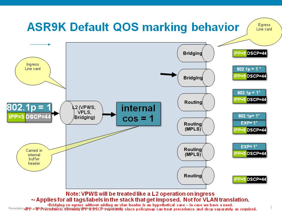
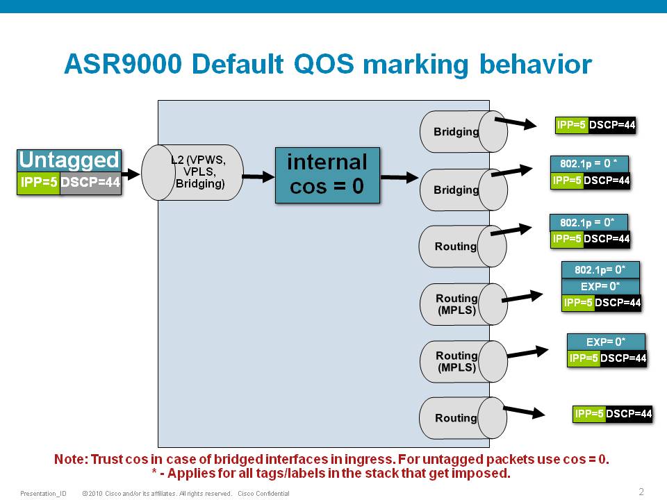
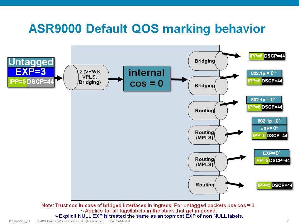
Default Marking behavior of the ASR9000
If you don't configure any service policies for QOS, the ASR9000 will set an internal cos value based on the IP Precedence, 802.1 Priority field or the mpls EXP bits.
Depending on the routing or switching scenario, this internal cos value will be used to do potential marking on newly imposed headers on egress.
Scenario 1
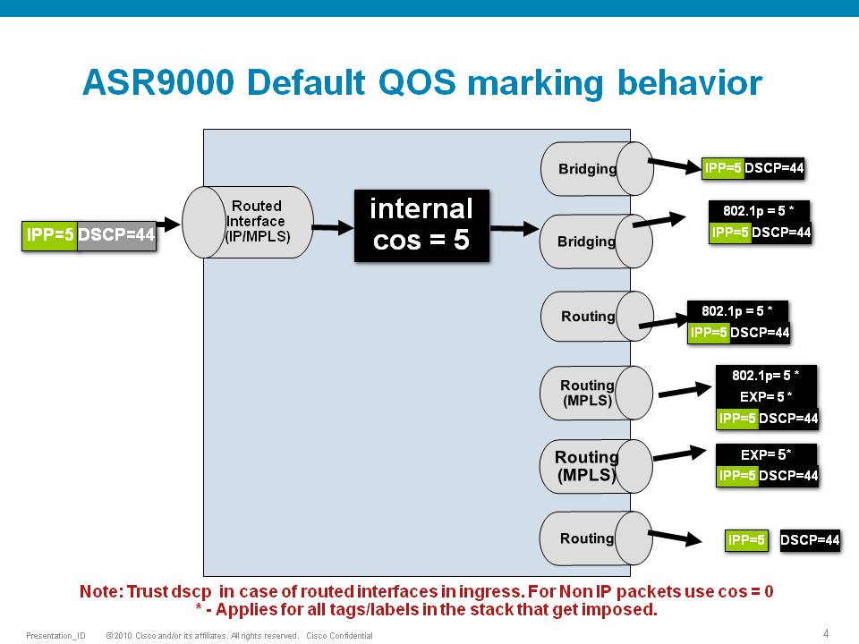
Scenario 2
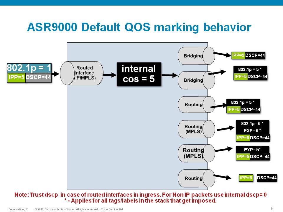
Scenario 3
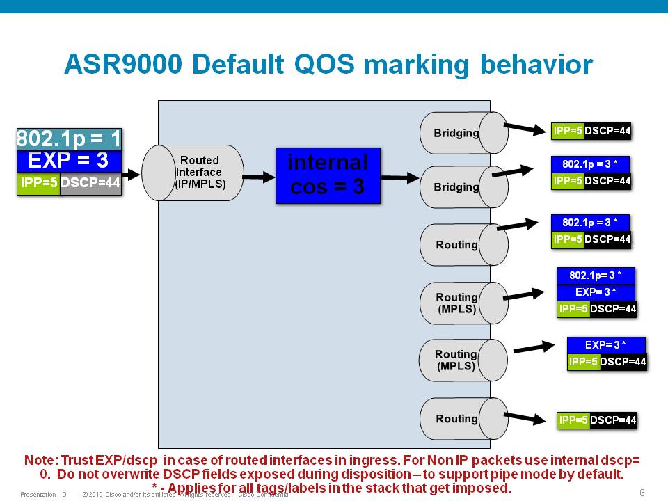
Scenario 4
Scenario 5
Scenario 6
Special consideration:
If the node is L3 forwarding, then there is no L2 CoS propagation or preservation as the L2 domain stops at the incoming interface and restarts at the outgoing interface.
Default marking PHB on L3 retains no L2 CoS information even if the incoming interface happened to be an 802.1q or 802.1ad/q-in-q sub interface.
CoS may appear to be propagated, if the corresponding L3 field (prec/dscp) used for default marking matches the incoming CoS value and so, is used as is for imposed L2 headers at egress.
If the node is L2 switching, then the incoming L2 header will be preserved unless the node has ingress or egress rewrites configured on the EFPs.
If an L2 rewrite results in new header imposition, then the default marking derived from the 3-bit PCP (as specified in 802.1p) on the incoming EFP is used to mark the new headers.
An exception to the above is that the DEI bit value from incoming 802.1ad / 802.1ah headers is propagated to imposed or topmost 802.1ad / 802.1ah headers for both L3 and L2 forwarding;
Related Information
ASR9000 Quality of Service configuration guide
Xander Thuijs, CCIE #6775
- Mark as Read
- Mark as New
- Bookmark
- Permalink
- Report Inappropriate Content
Hi, Xander
When packet comes in from a PW (VPWS or VPLS), it should be L2 packet after the label stack, which is non-IP packet. According to the statement "for non IP packet use internal DSCP=0. In such case, what is the value of dot1p COS in packet out to box2? Would it use the EXP or remains 0? Even for packet out of box1, it should be layer2 packet not ip packet, isn't it?
Thanks
- Mark as Read
- Mark as New
- Bookmark
- Permalink
- Report Inappropriate Content
Hello Xander,
Is the Backpressure mechanism invoked even on port-to-port basis when you have the egress interface policed/shaped below the physical limit of the interface?
e.g. you have 1G ingress interface with 800M incoming traffic and 1G egress interface shaped to 500M with HQoS serving outgoing traffic. Will the egress LC backpressure to ingress LC to drop packets on input and thus I need to put the important traffic into priority queues and drop best-effort packets?
What if the ingress and egress ports are on the same LC?
Thanks.
- Mark as Read
- Mark as New
- Bookmark
- Permalink
- Report Inappropriate Content
It is on a per "FIA" (fabric interface asic) bases. That means on the 24x10 you have 4 FIA's and on the 36x10 you have 6 of them.
each of them in that backpressure scenario gets lesser LC fabric access, meaning that instead of the 60G they want to push through, they can now only do 50G on the 24x10 for instance.
In other words the port groups 0-5, has one interface less to support, so if you need say 8 interfaces in use day one and want to protect against this, you want to wire/use them like 0-4 and then 6-9 (so skipping port 5).
regards
xander
- Mark as Read
- Mark as New
- Bookmark
- Permalink
- Report Inappropriate Content
Thank you for the explanation but now I am more confused than before :) I don't understand the example with wiring ports 0-4 instead of 0-5 - I thought if the FIA gets lesser fabric access, it will drop traffic from all ports equally, does not matter if there are 1 or 6 ports sending traffic to egress congested port. What difference does it make, if I wire only 5 ports on FIA?
Also, to get back to my initial question, will throttling by policing/shaping to less than physical speed on an interface trigger backpressure from egress to ingress FIA?
- Mark as Read
- Mark as New
- Bookmark
- Permalink
- Report Inappropriate Content
in a single RSP scenario, you have only 220G of access BW. For that reason all the FIA's are throttled back regardless of whether they have actual interface sending/receiving traffic. So if you only use 6 interfaces total, which connect to the same FIA, then these 6 interfaces can't get to their 60G of bw due to that single fabric in that scenario.
For that reason I am suggesting to use only 5 ports on that single FIA, so that they can send 50G of traffic no problemo. And then the sixth interface on a different FIA, then no one is getting back pressure.
oh, policing/shaping on egress to less then port speed will not push backpressure on the ingress FIA. regardless of whether you have single or dual rsp.
xander
- Mark as Read
- Mark as New
- Bookmark
- Permalink
- Report Inappropriate Content
Hi Xander,
We have some Trident LCs, where we are hitting a limit related to "L3 Entities". Could you help me understand what are "L3 Entities" and in what way we can prevent this from happen.
Any info would be great.
Regards,
PM
- Mark as Read
- Mark as New
- Bookmark
- Permalink
- Report Inappropriate Content
hi pedro,
L3 entities are parent level shapers. this may help:
Explicit MQC Policy-map level | Mapped to traffic manager entity | Comments |
Port-Shaping | L1 | Manages a physical port like GigabitEthernet/TenGigabitEthernet |
Grand-parent-level or Service-Fragment | L2 |
|
Parent-level | L3 |
|
Child-level/Flat policy | L4 |
|
Depending on the variant you have there are different scale limits per entity level (it is a q'ing asic restriction).
Line-card | Egress | Ingress | ||||||||
Version | Port Level (L0) | Grand-Parent | Parent | Child/Class Level (L4) | Port Level (L0) | Grand-Parent | Parent | Child/Class Level (L4) | ||
Extended | A9K-40GE-E | Port | 1 | 31 | 4k | 32k | 1 | 15 | 3.9k | 30k |
NPU | 10 | 310 | 8k | 64k | 10 | 150 | 3.9k | 30k | ||
LC | 40 | 1240 | 32k | 256k | 40 | 600 | 15.6k | 120k | ||
A9K-4T-E | Port | 1 | 255 | 4k | 32k | 1 | 63[1] | 4k | 32k | |
NPU | 1 | 255 | 4k | 32k | 1 | 6312 | 4k | 32k | ||
LC | 4 | 1020 | 16k | 128k | 4 | 25212 | 16k | 128k | ||
Base | A9K-40GE-B | Port | 1 | 31 | 1k | 8k | 1 | 15 | 1k | 8k |
NPU | 10 | 310 | 2k | 16k | 10 | 150 | 1k | 8k | ||
LC | 40 | 1240 | 8k | 64k | 40 | 600 | 4k | 32k | ||
A9K-4T-B | Port | 1 | 255 | 2k | 16k | 1 | 6312 | 1k | 8k | |
NPU | 1 | 255 | 2k | 16k | 1 | 63 | 1k | 8k | ||
LC | 4 | 1020 | 8k | 64k | 4 | 252 | 4k | 32k | ||
Low queue card | A9K-40GE-L | Port | 1 | 8 | 8 | 8 | 1 | 8 | 8 | 8 |
LC | 40 | 320 | 320 | 320 | 40 | 320 | 320 | 320 | ||
A9K-4T-L | port | 1 | 8 | 8 | 8 | 1 | 8 | 8 | 8 | |
LC | 4 | 8 | 32 | 32 | 4 | 32 | 32 | 32 | ||
regards
xander
- Mark as Read
- Mark as New
- Bookmark
- Permalink
- Report Inappropriate Content
Hi Xander,
Thanks for your prompt reply.
Another question, is there any command that allow me to know how many L3 Entities are consumed per NP (ideally per interface)? Also, in a bundle-ethernet with several L3 sub-interfaces, and each one of them with a diferent service-policy, how are L3 Entities consumed/allocated? I'm asking this since we don't have 1000K interfaces or sub-interfaces configured per NP but we are hitting the limits in some way...
Thanks,
Pedro
- Mark as Read
- Mark as New
- Bookmark
- Permalink
- Report Inappropriate Content
Hi Pedro,
The command you're looking for is:
sh qoshal resource summary np X location Y | b SUMMARY
- Mark as Read
- Mark as New
- Bookmark
- Permalink
- Report Inappropriate Content
Hello Xander,
I have question about marking. Do mentioned scenarios (1 to 6) apply based on physical ports or do they apply for logical ports if any?
We have situation where there are many L2 devices connected to ASR9K. ASR9K has ASR-MOD80-SE linecards with 1G and 10G MPA if it is of any meaning. Same L3 service is created on several of those L2 devices and interface BVI is used as L3 interface. All packets have CoS value set from L2 devices and have DSCP value set as well.
Here is sample configuration:
interface gig 0/0/0/0.100 l2transport
encapsulation dot1q 100
rewrite ingress tag pop 1 symmetric
interface ten 0/3/1/0.100 l2transport
encapsulation dot1q 100
rewrite ingress tag pop 1 symmetric
interface bvi 100
vrf test
ip address 1.1.1.1/24
l2vpn bridge group VLAN bridge-domain 100
interface gig 0/0/0/0.100
interface ten 0/3/1/0.100
routed interface bvi 100
Let's say 802.1p = 1 and DSCP = 44. Which value will be used by default for inner cos and for mpls exp on exiting L3 MPLS interface? Is ingress interface treated as L2 because of the pysical interface, or is ingress interface treated as L3 because of bvi interface?
Thank you,
Kice
- Mark as Read
- Mark as New
- Bookmark
- Permalink
- Report Inappropriate Content
Hi Kice,
you're hitting the scenario of bridging out a routed mpls interface.
this means that the internal COS will be 1 (based on the dot1p) and will result in an EXP of 1 on the mpls label header.
cheers
xander
- Mark as Read
- Mark as New
- Bookmark
- Permalink
- Report Inappropriate Content
Hi Xander/all,
Consider the scenario:
[CE1] --- [PE1] --- X --- [PE2] --- [CE2]
| |
+------[P3]-----+
CE1 and CE2 have a pseudowire stitching them together provisioned on PE1 and PE2 (LDP signalled)..
PE1 and PE2 have an RSVP MPLS TE tunnel along with a FRR tunnel via P3. In this scenario the PE1-PE2 link has failed so FRR is in play.
As per a configured policy, upon ingress from the CE, PE1 sets the topmost MPLS label EXP to 1.
P3 is has no explicit QoS policy configured.
Implicit-null is enabled on all P/PEs.
Upon egress from PE1 to P3, there are 2 labels:
- FRR (topmost)
- PWE (bottom)
(without implicit null we would have four (RSVP and LDP) sandwiched between FRR and PWE).
Question 1: What will be the EXP value of the PWE label? (remember the set mpls experimental command is using the topmost option).
Upon egress from P3 to PE2, there is one label (the FRR is popped):
- PWE (topmost)
Question 2: What will be the EXP value of the PWE label? Upon ingress P3 will set internal COS to 1 based on the FRR label - will the PWE label (now the topmost) have it's EXP set to 1 upon egress?
I wonder if this is a case for "set mpls experimental imposition" and/or explicit-null signalling.
Many thanks,
Scott
 - Emeritus")
- Mark as Read
- Mark as New
- Bookmark
- Permalink
- Report Inappropriate Content
Hi Scott,
if the QoS policy where set mpls experimental topmost is applied is an ingress policy on the PE1's interface facing the CE1, this set action will have no effect. You would have to use the set mpls experimental imposition. If using the 'imposition' in this scenario, all imposed labels will have the same MPLS EXP value.
if the QoS policy where set mpls experimental topmost is applied is an ingress policy on the PE1's interface facing the P3, only the FRR header will have the MPLS EXP set to 1.
P3 will pop the label and unless there is a QoS policy configured on its interfaces, it won't manipulate the MPLS EXP in the PWE header.
hth,
Aleksandar
- Mark as Read
- Mark as New
- Bookmark
- Permalink
- Report Inappropriate Content
HI Aleksandar,
thanks for the reply. It helps greatly.
On another topic (still QoS), what approach do you recommend for policing customer traffic on ingress to a 9K (via a 9KV) via a Bundle interface with two members?
If policing is configured on the Bundle then as I understand it the policy is pushed down to the member interfaces, meaning the theoretical limit increases by the number of members.
ie, police at 100Mb/s on the Bundle, both members police at 100Mb/s, allowing the customer to submit 200Mb/s (assuming the traffic hashes to both members).
Thanks,
Scott
- Mark as Read
- Mark as New
- Bookmark
- Permalink
- Report Inappropriate Content
Hi Scott,
your understanding is correct. In a distributed architecture when a QoS policy is applied to a bundle interface, one instance of the QoS policy is applied to each bundle member.
If bundles are deployed for redundancy, LACP can be configured to allow only one member to be active at the time. Alternatively, if this is a BNG deployment and the policer is applied on egress, you can configure load balancing to calculate the hash only based on the destination IP address (as opposed to 5-touple of src/dst IP, src/dst port and router ID).
If the bundle is deployed for bandwidth increase rather than for redundancy, there is no way to ensure that all traffic passes through a single instance of the QoS policy. In that scenario recommendation is to apply the QoS policy on a point in the network where it can really be enforced.
thanks,
Aleksandar
Find answers to your questions by entering keywords or phrases in the Search bar above. New here? Use these resources to familiarize yourself with the community: