- Cisco Community
- Technology and Support
- Networking
- Switching
- Two L3 switches as a redundant / mated pair
- Subscribe to RSS Feed
- Mark Topic as New
- Mark Topic as Read
- Float this Topic for Current User
- Bookmark
- Subscribe
- Mute
- Printer Friendly Page
- Mark as New
- Bookmark
- Subscribe
- Mute
- Subscribe to RSS Feed
- Permalink
- Report Inappropriate Content
11-07-2012 04:15 AM - edited 03-07-2019 09:54 AM
Hello, I hope someone can help me out here as I have been thrown a pile of hardware and been instructed to configure a redundant network from scratch, using my puny CCNA certified skills... :/
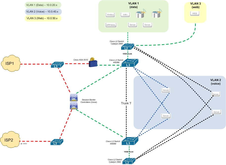
I have attached a diagram of what this network looks like, I just need to configure it to work!
So There are two Cisco 4900M L3 switches and two Cisco 2960 L2 switches. I need to configure the two L3 switches to operate as a redundant pair, as the servers connecting to them are connecting using bonded interfaces, which can only have one default gateway. So these two L3 switches need to have the same Vlan interface 1, 2 and 3 IP's set onto them.
How is this done? How are the two L3 switches made aware of each other? via a normal trunk? Is there some special configration for configuring a mated/redundant pair of switches? or are they both just configured as though they were the same switch, but linked?
Ive been reading up on VRRP, would this solution work for this?
Any help would be much appreciated, thanks!
Solved! Go to Solution.
- Labels:
-
Other Switching
Accepted Solutions
- Mark as New
- Bookmark
- Subscribe
- Mute
- Subscribe to RSS Feed
- Permalink
- Report Inappropriate Content
11-08-2012 08:28 AM
You can leave the trunk between two core switches but doing a port channel would be better for redundancy purposes.
With GLBP basically you'll need 3 IP's. I have mine configured with VLAN's like this:
Switch 1:
interface Vlan200
description MGMT
ip address 10.1.200.249 255.255.252.0
ip helper-address 192.168.0.2
glbp 200 ip 10.1.200.1
glbp 200 priority 110
glbp 200 preempt
glbp 200 weighting 5
glbp 200 load-balancing weighted
glbp 200 authentication md5 key-string 7 ***********
glbp 200 weighting track 200 decrement 20
end
Switch 2:
interface Vlan200
ip address 10.1.200.250 255.255.252.0
ip helper-address 192.168.0.2
glbp 200 ip 10.1.200.1
glbp 200 preempt
glbp 200 weighting 6
glbp 200 load-balancing weighted
glbp 200 authentication md5 key-string 7 ***********
glbp 200 weighting track 200 decrement 20
end
Here are some good links and a really awesome cheat sheet: I know there is a whole lot of information but trust me it is better to have more information then less , if you implement you also need to know how to troubleshoot it as well. Depending on your Network configuration you also will need to consider STP behavior.
http://packetlife.net/media/library/3/First_Hop_Redundancy.pdf
http://www.cisco.com/en/US/docs/solutions/Enterprise/Campus/HA_campus_DG/hacampusdg.html#wp1108489
http://blog.ine.com/tag/load-balancing/
http://www.ciscozine.com/2008/11/18/configuring-redundancy-with-glbp/
http://www.cisco.com/en/US/docs/ios/12_2t/12_2t15/feature/guide/ft_glbp.html#wp1027173
http://cisconinja.wordpress.com/category/hsrp-vrrp-and-glbp/
- Mark as New
- Bookmark
- Subscribe
- Mute
- Subscribe to RSS Feed
- Permalink
- Report Inappropriate Content
11-07-2012 04:50 AM
Hi
i think you need HSRP or VRRP, yes, this should work.
There should be a trunk between the l3 switches, and you ll need to configure each vlan with and ip address and a standby ip adress plus a standby priority.
Also on layer 2 best practise is to make the switch with the highest HSRP priority also make root bridge for that vlan.
I do not have much time right now, but i could sketch a setup example for you tomorrow.
- Mark as New
- Bookmark
- Subscribe
- Mute
- Subscribe to RSS Feed
- Permalink
- Report Inappropriate Content
11-07-2012 05:16 AM
Hi Ton V, thanks alot, looks like VRRP is the answer, not just have to work out how to implement it! An example would be great.
- Mark as New
- Bookmark
- Subscribe
- Mute
- Subscribe to RSS Feed
- Permalink
- Report Inappropriate Content
11-07-2012 05:04 AM
VRRP should work fine with a trunk between the switches
Here is sample config you can use:
switch-1
interface Vlan10
ip address 10.10.10.1 255.255.255.0
vrrp 10 ip 10.10.10.3
vrrp 10 priority 120
end
switch-2
interface Vlan10
ip address 10.10.10.2 255.255.255.0
vrrp 10 ip 10.10.10.3
end
in this case switch-1 has a higher priority, so it is the active device
HTH
- Mark as New
- Bookmark
- Subscribe
- Mute
- Subscribe to RSS Feed
- Permalink
- Report Inappropriate Content
11-07-2012 05:17 AM
Hi Reza, thanks for this. So hosts on the network on vlan 10 would be set with the default gateway of 10.10.10.3?
- Mark as New
- Bookmark
- Subscribe
- Mute
- Subscribe to RSS Feed
- Permalink
- Report Inappropriate Content
11-07-2012 05:24 AM
Hi, default gateway of 10.10.10.3 yes, that is correct
In this example, switch 1 is VRRP master for vlan 10.
Make sure that the switch 1 will be root of this vlan at layer 2 by setting the spanning tree priority (low)
Make sure switch 2 has a higher priority than switch 1 on l2, but lower than the other switches.
Repeat this for each vlan, and make switch 2 master for the next vlan, then switch 1 master for another next vlan etc
That way you ll have load share on both links.
- Mark as New
- Bookmark
- Subscribe
- Mute
- Subscribe to RSS Feed
- Permalink
- Report Inappropriate Content
11-07-2012 05:36 AM
Ok I will give this a try. I dont think bandwidth will be an issue as this is all on a 10Gb switching platform, so we dont need to load balance specifically, but I will keep that option in mind incase its required. Currrently I just want to get the redundancy working
- Mark as New
- Bookmark
- Subscribe
- Mute
- Subscribe to RSS Feed
- Permalink
- Report Inappropriate Content
11-07-2012 05:49 AM
with few vlans, you don't to worry about load balancing. Keep it simple with one switch as the active and root and the other stand-by and backup root for all vlans.
HTH
- Mark as New
- Bookmark
- Subscribe
- Mute
- Subscribe to RSS Feed
- Permalink
- Report Inappropriate Content
11-07-2012 05:23 AM
Another question, I intend to have all the servers on Vlan 1 and Vlan 3 (in the diagram) also connected to each L2 switch via bonded interfaces. Does the same vrrp config get applied to each Vlan interface?
So for example like this? (ive adjusted the vlans to match mine currently setup)
switch-1
interface Vlan1
ip address 10.10.10.1 255.255.255.0
vrrp 10 ip 10.10.10.3
vrrp 10 priority 120
end
interface Vlan2
ip address 10.10.20.1 255.255.255.0
vrrp 10 ip 10.10.20.3
vrrp 10 priority 120
end
interface Vlan3
ip address 10.10.30.1 255.255.255.0
vrrp 10 ip 10.10.30.3
vrrp 10 priority 120
end
switch-2
interface Vlan1
ip address 10.10.10.2 255.255.255.0
vrrp 10 ip 10.10.10.3
end
interface Vlan2
ip address 10.10.20.2 255.255.255.0
vrrp 10 ip 10.10.20.3
end
interface Vlan3
ip address 10.10.30.2 255.255.255.0
vrrp 10 ip 10.10.30.3
end
- Mark as New
- Bookmark
- Subscribe
- Mute
- Subscribe to RSS Feed
- Permalink
- Report Inappropriate Content
11-07-2012 07:34 AM
Unless you have multiple vendors instead of VRRP I think you should use GLBP. Both switches will be Active/Active with GLBP.
Setup a port channel between the two core switches using the ten gig ports.
Now on the 2960 diagram shows 10Gig Trunk. 2960's do not have a 10Gig port.
- Mark as New
- Bookmark
- Subscribe
- Mute
- Subscribe to RSS Feed
- Permalink
- Report Inappropriate Content
11-08-2012 01:41 AM
Hi Mohammad, thanks ill have a look at that. Sorry for the confusion thats a mistake on the diagram, they are 1Gb trunks.
- Mark as New
- Bookmark
- Subscribe
- Mute
- Subscribe to RSS Feed
- Permalink
- Report Inappropriate Content
11-08-2012 03:24 AM
Hi Mohammad, after a bit of review, I think you are right it is best that I use GLBP, as the switches will in fact need to be in an active/active state for the bonded interfaces to work. Is the config basically the same as VRRP? Is a port channel between the switches required or will the currently configured trunk between them work?
Could I please ask for a simple example config for this so I can get my head around it? Would be much appreciated!
- Mark as New
- Bookmark
- Subscribe
- Mute
- Subscribe to RSS Feed
- Permalink
- Report Inappropriate Content
11-08-2012 08:28 AM
You can leave the trunk between two core switches but doing a port channel would be better for redundancy purposes.
With GLBP basically you'll need 3 IP's. I have mine configured with VLAN's like this:
Switch 1:
interface Vlan200
description MGMT
ip address 10.1.200.249 255.255.252.0
ip helper-address 192.168.0.2
glbp 200 ip 10.1.200.1
glbp 200 priority 110
glbp 200 preempt
glbp 200 weighting 5
glbp 200 load-balancing weighted
glbp 200 authentication md5 key-string 7 ***********
glbp 200 weighting track 200 decrement 20
end
Switch 2:
interface Vlan200
ip address 10.1.200.250 255.255.252.0
ip helper-address 192.168.0.2
glbp 200 ip 10.1.200.1
glbp 200 preempt
glbp 200 weighting 6
glbp 200 load-balancing weighted
glbp 200 authentication md5 key-string 7 ***********
glbp 200 weighting track 200 decrement 20
end
Here are some good links and a really awesome cheat sheet: I know there is a whole lot of information but trust me it is better to have more information then less , if you implement you also need to know how to troubleshoot it as well. Depending on your Network configuration you also will need to consider STP behavior.
http://packetlife.net/media/library/3/First_Hop_Redundancy.pdf
http://www.cisco.com/en/US/docs/solutions/Enterprise/Campus/HA_campus_DG/hacampusdg.html#wp1108489
http://blog.ine.com/tag/load-balancing/
http://www.ciscozine.com/2008/11/18/configuring-redundancy-with-glbp/
http://www.cisco.com/en/US/docs/ios/12_2t/12_2t15/feature/guide/ft_glbp.html#wp1027173
http://cisconinja.wordpress.com/category/hsrp-vrrp-and-glbp/
- Mark as New
- Bookmark
- Subscribe
- Mute
- Subscribe to RSS Feed
- Permalink
- Report Inappropriate Content
11-08-2012 01:30 PM
Wow thanks really appreciate that.
I went ahead and tried configuring it before I saw your reply, and got it working, using a very basic GLBP setup. Only tried it with one VLAN so far and it works fine, each cable whiCh connects to a seperate L3 switch, from the bonded pair from a server can be disconnected and the server keeps a connection to the rest of the network and internet just fine, which is the main thing. here is what I used;
Switch 1
interface Vlan2
description VOICE
ip address 10.0.40.248 255.255.255.0
glbp 20 ip 10.0.40.247
glbp 20 priority 120
Switch 2
interface Vlan2
description VOICE
ip address 10.0.40.249 255.255.255.0
glbp 20 ip 10.0.40.247
You seem to have a much more elaborate config, im just glad its working for now but do you see anything wrong/potential problems with the way I set it ? I will read you links and probably find out for myself soon anyway
- Mark as New
- Bookmark
- Subscribe
- Mute
- Subscribe to RSS Feed
- Permalink
- Report Inappropriate Content
11-08-2012 02:43 PM
With fewer settings lot of stuff is default so in your case load balancing method is round robin, you might want to add the preempt command so the gateway can take over as AVG if the priority changes.
Discover and save your favorite ideas. Come back to expert answers, step-by-step guides, recent topics, and more.
New here? Get started with these tips. How to use Community New member guide
