- Cisco Community
- Technology and Support
- Wireless - Mobility
- Wireless - Mobility Knowledge Base
- Cisco 2112 Wireless LAN Controller and Apple TV Airplay
- Subscribe to RSS Feed
- Mark as New
- Mark as Read
- Bookmark
- Subscribe
- Printer Friendly Page
- Report Inappropriate Content
- Subscribe to RSS Feed
- Mark as New
- Mark as Read
- Bookmark
- Subscribe
- Printer Friendly Page
- Report Inappropriate Content
12-28-2011 04:43 AM - edited 11-18-2020 02:56 AM
Introduction
Cisco 2112 Wireless LAN Controller and Apple TV Airplay
Scenario
Trouble using iTunes, iPhones and iPads in Wireless LAN (2112 WLC and 1142N W AP's). During network scan, Apple TV is visible with port 5353 open, which is Apple's Bonjour service.
However while playing music/video in iTunes or on an iPhone/iPad, Airplay icon is not available/visible. Once connected to LAN, the Airplay icon appears immediately.
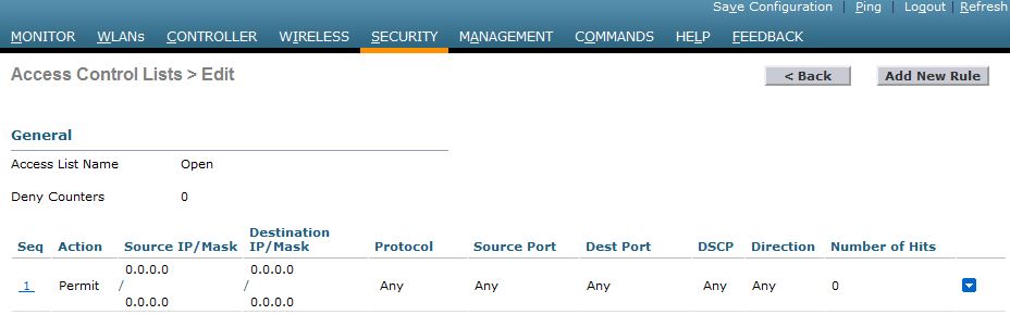
Created an allow all rule in the ACL but no change.
Solution
- We need to make sure that all the devices MUST be on the same SUBNET. for e.g. IP of the Apple TV is 192.168.200.x and the iPhone is 192.168.200.x.
- Multicast needs to be enabled i.e. enable Multi-cast in Controller > Multicast > Global Multicast Mode.
- Set the multicast address should made the Airplay icon appear immediately.


More Information - Configuring Multicast Mode
If your network supports packet multicasting, you can configure the multicast method that the controller uses. The controller performs multicasting in two modes:
•Unicast mode—In this mode, the controller unicasts every multicast packet to every access point associated to the controller. This mode is inefficient but might be required on networks that do not support multicasting.
•Multicast mode—In this mode, the controller sends multicast packets to a CAPWAP multicast group. This method reduces overhead on the controller processor and shifts the work of packet replication to your network, which is much more efficient than the unicast method.
You can enable multicast mode using the controller GUI or CLI.
Understanding Multicast Mode
When you enable multicast mode and the controller receives a multicast packet from the wired LAN, the controller encapsulates the packet using CAPWAP and forwards the packet to the CAPWAP multicast group address. The controller always uses the management interface for sending multicast packets. Access points in the multicast group receive the packet and forward it to all the BSSIDs mapped to the interface on which clients receive multicast traffic. From the access point perspective, the multicast appears to be a broadcast to all SSIDs.
In controller software release 4.2 or later releases, Internet Group Management Protocol (IGMP) snooping is introduced to better direct multicast packets. When this feature is enabled, the controller gathers IGMP reports from the clients, processes them, creates unique multicast group IDs (MGIDs) from the IGMP reports after selecting the Layer 3 multicast address and the VLAN number, and sends the IGMP reports to the infrastructure switch. The controller sends these reports with the source address as the interface address on which it received the reports from the clients. The controller then updates the access point MGID table on the access point with the client MAC address. When the controller receives multicast traffic for a particular multicast group, it forwards it to all the access points, but only those access points that have active clients listening or subscribed to that multicast group send multicast traffic on that particular WLAN. IP packets are forwarded with an MGID that is unique for an ingress VLAN and the destination multicast group. Layer 2 multicast packets are forwarded with an MGID that is unique for the ingress interface.
When IGMP snooping is disabled, the following is true:
•The controller always uses Layer 2 MGID when it sends multicast data to the access point. Every interface created is assigned one Layer 2 MGID. For example, the management interface has an MGID of 0, and the first dynamic interface created is assigned an MGID of 8, which increments as each dynamic interface is created.
•The IGMP packets from clients are forwarded to the router. As a result, the router IGMP table is updated with the IP address of the clients as the last reporter.
When IGMP snooping is enabled, the following is true:
•The controller always uses Layer 3 MGID for all Layer 3 multicast traffic sent to the access point. For all Layer 2 multicast traffic, it continues to use Layer 2 MGID.
•IGMP report packets from wireless clients are consumed or absorbed by the controller, which generates a query for the clients. After the router sends the IGMP query, the controller sends the IGMP reports with its interface IP address as the listener IP address for the multicast group. As a result, the router IGMP table is updated with the controller IP address as the multicast listener.
•When the client that is listening to the multicast groups roams from one controller to another, the first controller transmits all the multicast group information for the listening client to the second controller. As a result, the second controller can immediately create the multicast group information for the client. The second controller sends the IGMP reports to the network for all multicast groups to which the client was listening. This process aids in the seamless transfer of multicast data to the client.
•If the listening client roams to a controller in a different subnet, the multicast packets are tunneled to the anchor controller of the client to avoid the reverse path filtering (RPF) check. The anchor then forwards the multicast packets to the infrastructure switch.
Note
The MGIDs are controller specific. The same multicast group packets coming from the same VLAN in two different controllers may be mapped to two different MGIDs.
Note
If Layer 2 multicast is enabled, a single MGID is assigned to all the multicast addresses coming from an interface (see Figure 4-26).
Guidelines for Using Multicast Mode
Follow these guidelines when you enable multicast mode on your network:
•The Cisco Unified Wireless Network solution uses some IP address ranges for specific purposes, and you should keep these ranges in mind when configuring a multicast group:
–224.0.0.0 through 224.0.0.255—Reserved link local addresses
–224.0.1.0 through 238.255.255.255—Globally scoped addresses
–239.0.0.0 through 239.255.x.y /16—Limited scope addresses
•When you enable multicast mode on the controller, you also must configure a CAPWAP multicast group address. Access points subscribe to the CAPWAP multicast group using IGMP.
•Cisco 1100, 1130, 1200, 1230, and 1240 access points use IGMP versions 1, 2, and 3.
•Access points in monitor mode, sniffer mode, or rogue detector mode do not join the CAPWAP multicast group address.
•The CAPWAP multicast group configured on the controllers should be different for different controllers.
•Multicast mode does not operate across intersubnet mobility events such as guest tunneling. It does, however, operate with interface overrides using RADIUS (but only when IGMP snooping is enabled) and with site-specific VLANs (access point group VLANs).
•For LWAPP, the controller drops multicast packets sent to UDP control port 12223. For CAPWAP, the controller drops multicast packets sent to UDP control and data ports 5246 and 5247, respectively. Therefore, you may want to consider not using these port numbers with the multicast applications on your network.
•We recommend that any multicast applications on your network not use the multicast address configured as the CAPWAP multicast group address on the controller.
•Cisco 2100 Series Controllers do not support multicast-unicast mode. They do, however, support multicast-multicast mode, except when access points are connected directly to the local port of a 2100 series controller.
Using the GUI to Enable Multicast Mode
To enable multicast mode using the controller GUI, follow these steps:
Step 1 Choose Controller > Multicast to open the Multicast page, see Figure.
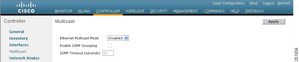
Step 2 Choose one of the following options from the Ethernet Multicast Mode drop-down list:
•Disabled—Disables multicasting on the controller. This is the default value.
•Unicast—Configures the controller to use the unicast method to send multicast packets.
•Multicast—Configures the controller to use the multicast method to send multicast packets to a CAPWAP multicast group.
Note Hybrid REAP supports unicast mode only.
Step 3 If you chose Multicast in Step 2, enter the IP address of the multicast group in the Multicast Group Address text box.
Step 4 If you want to enable IGMP snooping, select the Enable IGMP Snooping check box. If you want to disable IGMP snooping, leave the check box unselected. The default value is disabled.
Step 5 To set the IGMP timeout, enter a value between 30 and 7200 seconds in the IGMP Timeout text box. The controller sends three queries in one timeout value at an interval of timeout/3 to see if any clients exist for a particular multicast group. If the controller does not receive a response through an IGMP report from the client, the controller times out the client entry from the MGID table. When no clients are left for a particular multicast group, the controller waits for the IGMP timeout value to expire and then deletes the MGID entry from the controller. The controller always generates a general IGMP query (that is, to destination address 224.0.0.1) and sends it on all WLANs with an MGID value of 1.
Step 6 Click Apply to commit your changes.
Step 7 Click Save Configuration to save your changes.
Reference links
This document was generated from the following discussion: Cisco 2112 Wireless LAN Controller and Apple TV Airplay
Cisco Wireless LAN Controller Configuration Guide, Release 7.0 - Configuring Controller Settings
Guidelines for Using Multicast Mode
- Mark as Read
- Mark as New
- Bookmark
- Permalink
- Report Inappropriate Content
Controller > General
AP Multicast Mode: Multicast:
Multicast Group Address : 239.255.255.1
Controller > Multicast:
Enable Global Multicast Mode: Checked
Enable IGMP Snooping: Checked
http://www.cisco.com/en/US/docs/wireless/controller/7.0/configuration/guide/c70ccfg.html#wp1088037
Find answers to your questions by entering keywords or phrases in the Search bar above. New here? Use these resources to familiarize yourself with the community: