- Cisco Community
- Technology and Support
- Networking
- Networking Knowledge Base
- Reading and Understanding the OSPF Database
- Subscribe to RSS Feed
- Mark as New
- Mark as Read
- Bookmark
- Subscribe
- Printer Friendly Page
- Report Inappropriate Content
- Subscribe to RSS Feed
- Mark as New
- Mark as Read
- Bookmark
- Subscribe
- Printer Friendly Page
- Report Inappropriate Content
04-03-2013 02:59 AM - edited 03-01-2019 04:54 PM
Introduction
OSPF, being a link-state protocol, allows for every router in the network to know of every link and OSPF speaker in the entire network. From this picture each router independently runs the Shortest Path First (SPF) algorithm to determine the best path through the network. All of this information is stored in the "Link State Database" (LSDB). Every network engineer has seen the LSDB at some point by running show ip ospf database but few actually know how to read the details. By looking only at the LSDB we should have enough information to draw a topology diagram from scratch.
Link State Advertisements
OSPF uses "Link State Advertisements" (LSAs) to provide information about links and link-costs to neighboring OSPF speakers. OSPF defines multiple LSAs, which all serve a different purpose.
| LSA Type | Who Generates the LSA? | What is Accomplished? |
|---|---|---|
Type 1 - Router LSA | Every router in every area | How routers advertise their connected interfaces |
Type 2 - Network LSA | DRs on all non-point-to-point links | The DR collects all the Type 1 LSAs and sends out a single Type 2 representing all of the routers on the link. This is used to build the Shortest Path Tree |
Type 3 - Network Summary LSA | Area Border Routers (ABRs) | ABRs send a single LSA representing all of the Type 1 and Type 2 LSAs in an area. This reduces the number of LSAs on the routers in other areas. |
Type 4 - ASBR Summary LSA | ABRs connected to an area where external routes (Type 5) are originated | Type 4 LSAs are sent to other areas to build the Shortest Path Tree to an ASBR. |
Type 5 - AS External LSA | Routers with the redistribute command that are not in a NSSA area | This represents any external routes redistributed into OSPF. |
Type 7 - NSSA External LSA | Routers with the redistribute command that are in a NSSA area | Type 5 LSAs are not allowed in Stub Areas. Type 7 LSAs allow external information to pass through NSSA areas. |
Building the Topology
Starting on a router named r120 we can get a high level overview of the network (or at least our Area).
First, who are we (what is our Router ID)?
r120#show ip ospf data
OSPF Router with ID (10.0.0.120) (Process ID 1)
Next, who are the other routers in our area?
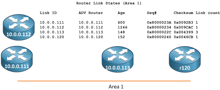
Router Link States (Area 1)
Link ID ADV Router Age Seq# Checksum Link count
10.0.0.111 10.0.0.111 600 0x8000023A 0x0092B3 1
10.0.0.112 10.0.0.112 1246 0x80000234 0x009CAC 1
10.0.0.113 10.0.0.113 148 0x8000022C 0x004399 3
10.0.0.120 10.0.0.120 152 0x80000240 0x0046CB 1
This tells us there are four routers in Area 1. The router with RID 10.0.0.113 has 3 links in Area 1, every one else has only 1 link.
Next, who are all of the DRs in this Area? What network segments do they represent?
Net Link States (Area 1)
Link ID ADV Router Age Seq# Checksum
192.168.1.112 10.0.0.112 1862 0x80000237 0x00D860
192.168.7.113 10.0.0.113 12 0x80000001 0x00E8F5
Routers 10.0.0.112 and 10.0.0.113 are the router IDs of the DRs for two segments. 192.168.1.112 and 192.168.7.113 represent the IP address of the DR on that segment. We will see later that if we were to look at the Router LSA for 10.0.0.112, for example, we would see 192.168.1.112 as one of the interfaces owned by that router.
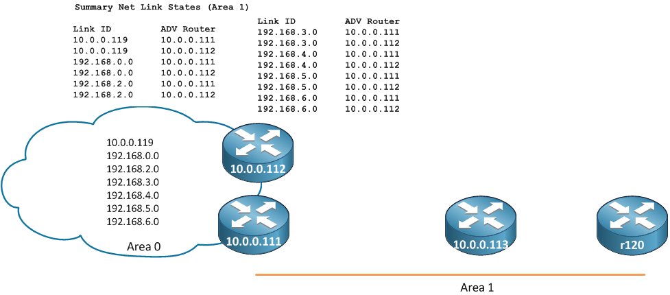
The Summary Network LSAs (Type 3) are generated by the ABRs and will give us information about every segment in the network, outside of our Area. Type 1 and Type 2 LSAs are not flooded beyond an ABR. The ABR is responsible for taking all of the information in Type 1 and Type 2 LSAs and repackaging them into Type 3 LSAs.
Summary Net Link States (Area 1)
Link ID ADV Router Age Seq# Checksum
10.0.0.119 10.0.0.111 1215 0x8000022A 0x00A845
10.0.0.119 10.0.0.112 1862 0x80000229 0x00A449
192.168.0.0 10.0.0.111 1215 0x80000234 0x00D842
192.168.0.0 10.0.0.112 1862 0x80000233 0x00D446
192.168.2.0 10.0.0.111 1215 0x80000234 0x0027E7
192.168.2.0 10.0.0.112 1862 0x80000233 0x0023EB
192.168.3.0 10.0.0.111 1215 0x80000232 0x008481
192.168.3.0 10.0.0.112 1862 0x80000232 0x007E86
192.168.4.0 10.0.0.111 1215 0x80000232 0x00798B
192.168.4.0 10.0.0.112 1862 0x80000232 0x007390
192.168.5.0 10.0.0.111 1215 0x80000232 0x006E95
192.168.5.0 10.0.0.112 1862 0x80000232 0x00689A
192.168.6.0 10.0.0.111 1215 0x80000231 0x00C930
192.168.6.0 10.0.0.112 1862 0x80000231 0x00C335
From this we know Area 1 has two ABRs with RIDs 10.0.0.111 and 10.0.0.112. We also see a total of 7 segments in the entire OSPF network. Each network is seen twice because each ABR generates its own LSA. Two ABRs means two LSAs.
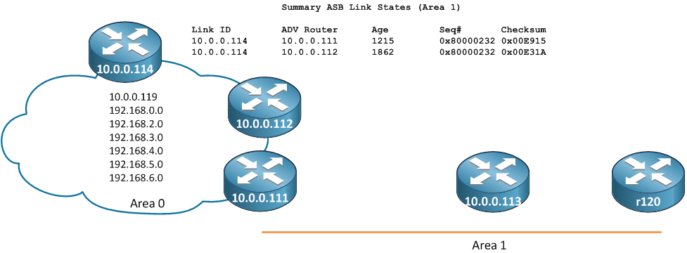
Type 4, Summary Network LSAs are next. These are generated by the ABRs (10.0.0.111 and 10.0.0.112) to represent any routers or ABRs outside of our Area that is passing along Type 5 (external LSAs). This may be a little confusing at this point but it will make more sense when we start working through the topology.
Summary ASB Link States (Area 1)
Link ID ADV Router Age Seq# Checksum
10.0.0.114 10.0.0.111 1215 0x80000232 0x00E915
10.0.0.114 10.0.0.112 1862 0x80000232 0x00E31A
Finally the external routes are represented by Type 5 LSAs.
Type-5 AS External Link States
Link ID ADV Router Age Seq# Checksum Tag
172.16.0.113 10.0.0.113 631 0x80000001 0x00F006 0
172.16.0.118 10.0.0.114 678 0x80000001 0x009775 0
Here we see two different prefixes being redistributed into OSPF. The ADV Router is either the configured with the redistribute command (10.0.0.113) or an ABR connected to a NSSA area where redistribution is happening.
With this information let's build some high level topologies. First, start with what we know from the Type 1 LSAs (all the routers in our area)
We will skip the Type 2 Network LSAs for now and go to the Type 3 Summary Network LSAs. This gives us the other subnets in the network and the ABRs for Area 1
The Type 4 ASBR Summary LSAs let us know that 10.0.0.114 is also an ABR on Area 0
and finally, the Type 5's tell us about the externals. Using the "ADV Router" field we can figure out where those routes come from.
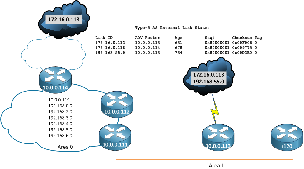
Just from looking at the summary information in the database we've been able to put a lot of information together. Now we can start looking into the LSAs to get an idea of what the connectivity of Area 1 looks like.
We will start with router r120. Since we don't know anything about the links r120 has, we start with a router with no connections.

To see the connections on r120 we'll need to look at the Router LSA that is generated by r120 (remember: Router LSAs are represented by the Router ID)
r120#show ip ospf database router 10.0.0.120
OSPF Router with ID (10.0.0.120) (Process ID 1)
Router Link States (Area 1)
LS age: 408
Options: (No TOS-capability, DC)
LS Type: Router Links
Link State ID: 10.0.0.120
Advertising Router: 10.0.0.120
LS Seq Number: 8000023C
Checksum: 0x815
Length: 36
Number of Links: 1
Link connected to: a Transit Network
(Link ID) Designated Router address: 192.168.7.113
(Link Data) Router Interface address: 192.168.7.120
Number of MTID metrics: 0
TOS 0 Metrics: 10
From this we know a few things:
1.) There is a single interface with IP 192.168.7.120
2.) There is a least one other router on this segment with IP 192.168.7.113, and this is the DR
2a.) Because there is a DR, we know this interface is multi-access (not point-to-point)
3.) The Router ID (10.0.0.120) is not advertised in OSPF (becuase there is no link information representing the router ID)
4.) The metric we are advertising is 10
We have an IP and a DR, but we don't know the subnet mask or which router in Area 1 owns the DR IP address. There is where the Type 2 LSA comes in. Remember the Type 2 is generated by the DR for a segment, and represents that segment, so we look for the segment DR.
r120#show ip ospf data network 192.168.7.113
OSPF Router with ID (10.0.0.120) (Process ID 1)
Net Link States (Area 1)
Routing Bit Set on this LSA in topology Base with MTID 0
LS age: 93
Options: (No TOS-capability, DC)
LS Type: Network Links
Link State ID: 192.168.7.113 (address of Designated Router)
Advertising Router: 10.0.0.113
LS Seq Number: 80000004
Checksum: 0xE2F8
Length: 32
Network Mask: /24
Attached Router: 10.0.0.113
Attached Router: 10.0.0.120
A lot of great information here. First, we see the advertising router, which is the Router ID of the DR. In this case it's 10.0.0.113. Now we know who r120 is attached to. We also see the network mask (/24) and all of the routers on the segment. In this case only r120 and 10.0.0.113 are on the segment. If there were other routers on this segment we would see their Router IDs in the "Attached Router" list. So let's update the topology diagram.
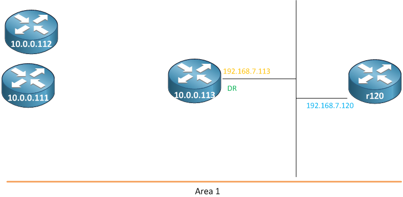
Now we can look at the Router LSA of 10.0.0.113
r120#show ip ospf data router 10.0.0.113
OSPF Router with ID (10.0.0.120) (Process ID 1)
Router Link States (Area 1)
Routing Bit Set on this LSA in topology Base with MTID 0
LS age: 395
Options: (No TOS-capability, DC)
LS Type: Router Links
Link State ID: 10.0.0.113
Advertising Router: 10.0.0.113
LS Seq Number: 80000256
Checksum: 0x5465
Length: 60
AS Boundary Router
Number of Links: 3
Link connected to: a Stub Network
(Link ID) Network/subnet number: 10.0.0.113
(Link Data) Network Mask: 255.255.255.255
Number of MTID metrics: 0
TOS 0 Metrics: 1
Link connected to: a Transit Network
(Link ID) Designated Router address: 192.168.7.113
(Link Data) Router Interface address: 192.168.7.113
Number of MTID metrics: 0
TOS 0 Metrics: 10
Link connected to: a Transit Network
(Link ID) Designated Router address: 192.168.1.112
(Link Data) Router Interface address: 192.168.1.113
Number of MTID metrics: 0
TOS 0 Metrics: 10
Here we see three interfaces: 10.0.0.113, 192.168.7.113 and 192.168.1.113. We see that 10.0.0.113 is a "Stub Network". This does not have any relationship to a Stub Area, a "stub network" is simply an interface with no OSPF neighbors on it. We can also see that we are not the DR on the segment for 192.168.1.113. Let's take a look at the Type 2 for that segment. Remember, the Type 2 is represented by the DR for that segment.
r120#show ip ospf data network 192.168.1.112
OSPF Router with ID (10.0.0.120) (Process ID 1)
Net Link States (Area 1)
Routing Bit Set on this LSA in topology Base with MTID 0
LS age: 161
Options: (No TOS-capability, DC)
LS Type: Network Links
Link State ID: 192.168.1.112 (address of Designated Router)
Advertising Router: 10.0.0.112
LS Seq Number: 80000261
Checksum: 0x848A
Length: 36
Network Mask: /24
Attached Router: 10.0.0.112
Attached Router: 10.0.0.111
Attached Router: 10.0.0.113
We know that routers 10.0.0.112, 10.0.0.111 and 10.0.0.113 are all attached to this segment. Now we can look at the Router LSAs for routers 10.0.0.112 and 10.0.0.111. This will provide us with their interface IPs as well as any Stub Networks we haven't seen yet.
r120#show ip ospf data router 10.0.0.111
OSPF Router with ID (10.0.0.120) (Process ID 1)
Router Link States (Area 1)
Routing Bit Set on this LSA in topology Base with MTID 0
LS age: 1004
Options: (No TOS-capability, DC)
LS Type: Router Links
Link State ID: 10.0.0.111
Advertising Router: 10.0.0.111
LS Seq Number: 80000264
Checksum: 0x3EDD
Length: 36
Area Border Router
Number of Links: 1
Link connected to: a Transit Network
(Link ID) Designated Router address: 192.168.1.112
(Link Data) Router Interface address: 192.168.1.111
Number of MTID metrics: 0
TOS 0 Metrics: 10
r120#show ip ospf data router 10.0.0.112
OSPF Router with ID (10.0.0.120) (Process ID 1)
Router Link States (Area 1)
Routing Bit Set on this LSA in topology Base with MTID 0
LS age: 1444
Options: (No TOS-capability, DC)
LS Type: Router Links
Link State ID: 10.0.0.112
Advertising Router: 10.0.0.112
LS Seq Number: 8000025E
Checksum: 0x48D6
Length: 36
Area Border Router
Number of Links: 1
Link connected to: a Transit Network
(Link ID) Designated Router address: 192.168.1.112
(Link Data) Router Interface address: 192.168.1.112
Number of MTID metrics: 0
TOS 0 Metrics: 10
Now we know that the DR, 192.168.1.112, is router 10.0.0.112. We know that router 10.0.0.111 is also connected to the 192.168.1.0/24 segment with IP 192.168.1.111. We now know the entire topology for Area 1.
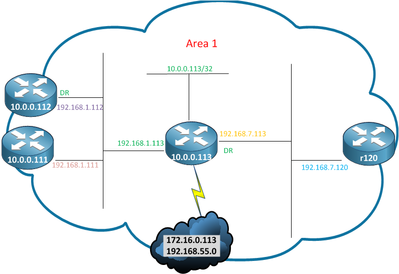
We know everything there is to know about Area 1. There is nothing to learn from router 10.0.0.113, since all of the links on that router are discovered. The next point to continue mapping the network would be on one of the ABRs. We will start with 10.0.0.112, or r112. Since r112 is an ABR it will have Type 1, 2, 3 and 4 information for both Area 1 and Area 0. We will want to focus on the Area 0 information. Let's get started by looking at our own Router LSA
OSPF Router with ID (10.0.0.112) (Process ID 1)
Router Link States (Area 0)
LS age: 720
Options: (No TOS-capability, DC)
LS Type: Router Links
Link State ID: 10.0.0.112
Advertising Router: 10.0.0.112
LS Seq Number: 80000262
Checksum: 0x20FD
Length: 36
Area Border Router
Number of Links: 1
Link connected to: a Transit Network
(Link ID) Designated Router address: 192.168.0.111
(Link Data) Router Interface address: 192.168.0.112
Number of MTID metrics: 0
TOS 0 Metrics: 10
Looks like we only have link 192.168.0.112 in this area, and we are not the DR on this segment. Now we take a look at the Type 2 LSA for this segment.
r112#show ip ospf data network 192.168.0.111
OSPF Router with ID (10.0.0.112) (Process ID 1)
Net Link States (Area 0)
Routing Bit Set on this LSA in topology Base with MTID 0
LS age: 388
Options: (No TOS-capability, DC)
LS Type: Network Links
Link State ID: 192.168.0.111 (address of Designated Router)
Advertising Router: 10.0.0.111
LS Seq Number: 80000261
Checksum: 0x759F
Length: 36
Network Mask: /24
Attached Router: 10.0.0.111
Attached Router: 10.0.0.110
Attached Router: 10.0.0.112
We see that the advertising router represents the Router ID of the DR, or 10.0.0.111, who we already know is the other ABR for Area 1. We also see that there is a third router on this segment with Router ID 10.0.0.110. Let's get the interface information from 10.0.0.111
r112#show ip ospf data router 10.0.0.111
OSPF Router with ID (10.0.0.112) (Process ID 1)
Router Link States (Area 0)
Routing Bit Set on this LSA in topology Base with MTID 0
LS age: 700
Options: (No TOS-capability, DC)
LS Type: Router Links
Link State ID: 10.0.0.111
Advertising Router: 10.0.0.111
LS Seq Number: 80000268
Checksum: 0x1605
Length: 36
Area Border Router
Number of Links: 1
Link connected to: a Transit Network
(Link ID) Designated Router address: 192.168.0.111
(Link Data) Router Interface address: 192.168.0.111
Number of MTID metrics: 0
TOS 0 Metrics: 10
One interface here, with IP 192.168.0.111. This is the same segment as r112 and Router 10.0.0.110. Finally, let's look at 10.0.0.110
r112#show ip ospf data router 10.0.0.110
OSPF Router with ID (10.0.0.112) (Process ID 1)
Router Link States (Area 0)
LS age: 1232
Options: (No TOS-capability, DC)
LS Type: Router Links
Link State ID: 10.0.0.110
Advertising Router: 10.0.0.110
LS Seq Number: 80000263
Checksum: 0x4E09
Length: 48
Number of Links: 2
Link connected to: a Transit Network
(Link ID) Designated Router address: 192.168.0.111
(Link Data) Router Interface address: 192.168.0.110
Number of MTID metrics: 0
TOS 0 Metrics: 10
Link connected to: a Transit Network
(Link ID) Designated Router address: 192.168.2.110
(Link Data) Router Interface address: 192.168.2.110
Number of MTID metrics: 0
TOS 0 Metrics: 10
We see that 10.0.0.110 owns the IP 192.168.0.110. We also see a second interface, 192.168.2.110. On this second segment 10.0.0.110 is the DR. Let's up the topology diagram for Area 0:
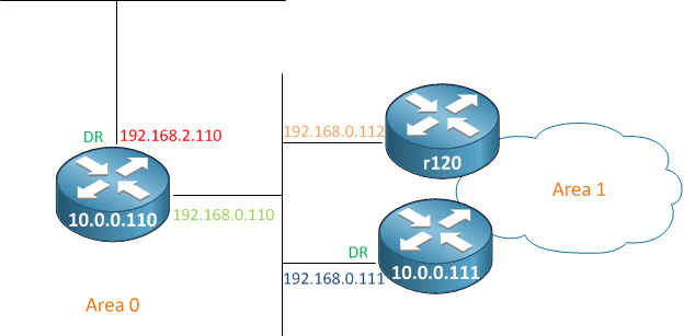
Let's keep moving down. First, we look at the Type 2 from 192.168.2.110, then we'll look at the Type 1 LSAs from the other routers on this segment.
r112#show ip ospf data net 192.168.2.110
OSPF Router with ID (10.0.0.112) (Process ID 1)
Net Link States (Area 0)
Routing Bit Set on this LSA in topology Base with MTID 0
LS age: 781
Options: (No TOS-capability, DC)
LS Type: Network Links
Link State ID: 192.168.2.110 (address of Designated Router)
Advertising Router: 10.0.0.110
LS Seq Number: 80000261
Checksum: 0x1779
Length: 32
Network Mask: /24
Attached Router: 10.0.0.110
Attached Router: 10.0.0.114
And now the Type 1 for 10.0.0.114
r112#show ip ospf data router 10.0.0.114
OSPF Router with ID (10.0.0.112) (Process ID 1)
Router Link States (Area 0)
Routing Bit Set on this LSA in topology Base with MTID 0
LS age: 889
Options: (No TOS-capability, DC)
LS Type: Router Links
Link State ID: 10.0.0.114
Advertising Router: 10.0.0.114
LS Seq Number: 80000265
Checksum: 0x1178
Length: 48
Area Border Router
AS Boundary Router
Number of Links: 2
Link connected to: a Stub Network
(Link ID) Network/subnet number: 192.168.3.0
(Link Data) Network Mask: 255.255.255.0
Number of MTID metrics: 0
TOS 0 Metrics: 10
Link connected to: a Transit Network
(Link ID) Designated Router address: 192.168.2.110
(Link Data) Router Interface address: 192.168.2.114
Number of MTID metrics: 0
TOS 0 Metrics: 10
We have two links again, one connected to the segment with 10.0.0.110 and a new segment. Again, notice that the segment 192.168.3.0 is a Stub Network, so there are no other OSPF speakers on this link. Now, before we think we've finished up, we haven't looked at the Type 3 LSAs that are generated by ABRs. We don't know if there is another ABR in Area 0, so let's look
Summary Net Link States (Area 0)
Link ID ADV Router Age Seq# Checksum
10.0.0.113 10.0.0.111 397 0x80000264 0x004394
10.0.0.113 10.0.0.112 17 0x80000264 0x003D99
10.0.0.119 10.0.0.114 1276 0x80000258 0x00715F
192.168.1.0 10.0.0.111 397 0x80000263 0x006F7B
192.168.1.0 10.0.0.112 792 0x80000262 0x006B7F
192.168.4.0 10.0.0.114 1036 0x80000261 0x0040A6
192.168.5.0 10.0.0.114 1036 0x80000261 0x0035B0
192.168.6.0 10.0.0.114 1036 0x80000260 0x00904B
192.168.7.0 10.0.0.111 397 0x80000265 0x008D4B
192.168.7.0 10.0.0.112 17 0x80000265 0x008750
Before addressing the new routes here, you can see the Type 3 LSAs in Area 0 that are generated by the two ABRs, 10.0.0.111 and 10.0.0.112. These routes here are all of the routes in Area 1, that we just described. This is how an ABR hides the details of an Area from the rest of the network.
We see four new networks all coming from the ABR 10.0.0.114. Now we can update our topology diagram of Area 0.
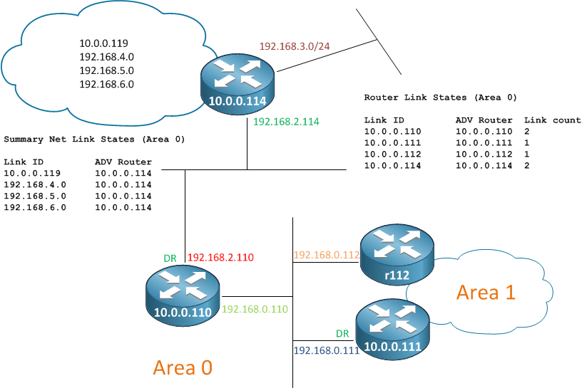
Again, we need to jump to our ABR to see what's going on in the rest of the network.
On r114 things get interesting. Looking at the LSAs we see that r114 is in 3 areas.
r114# show ip ospf data | i States
Router Link States (Area 0)
Net Link States (Area 0)
Summary Net Link States (Area 0)
Summary ASB Link States (Area 0)
Router Link States (Area 2)
Net Link States (Area 2)
Summary Net Link States (Area 2)
Router Link States (Area 3)
Net Link States (Area 3)
Summary Net Link States (Area 3)
Type-7 AS External Link States (Area 3)
Type-5 AS External Link States
But things look a little fishy in Area 2 and Area 3. Notice that Area 2 has no "Summary ASB Link States" (Type 4). Also notice that Area 3 has "Type-7 AS External Link States".
Let's start with Area 2.
If we are in an area that does not have any Type 4 LSAs, that area can not have external routes. OSPF works by linking the information carried in a Type-4 LSA to the information carried in the Type-5 LSA to build a tree. OSPF Stub areas do not allow any external information, matching this description. We can assume that Area 2 is a Stub Area.
Again, let's get a lay of the land by looking at the Router LSA summaries.
Router Link States (Area 2)
Link ID ADV Router Age Seq# Checksum Link count
10.0.0.114 10.0.0.114 23 0x8000026C 0x00B250 1
10.0.0.115 10.0.0.115 1584 0x80000269 0x00B350 1
10.0.0.116 10.0.0.116 745 0x8000026E 0x00F225 2
10.0.0.119 10.0.0.119 706 0x8000026B 0x0074E7 2
We can see there are four routers in the area. 10.0.0.116 and 10.0.0.119 both have two links.
Now let's look at our Router LSA
r114#show ip ospf data router 10.0.0.114
Router Link States (Area 2)
LS age: 1234
Options: (No TOS-capability, DC)
LS Type: Router Links
Link State ID: 10.0.0.114
Advertising Router: 10.0.0.114
LS Seq Number: 80000265
Checksum: 0xC049
Length: 36
Area Border Router
Number of Links: 1
Link connected to: a Transit Network
(Link ID) Designated Router address: 192.168.5.114
(Link Data) Router Interface address: 192.168.5.114
Number of MTID metrics: 0
TOS 0 Metrics: 10
Now the Type-2, Network LSA
r114#show ip ospf data net 192.168.5.114
OSPF Router with ID (10.0.0.114) (Process ID 1)
Net Link States (Area 2)
Routing Bit Set on this LSA in topology Base with MTID 0
LS age: 1312
Options: (No TOS-capability, DC)
LS Type: Network Links
Link State ID: 192.168.5.114 (address of Designated Router)
Advertising Router: 10.0.0.114
LS Seq Number: 80000263
Checksum: 0xD429
Length: 36
Network Mask: /24
Attached Router: 10.0.0.114
Attached Router: 10.0.0.115
Attached Router: 10.0.0.116
Next, the Router LSA (Type-1) of our Attached Routers
r114#show ip ospf data router 10.0.0.115
OSPF Router with ID (10.0.0.114) (Process ID 1)
Router Link States (Area 2)
LS age: 1000
Options: (No TOS-capability, DC)
LS Type: Router Links
Link State ID: 10.0.0.115
Advertising Router: 10.0.0.115
LS Seq Number: 80000263
Checksum: 0xBF4A
Length: 36
Number of Links: 1
Link connected to: a Transit Network
(Link ID) Designated Router address: 192.168.5.114
(Link Data) Router Interface address: 192.168.5.115
Number of MTID metrics: 0
TOS 0 Metrics: 10
r114#show ip ospf data router 10.0.0.116
OSPF Router with ID (10.0.0.114) (Process ID 1)
Router Link States (Area 2)
LS age: 269
Options: (No TOS-capability, DC)
LS Type: Router Links
Link State ID: 10.0.0.116
Advertising Router: 10.0.0.116
LS Seq Number: 80000268
Checksum: 0xFE1F
Length: 48
Number of Links: 2
Link connected to: a Transit Network
(Link ID) Designated Router address: 192.168.5.114
(Link Data) Router Interface address: 192.168.5.116
Number of MTID metrics: 0
TOS 0 Metrics: 10
Link connected to: a Transit Network
(Link ID) Designated Router address: 192.168.6.119
(Link Data) Router Interface address: 192.168.6.116
Number of MTID metrics: 0
TOS 0 Metrics: 10
Let's digest this here. First 10.0.0.115 has a single interface with IP 192.168.5.115. Next we see 10.0.0.116 with two interfaces, 192.168.5.116 and 192.168.6.116. Let's update the topology and then take a look at the segment with DR 192.168.6.119. This must be the router 10.0.0.119, the only router in Area 2 we haven't looked at yet.
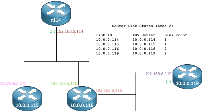
Remember that routers 10.0.0.116 and 10.0.0.119 both had two links. We have discovered the two links on 10.0.0.116, but we still have one link on 10.0.0.119 to find, so let's look at the Type-1 for 10.0.0.119
r114#show ip ospf data router 10.0.0.119
OSPF Router with ID (10.0.0.114) (Process ID 1)
Router Link States (Area 2)
LS age: 1272
Options: (No TOS-capability, DC)
LS Type: Router Links
Link State ID: 10.0.0.119
Advertising Router: 10.0.0.119
LS Seq Number: 8000026B
Checksum: 0x74E7
Length: 48
Number of Links: 2
Link connected to: a Stub Network
(Link ID) Network/subnet number: 10.0.0.119
(Link Data) Network Mask: 255.255.255.255
Number of MTID metrics: 0
TOS 0 Metrics: 1
Link connected to: a Transit Network
(Link ID) Designated Router address: 192.168.6.119
(Link Data) Router Interface address: 192.168.6.119
Number of MTID metrics: 0
TOS 0 Metrics: 10
Now we have discovered all of the links in Area 2. Because Area 2 still receives Type-3 LSAs, it will know about all of the links in the OSPF network. The only thing it will not have will be the external routes that are injected into OSPF.

Remember that r114 was in three Areas: Area 0, Areas 2 and Area 3. Before digging into Area 3, let's take another look at the LSAs that exist in Area 3.
r114#show ip ospf data | i Area 3
Router Link States (Area 3)
Net Link States (Area 3)
Summary Net Link States (Area 3)
Type-7 AS External Link States (Area 3)
We see Type 1 (Router Link States), Type 2 (Net Link State), Type 3 (Summary Net Link) and Type 7 (Type-7 AS External). Similar to Area 2, we do not see Type 4 or Type 5 LSAs. However we see Type-7 LSAs, which only exist in Not So Stubby Areas (NSSA). In a normal Stub area external route information is not allowed. NSSA areas allow us to have all of the features of a Stub area (no externals from other parts of the network) while still allowing external information to be originated in this area. To accomplish this, NSSA areas do not allow Type-5 (normal external LSAs) and use a special Type-7 LSAs. When the Type-7 arrives on the ABR (r114 in this case), the ABR must convert this Type-7 to a Type-5 for the rest of the network. We'll take a look at this process in a little while.
First, let's see how many routers and links are in Area 3
Router Link States (Area 3)
Link ID ADV Router Age Seq# Checksum Link count
10.0.0.114 10.0.0.114 1610 0x80000335 0x00B37A 1
10.0.0.117 10.0.0.117 1344 0x80000333 0x00A881 1
10.0.0.118 10.0.0.118 802 0x80000332 0x00AE77 1
We have 3 routers, each with 1 link. Now, as always, take a look at our Type-1
r114#show ip ospf data router 10.0.0.114
Router Link States (Area 3)
LS age: 723
Options: (No TOS-capability, DC)
LS Type: Router Links
Link State ID: 10.0.0.114
Advertising Router: 10.0.0.114
LS Seq Number: 80000334
Checksum: 0xB579
Length: 36
Area Border Router
AS Boundary Router
Number of Links: 1
Link connected to: a Transit Network
(Link ID) Designated Router address: 192.168.4.117
(Link Data) Router Interface address: 192.168.4.114
Number of MTID metrics: 0
TOS 0 Metrics: 10
A single link with IP 192.168.4.114 and DR 192.168.4.117. Now the Type-2
r114#show ip ospf data net 192.168.4.117
OSPF Router with ID (10.0.0.114) (Process ID 1)
Net Link States (Area 3)
Routing Bit Set on this LSA in topology Base with MTID 0
LS age: 635
Options: (No TOS-capability, DC)
LS Type: Network Links
Link State ID: 192.168.4.117 (address of Designated Router)
Advertising Router: 10.0.0.117
LS Seq Number: 80000330
Checksum: 0xCE50
Length: 36
Network Mask: /24
Attached Router: 10.0.0.117
Attached Router: 10.0.0.114
Attached Router: 10.0.0.118
Here are three routers attached to this segment. r114, the DR and a third router. Now the Type-1 LSAs for the other routers.
r114#show ip ospf data router 10.0.0.117
OSPF Router with ID (10.0.0.114) (Process ID 1)
Router Link States (Area 3)
LS age: 794
Options: (No TOS-capability, DC)
LS Type: Router Links
Link State ID: 10.0.0.117
Advertising Router: 10.0.0.117
LS Seq Number: 80000333
Checksum: 0xA881
Length: 36
Number of Links: 1
Link connected to: a Transit Network
(Link ID) Designated Router address: 192.168.4.117
(Link Data) Router Interface address: 192.168.4.117
Number of MTID metrics: 0
TOS 0 Metrics: 10
r114#show ip ospf data router 10.0.0.118
OSPF Router with ID (10.0.0.114) (Process ID 1)
Router Link States (Area 3)
Routing Bit Set on this LSA in topology Base with MTID 0
LS age: 257
Options: (No TOS-capability, DC)
LS Type: Router Links
Link State ID: 10.0.0.118
Advertising Router: 10.0.0.118
LS Seq Number: 80000332
Checksum: 0xAE77
Length: 36
AS Boundary Router
Number of Links: 1
Link connected to: a Transit Network
(Link ID) Designated Router address: 192.168.4.117
(Link Data) Router Interface address: 192.168.4.118
Number of MTID metrics: 0
TOS 0 Metrics: 10
We see IPs 192.168.4.118 and 192.168.4.117. Here's the topology for Area 3.
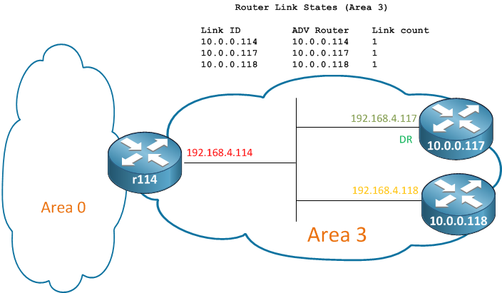
But let's not forget about the Type-7 LSAs we saw earlier. Because these are Type-7, we are not looking at external LSAs but nssa-external LSAs
r114#show ip ospf data nssa-external
OSPF Router with ID (10.0.0.114) (Process ID 1)
Type-7 AS External Link States (Area 3)
Routing Bit Set on this LSA in topology Base with MTID 0
LS age: 952
Options: (No TOS-capability, Type 7/5 translation, DC)
LS Type: AS External Link
Link State ID: 172.16.0.118 (External Network Number )
Advertising Router: 10.0.0.118
LS Seq Number: 800000FF
Checksum: 0xEC13
Length: 36
Network Mask: /32
Metric Type: 2 (Larger than any link state path)
MTID: 0
Metric: 20
Forward Address: 192.168.4.118
External Route Tag: 0
This is the LSA representing the external network 172.16.0.118/32. Within this area the routers should send traffic for this destination to the Forwarding Address of 192.168.4.118. Once the LSA arrives on the ABR, r114, it will be converted into a Type-5 LSA and sent to all other areas (that aren't stubs, meaning that Area 2 will not see this LSA). We can confirm this by looking at the Type-5 LSAs
r114#show ip ospf data external 172.16.0.118
OSPF Router with ID (10.0.0.114) (Process ID 1)
Type-5 AS External Link States
LS age: 146
Options: (No TOS-capability, DC)
LS Type: AS External Link
Link State ID: 172.16.0.118 (External Network Number )
Advertising Router: 10.0.0.114
LS Seq Number: 80000101
Checksum: 0x9477
Length: 36
Network Mask: /32
Metric Type: 2 (Larger than any link state path)
MTID: 0
Metric: 20
Forward Address: 192.168.4.118
External Route Tag: 0
Here we see the Type-5 originated not by 10.0.0.118, like the Type-7, but by 10.0.0.114. This is due to the Type-7 to Type-5 conversion. Since r114 is generating a new LSA it sets itself as the Advertising Router. You'll also notice that the Forwarding Address has remained the same. When other routers in the network build the tree to reach this external destination they will build to the best ABR to reach this network (since it would be part of a Type-3 LSA). For more information on Forwarding Addresses, there is a great doc on Cisco.com.
With all of this information we can finish the topology for Area 3
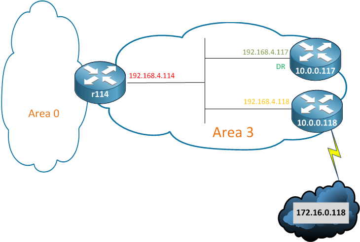
and then for the entire OSPF network.
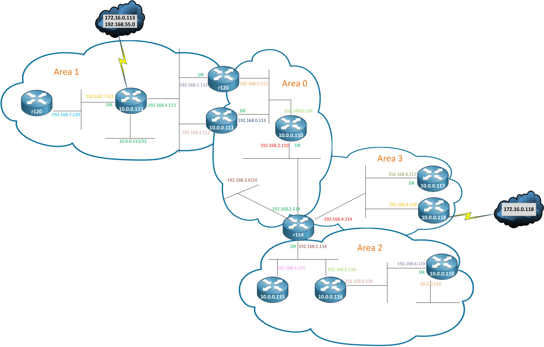
Summary
Hopefully reading the OSPF topology is a little more clear now. The less obvious takeaways are how OSPF scales by hiding topology information. You noticed that in an area we have a large number of Type 1 and Type 2 LSAs. Outside of that area there is only a single Type-3 LSA generated by each ABR. We can also use Stub Areas to hide external information, keeping even less information in the LSDB of the routers in those areas.
Finally, think about how each LSA type links together. OSPF's SPF algorithm links different pieces of information together. For a router in Area 1 to reach the external route in Area 3, it has to look at the Type-5 that represents the external route. Then it has to look at the Type-4 representing the ABR on the area that the ASBR lives in. Then we have to look at the Type-3 to get to that remote ABR. Finally we look at the Type-1 and Type-2 LSAs in our area to determine how to get to our closest ABR.
Each LSA serves a specific purpose and they all fit together to supply end-to-end connectivity.
- Mark as Read
- Mark as New
- Bookmark
- Permalink
- Report Inappropriate Content
Awesome!!!!
On how to make sense of the radom chatoic ospf database and build the network topology just by intrepretting the sh ip odpf db command.
LSAs in live action here!!
- Mark as Read
- Mark as New
- Bookmark
- Permalink
- Report Inappropriate Content
Outstanding!! Simply the best discussion on this subject I have seen.
- Mark as Read
- Mark as New
- Bookmark
- Permalink
- Report Inappropriate Content
Excellent document.
- Mark as Read
- Mark as New
- Bookmark
- Permalink
- Report Inappropriate Content
Simply Awesome..!!
Prior reading this doc I used to get confused while reading ospf database to build topologies but this doc clears all my doubts and now I can build topologies very easily without any doubts..
- Mark as Read
- Mark as New
- Bookmark
- Permalink
- Report Inappropriate Content
This document really brought a lot of the pieces together for OSPF. I've studied the LSAs and know how to spout off canned answers about what an LSA means, but this document actually gave me knowledge on interpreting the LSAs and building the trees.
- Mark as Read
- Mark as New
- Bookmark
- Permalink
- Report Inappropriate Content
Too Good !!! Cleared so many of the concepts...
Thanks for the post...
- Mark as Read
- Mark as New
- Bookmark
- Permalink
- Report Inappropriate Content
Very Good!
Only one doubt about the this last sentence at the paper , " Then we have to look at the Type-3 to get to that remote ABR. "
I remember that the Type-3 LSA's ABR means the local ABR.
- Mark as Read
- Mark as New
- Bookmark
- Permalink
- Report Inappropriate Content
very useful
- Mark as Read
- Mark as New
- Bookmark
- Permalink
- Report Inappropriate Content
Just awesome!!!!!!!!!!!!!
- Mark as Read
- Mark as New
- Bookmark
- Permalink
- Report Inappropriate Content
thank you it did help me get thru my lab.....GREAT
- Mark as Read
- Mark as New
- Bookmark
- Permalink
- Report Inappropriate Content
I agree with the poster with this statement. Type 3 LSAs is what allows one router to obtain "O IA" routes. Type 3 LSA's allow a remote ABR to tell about the networks in one area and bring them into another area.
- Mark as Read
- Mark as New
- Bookmark
- Permalink
- Report Inappropriate Content
awesome post. Now OSPF is clear !!
- Mark as Read
- Mark as New
- Bookmark
- Permalink
- Report Inappropriate Content
Excellent post. Highly recommended if you were like me fearful of the output of ip ospf database command
- Mark as Read
- Mark as New
- Bookmark
- Permalink
- Report Inappropriate Content
Thank you for this great post. One question -
"Type 4, Summary Network LSAs are next"
Did you mean ASBR Summary LSA? Although it in fact is network summary LSA, calling Type4 LSA a Summary Network LSA (without referencing ASBR) may bring some confusion.
- Mark as Read
- Mark as New
- Bookmark
- Permalink
- Report Inappropriate Content
OSPF State is FULL
Really Amazing Explanation!..
Find answers to your questions by entering keywords or phrases in the Search bar above. New here? Use these resources to familiarize yourself with the community:
