- Cisco Community
- Technology and Support
- Networking
- Networking Knowledge Base
- Static Routes With Next Hop As An Exit Interface Or An IP Address
- Subscribe to RSS Feed
- Mark as New
- Mark as Read
- Bookmark
- Subscribe
- Printer Friendly Page
- Report Inappropriate Content
- Subscribe to RSS Feed
- Mark as New
- Mark as Read
- Bookmark
- Subscribe
- Printer Friendly Page
- Report Inappropriate Content
11-03-2012 02:04 PM - edited 03-01-2019 04:52 PM
Introduction:
This document describes the difference between implementation of static routes with next hop as an exit interface or an IP address.
!-- Pointing to next hop address
ip route 0.0.0.0 0.0.0.0 10.1.1.2
!-- Pointing to the interface
ip route 0.0.0.0 0.0.0.0 fa0/0
Basic Overview:
For forwarding packet to the destination, the router must determine the exit interface and rewrite the L2 frame before putting the packet on the wire. In order for a router to write the L2 frame it must resolve the IP address to its corresponding L2 address and reconstruct the frame before sending to the next hop. The function of address resolution can be done dynamically using protocols like ARP in Ethernet or Statically/Dynamically learned DLCI in frame-relay.
There are two points need to be understand, when you configure static route on router.
1) If you configured static route pointed to next hop IP address, for every destination forwarding router requires only L2 address of next hop IP address to rewrite the L2 frame.
Example: ip route 2.2.2.0 255.255.255.0 10.1.1.2
For routing packet to destination address 2.2.2.2, router requires L2 mac address of 10.1.1.2.
2) If you configured static route point to outgoing interface, forwarding router assume destination address is directly connected to that interface and router will try to find the L2 address of the destination by sending ARP request out of the interface to the destination address in case of Ethernet or looking for a static/dynamic map entry in the mapping table in case of frame-relay.
Example: ip route 2.2.2.0 255.255.255.0 fa0/0
For routing packet to the destination address 2.2.2.2, router assumes host 2.2.2.2 is directly connected to the interface fa0/0 and it requires L2 mac address for 2.2.2.2.
In general, interfaces can be point to point or multi-point. The above mentioned conditions work differently in scenarios of Point to point and multipoint interface.
In point to point interface, by definition two devices are directly connected, so in case if you configure static route pointing to outgoing interface or next hop IP address does not make a difference, router uses L2 address of next hop IP address of interface for routing packet to every destination address.
In multipoint interface, by definition interface can have multiple devices connected to it. So as mention above in point number two, if you configure static route point to next-hop, router need L3 to L2 resolution for each destination prefixes. Ethernet is an example of multi-point interfaces whereas Frame-relay and ATM can be multi-point interface or point to point depending on the configuration.
Configuration overview:
The topology and initial configurations are shown below:
Topology diagram:
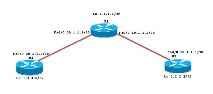
Initial configuration:
R1R2R3
| interface Loopback0 ip address 1.1.1.1 255.255.255.255 ! interface FastEthernet0/0 ip address 10.1.1.2 255.255.255.252 duplex auto speed auto ! interface FastEthernet0/1 ip address 20.1.1.1 255.255.255.0 duplex auto speed auto ! ip route 2.2.2.2 255.255.255.255 10.1.1.1 ip route 3.3.3.3 255.255.255.255 20.1.1.2 | interface Loopback0 ip address 2.2.2.2 255.255.255.255 ! interface FastEthernet0/0 ip address 10.1.1.1 255.255.255.252 duplex auto speed auto ! ip route 0.0.0.0 0.0.0.0 10.1.1.2 | interface Loopback0 ip address 3.3.3.3 255.255.255.255 ! interface FastEthernet0/0 ip address 20.1.1.2 255.255.255.252 duplex auto speed auto ! ip route 0.0.0.0 0.0.0.0 20.1.1.1 |
Case1: Configured static route on R2 point to the next hop address of neighboring router R1. As discussed above, for forwarding every packet to destination prefix R2 will use destination mac address of R1 in L2 frame.
Verifying connectivity from R2 to R1 and R3 loopback addresses:
R2#ping 1.1.1.1 so 2.2.2.2
Type escape sequence to abort.
Sending 5, 100-byte ICMP Echos to 1.1.1.1, timeout is 2 seconds:
Packet sent with a source address of 2.2.2.2
!!!!!
Success rate is 100 percent (5/5), round-trip min/avg/max = 20/28/40 ms
R2#ping 3.3.3.3 so 2.2.2.2
Type escape sequence to abort.
Sending 5, 100-byte ICMP Echos to 3.3.3.3, timeout is 2 seconds:
Packet sent with a source address of 2.2.2.2
!!!!!
Success rate is 100 percent (5/5), round-trip min/avg/max = 16/35/60 ms
R2#sh ip arp
Protocol Address Age (min) Hardware Addr Type Interface
Internet 10.1.1.1 - c000.3148.0000 ARPA FastEthernet0/0
Internet 10.1.1.2 0 c001.3148.0000 ARPA FastEthernet0/0
Case2: Configured a static route on R2 point to the outgoing interface. As discussed above, for forwarding every packet R2 assume destination address is directly connected to that interface and will try to find the L2 mac address of the every destination by sending ARP request out of the interface to the destination address.
R2(config)#no ip route 0.0.0.0 0.0.0.0 10.1.1.2
R2(config)#ip route 0.0.0.0 0.0.0.0 fa0/0
Connectivity verification from R2 to R1 and R3 loopback addresses. Also IP packet debug turned on R2 to get closer packet level view.
R2#debug ip packet detail
IP packet debugging is on (detailed)
R2#ping 3.3.3.3 so 2.2.2.2
Type escape sequence to abort.
Sending 5, 100-byte ICMP Echos to 3.3.3.3, timeout is 2 seconds:
Packet sent with a source address of 2.2.2.2
IP: tableid=0, s=2.2.2.2 (local), d=3.3.3.3 (FastEthernet0/0), routed via RIB
IP: s=2.2.2.2 (local), d=3.3.3.3 (FastEthernet0/0), len 100, sending
ICMP type=8, code=0
IP: s=2.2.2.2 (local), d=3.3.3.3 (FastEthernet0/0), len 100, encapsulation failed
ICMP type=8, code=0.
IP: tableid=0, s=2.2.2.2 (local), d=3.3.3.3 (FastEthernet0/0), routed via RIB
IP: s=2.2.2.2 (local), d=3.3.3.3 (FastEthernet0/0), len 100, sending
ICMP type=8, code=0
IP: s=2.2.2.2 (local), d=3.3.3.3 (FastEthernet0/0), len 100, encapsulation failed
R2#sh ip arp
Protocol Address Age (min) Hardware Addr Type Interface
Internet 1.1.1.1 0 Incomplete ARPA
Internet 3.3.3.3 0 Incomplete ARPA
Internet 10.1.1.1 - c000.3148.0000 ARPA FastEthernet0/0
Internet 10.1.1.2 16 c001.3148.0000 ARPA FastEthernet0/0
Internet 10.1.1.5 - c000.3148.0001 ARPA FastEthernet0/1
As 1.1.1.1 and 3.3.3.3 prefixes are not directly connected to fa0/0, R2 is not getting L2 mac address of these prefixes hence ARP table entry is showing incomplete and there is L2 encapsulation failure on R2 is dropping packets for this destination.
There are two tricky works around are available but these are not solutions just explained for user’s information.
1) Enabling proxy ARP on next hop router:
If you enable proxy ARP on router, Whenever router get address resolution request it send the proxy ARP of its own interface address to the requested router, Only if the prefixes are present in its routing table.
In this example R1 sends proxy ARP i.e. L2 mac address of 10.1.1.2 to R2 for prefixes 3.3.3.3 and 2.2.2.2, as both are in its routing table. By default proxy ARP is enable on the most of the routers.
R1#conf t
Enter configuration commands, one per line. End with CNTL/Z.
R1(config)#int fa0/0
R1(config-if)#ip proxy-arp
R1(config-if)#do sh ip int fa0/0 | in Proxy
Proxy ARP is enabled
Local Proxy ARP is enabled
Verifying connectivity from R2 to R1 and R3 loopback address:
R2#ping 1.1.1.1 so 2.2.2.2
Type escape sequence to abort.
Sending 5, 100-byte ICMP Echos to 1.1.1.1, timeout is 2 seconds:
Packet sent with a source address of 2.2.2.2
!!!!!
Success rate is 100 percent (5/5), round-trip min/avg/max = 20/28/40 ms
R2#ping 3.3.3.3 so 2.2.2.2
Type escape sequence to abort.
Sending 5, 100-byte ICMP Echos to 3.3.3.3, timeout is 2 seconds:
Packet sent with a source address of 2.2.2.2
!!!!!
Success rate is 100 percent (5/5), round-trip min/avg/max = 16/35/60 ms
Take closer look at Arp table of R2, it is showing that same mac address present for 3.3.3.3 and 1.1.1.1 prefixes in address resolution table because R1 is sending proxy ARP of its own interface address.
R2#sh ip arp
Protocol Address Age (min) Hardware Addr Type Interface
Internet 1.1.1.1 0 c001.3148.0000 ARPA FastEthernet0/0
Internet 3.3.3.3 0 c001.3148.0000 ARPA FastEthernet0/0
Internet 10.1.1.1 - c000.3148.0000 ARPA FastEthernet0/0
Internet 10.1.1.2 40 c001.3148.0000 ARPA FastEthernet0/0
Hence this could result in a large amount of broadcast traffic and a large no of ARP cache on R2, especially if the static route was a default route used for internet traffic.
2) Adding manual ARP entries in ARP table:
You can also add manual ARP entries for destination prefixes to build L2 frame as shown below:
R2(config)#arp 1.1.1.1 c001.3148.0000 arpa
R2(config)#arp 3.3.3.3 c001.3148.0000 arpa
R2#sh ip arp
Protocol Address Age (min) Hardware Addr Type Interface
Internet 1.1.1.1 - c001.3148.0000 ARPA
Internet 3.3.3.3 - c001.3148.0000 ARPA
Internet 10.1.1.1 - c000.3148.0000 ARPA FastEthernet0/0
Internet 10.1.1.2 4 c001.3148.0000 ARPA FastEthernet0/0
To build L2 frame for each destination prefixes you will need to add manual entries in address resolution table.
Conclusion:
->For point to point interfaces, you can use static routes that point to the interface or to the next hop address. There is only one possible next hop and its L2 address will be used to build L2 frame.
->For multipoint/Broadcast interfaces, it is more suitable to use static routes that point to a next hop address to avoid the need for resolving every destination address to its L2 address. As you have seen above it is still possible to use static routes pointing to the interface but not a scalable solution.
Base Initial configuration:
- Mark as Read
- Mark as New
- Bookmark
- Permalink
- Report Inappropriate Content
Good post !!!
Thx
But for : 1) Enabling proxy ARP on next hop router:
will not work because you will receive a message from debug arp like "Worng Cable"..
- Mark as Read
- Mark as New
- Bookmark
- Permalink
- Report Inappropriate Content
Hello Dan,
Thanks for your positive feedback
I tried Method 1 on Lab devices it was working fine for me. Generally enabling proxy arp is not best solution to above issue. Proxy ARP is the name given when a node responds to an arp request on behalf of another node. This is commonly used to redirect traffic sent to one IP address to another device, therefore improper use of Proxy ARP allows security vulnerability.
Regards,
Ashish Shirkar
(Technical Community Manager-Network Infrastructure)
- Mark as Read
- Mark as New
- Bookmark
- Permalink
- Report Inappropriate Content
Thanks a lot Ashish Shirkar for your great explanation of this topic!
Now I understand what's the difference in defining an IP or an interface in 'ip route' statements.
Tomorrow I have my CCNA exam - in case there is a question on this, I'm sure I will give the correct answer
- Mark as Read
- Mark as New
- Bookmark
- Permalink
- Report Inappropriate Content
Hello Marcel,
Thanks for your positive feedback, really appreciate. Best of luck for your Exam
Regards,
Ashish Shirkar
(TCM-NI)
- Mark as Read
- Mark as New
- Bookmark
- Permalink
- Report Inappropriate Content
- Mark as Read
- Mark as New
- Bookmark
- Permalink
- Report Inappropriate Content
proxy arp is enabled on all the interfaces by default anyways so not sure what you meant by "not a scalable solution"
- Mark as Read
- Mark as New
- Bookmark
- Permalink
- Report Inappropriate Content
i hv joined r1 and r2 with f0/0 and f0/1.i gave next hop on f0/0 and exit interface on f0/1.i am using 10 network 0n f0/0 and 20 on f0/1.although i hb enabled proxy arp and local proxy arp,my pings are droping alternatively.please explain this.
- Mark as Read
- Mark as New
- Bookmark
- Permalink
- Report Inappropriate Content
I am not the author of the article and so can not be sure what he meant. But I can certainly explain why I agree that a static route specifying only the outbound interface (when it is an Ethernet type of interface) is not a scalable solution.
Let us start by reviewing what is the case when the static route specifies the next hop address (perhaps the next hop address is 10.1.1.2). In this situation the router/switch arp table will have a single entry for 10.1.1.2 and that entry will be used for every packet that is forwarded using this static route. So the router/switch could forward packets for 10,000 different remote addresses but will require only the single entry in the arp table.
Then let us review what is the case then the static route specifies the outbound interface (perhaps it is fa0/0). Now the router/switch will need to do an arp request for each remote address for which it is forwarding traffic. If it is forwarding traffic to 10,000 different remote addresses then it will generate 10,000 entries in the arp table. So let us consider the impact of having 10,000 entries in the arp table instead on a single entry in the arp table. First impact is the increase in memory required to store these 10,000 entries. Second impact is that an arp entry times out in 4 hours and must be refreshed. So a static route specifying the output interface will cause 10,000 arp refreshes every 4 hours rather than the single arp refresh required if the static route specified the next hop.
HTH
Rick
- Mark as Read
- Mark as New
- Bookmark
- Permalink
- Report Inappropriate Content
Hi Rick,
Is the best way to configure a static route to a subnet would be using both the exit interface and the next-hop IP address? What if you configured HSRP on the next-hop? Do you then use the HSRP IP as the next-hop IP or use the Physical IP?
Example:
Next-hop device
interface Vlan5
description User Transit_vlan
ip address 172.16.87.197 255.255.255.248
standby 5 ip 172.16.87.196
standby 5 timers 5 15
standby 5 priority 115
standby 5 preempt
On my router going to vlan 10 or 20...
ip route 172.16.87.0 255.255.255.0 GigabitEthernet0/0/0.5 172.16.87.196
#OR
ip route 172.16.87.0 255.255.255.0 GigabitEthernet0/0/0.5 172.16.87.197
Which is better?
Cheers,
Cheers,
- Mark as Read
- Mark as New
- Bookmark
- Permalink
- Report Inappropriate Content
Blue Phonix.
For sure HSRP! Is the reason why you are using HSRP. If you put the physical IP and it failed - then you lost the next hop.
BRG.
M.S.
- Mark as Read
- Mark as New
- Bookmark
- Permalink
- Report Inappropriate Content
I find several aspects of your question puzzling: your static route is for network 172.16.87.0 with a /24 mask. But the interface configuration shows 172.16.87.192 with a /29 mask. Is this inconsistency on purpose?
Also confusing is that fact that your static route seems to say that if we go out Gig0/0/0.5 we will find 172.16.87.196 and 172.16.87.197 as connected addresses. So how does the device on which you configure this static route relate to the HSRP configuration? Is it a participant in HSRP or is it a third router/switch in this network?
Clarification of these points might change my answer a bit, but in general I would suggest that the static route using the HSRP address is preferable to the route using the physical interface address. My logic in this is that using the HSRP address provides some redundancy while using the physical interface address works only if that router is up but would fail if that router was down and its HSRP peer was still active.
HTH
Rick
- Mark as Read
- Mark as New
- Bookmark
- Permalink
- Report Inappropriate Content
Oh Sorry!
the network is 172.16.84.0/24
- Mark as Read
- Mark as New
- Bookmark
- Permalink
- Report Inappropriate Content
That does resolve one of the puzzling things in your example. It still leaves some confusion about the relationship of the device where this static route is configured and the devices that are running HSRP. Also a bit confusing is the reference in your example about the router going to vlan 10 and 20 when there is no information about those vlans.
But I believe that for most circumstances my response is still valid that it would be preferable to have the next hop in the static route be the HSRP shared address rather than using the physical interface address.
HTH
Rick
- Mark as Read
- Mark as New
- Bookmark
- Permalink
- Report Inappropriate Content
I believe I use HSRP so the LAN can have redundancy from the switch side... My static is from the WAN side going back to the LAN.
Find answers to your questions by entering keywords or phrases in the Search bar above. New here? Use these resources to familiarize yourself with the community: