- Cisco Community
- Technology and Support
- Networking
- Networking Knowledge Base
- Understanding SPAN,RSPAN,and ERSPAN
- Subscribe to RSS Feed
- Mark as New
- Mark as Read
- Bookmark
- Subscribe
- Printer Friendly Page
- Report Inappropriate Content
- Subscribe to RSS Feed
- Mark as New
- Mark as Read
- Bookmark
- Subscribe
- Printer Friendly Page
- Report Inappropriate Content
05-03-2013 12:21 PM - edited 03-01-2019 04:55 PM
Introduction:
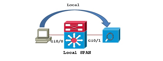
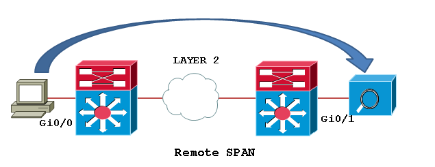
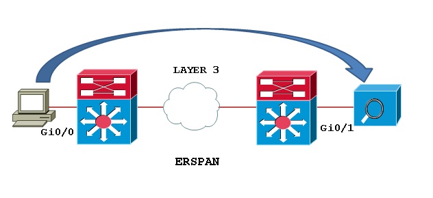
Switch port Analyzer (SPAN) is an efficient, high performance traffic monitoring system. It duplicated network traffic to one or more monitor interfaces as it transverse the switch. SPAN is used for troubleshooting connectivity issues and calculating network utilization and performance, among many others. There are three types of SPANs supported on Cisco products, which are illustrated in below diagram.
Types of SPAN:


Local SPAN: Mirrors traffic from one or more interface on the switch to one or more interfaces on the same switch.
Remote SPAN (RSPAN): An extension of SPAN called remote SPAN or RSPAN. RSPAN allows you to monitor traffic from source ports distributed over multiple switches, which means that you can centralize your network capture devices. RSPAN works by mirroring the traffic from the source ports of an RSPAN session onto a VLAN that is dedicated for the RSPAN session. This VLAN is then trunked to other switches, allowing the RSPAN session traffic to be transported across multiple switches. On the switch that contains the destination port for the session, traffic from the RSPAN session VLAN is simply mirrored out the destination port.
Encapsulated remote SPAN (ERSPAN): encapsulated Remote SPAN (ERSPAN), as the name says, brings generic routing encapsulation (GRE) for all captured traffic and allows it to be extended across Layer 3 domains.
ERSPAN is a Cisco proprietary feature and is available only to Catalyst 6500, 7600, Nexus, and ASR 1000 platforms to date. The ASR 1000 supports ERSPAN source (monitoring) only on Fast Ethernet, Gigabit Ethernet, and port-channel interfaces.
Configuration Example:
Configuring Local SPAN: Local SPAN configures using “monitor session” command specifying source and destination on the same switch.
Switch1# configure terminal
Switch1(config)# monitor session 1 source interface fastEthernet0/2
Switch1(config)# monitor session 1 destination interface fastEthernet0/24
Switch1(config)#end
Local SPAN configuration syntax on Cisco IOS release 12.2(33)SXH and beyond as shown below.
monitor session 1 type local
source int fa0/2
destination int fa0/24
Configuring RSPAN:
Step1: In order to configure RSPAN you need to have an RSPAN VLAN, those VLANs have special properties and can’t be assigned to any access ports. To create a VLAN for RSPAN on Cisco IOS, you must create the VLAN via the config-vlan configuration mode, as opposed to using the older VLAN database configuration mode. During the process of defining VLAN parameters, you must specify that the new VLAN is an RSPAN VLAN by configuring the remote-span VLAN configuration command.
Switch1# configure terminal
Switch1(config)# vlan 200
Switch1(config-vlan)# remote-span
Switch1(config-vlan)# end
Switch1# show vlan remote-span
Remote SPAN VLANs
------------------------------------------------------------------------------
200
Switch2# configure terminal
Switch2(config)# vlan 200
Switch2(config-vlan)# remote-span
Switch2(config-vlan)# end
Switch2# show vlan remote-span
Remote SPAN VLANs
------------------------------------------------------------------------------
200
Step2: Then configure the RSPAN on Source switch: Unlike SPAN, where the source and destination ports exist on the same switch, the source and destination ports for an RSPAN session reside on different switches. This requires a separate RSPAN source session to be configured, as well as a separate RSPAN destination session to be configured.
Switch1# configure terminal
Switch1(config)# monitor session 1 source interface fastEthernet0/2 rx
Switch1(config)# monitor session 1 destination remote vlan 200
reflector-port fastEthernet0/24
Switch1(config)# exit
Switch1# show monitor
Session 1
---------
Type : Remote Source Session
Source Ports :
Rx : Fa0/2
Reflector Port : Fa0/24
Dest RSPAN VLAN : 200
Step3: Configure the RSPAN on destination switch:
Switch2# configure terminal
Switch2(config)# monitor session 1 source remote vlan 200
Switch2(config)# monitor session 1 destination interface fastEthernet0/3
Switch2(config)# exit
The RSPAN VLAN should be allowed in ALL trunks between the involved switches (Source and Destination switches in this case); if you have enabled "pruning" in your network, remove the RSPAN VLAN from the pruning, with the command: “switchport trunk pruning vlan remove <RSPAN VLAN ID>” under the interface configure as trunk.
Configuring ERSPAN:
In this example we will capture received traffic on the ASR 1002 (GigabitEthernet0/1/0) and send to Catalyst 6509 Gig2/2/1. This traffic will simply be captured, encapsulated in GRE by ASR 1002 natively by the QFP chipset and routed over to the Catalyst 6509. A sniffing station on the 6500 attached to GE2/2/1 will see the complete Ethernet frame (L2 to L7) information.
Configuring source interface, direction of traffic, and ERSPAN session ID on the ASR 1002.
ASR1002(config)# monitor session 1 type erspan-source
ASR1002(config-mon-erspan-src)# source interface gig0/1/0 rx
ASR1002(config-mon-erspan-src)# no shutdown
ASR1002(config-mon-erspan-src)# destination
ASR1002(config-mon-erspan-src-dst)# erspan-id 101
ASR1002(config-mon-erspan-src-dst)# ip address 10.1.1.1
ASR1002(config-mon-erspan-src-dst)# origin ip address 172.16.1.1
Configuring Catalyst 6509 to receive traffic from the source session on the ASR 1002
SW6509(config)# monitor session 2 type erspan-destination
SW6509(config-mon-erspan-dst)# destination interface gigabitEthernet2/2/1
SW6509(config-mon-erspan-dst)# no shutdown
SW6509(config-mon-erspan-dst)# source
SW6509(config-mon-erspan-dst-src)# erspan-id 101
SW6509(config-mon-erspan-dst-src)# ip address 10.1.1.1
You can use the show monitor session command to verify the configuration:
ASR1002#sh monitor session 1
Session 1
---------
Type : ERSPAN Source Session
Status : Admin Enabled
Source Ports :
RX Only : Gi0/1/0
Destination IP Address : 10.1.1.1
MTU : 1464
Destination ERSPAN ID : 101
Origin IP Address : 172.16.1.1
To monitor the statistics of monitored traffic, you need to use "show platform hardware qfp active feature erspan state" command:
ASR1002#show platform hardware qfp active feature erspan state
ERSPAN State:
Status : Active
Complexes : 1
CPPs : 1
Capabilites :
Max sessions : 1024
Max outputs : 128
Encaps type : ERSPAN type-II
GRE protocol : 0x88BE
MTU : 1464
IP TOS : 0
IP TTL : 255
COS : 0
System Statistics:
DROP src session replica : 0 / 0
DROP term session replica: 0 / 0
DROP receive malformed : 0 / 0
DROP receive invalid ID : 0 / 0
DROP recycle queue full : 0 / 0
DROP no GPM memory : 0 / 0
DROP no channel memory : 0 / 0
Client Debug Config:
Enabled: Info, Warn
Data Path Debug Config:
0x00000000
ASR1002#
Note: 10.1.1.1 is SW6509’s loopback. 172.16.1.1 Is ASR1002's loopback. ip address in destination session and ip address in source session should match. If they don't- that is causing the drops you see.
Related Information:
- Mark as Read
- Mark as New
- Bookmark
- Permalink
- Report Inappropriate Content
Ashish, do you know if it is possible to use rspan over L2TPV3?
We have VTI tunnels between the main site and the branches and the idea would be to use L2TPV3 over the VTI Tunnel and then do RSPAN.
- Mark as Read
- Mark as New
- Bookmark
- Permalink
- Report Inappropriate Content
- Mark as Read
- Mark as New
- Bookmark
- Permalink
- Report Inappropriate Content
Thank you very much. It is very helpful.
- Mark as Read
- Mark as New
- Bookmark
- Permalink
- Report Inappropriate Content
Need to configure RSPAN in an evironment with multiple vrfs. Can I create the RSPAN vlan and not add it to a VRF? Our ASA provides the routing between VRFs and unfortunately we have read only access to the ASA.
Core switch is a cisco WS-C6513-E Cisco IOS Software, s2t54 Software (s2t54-ADVIPSERVICESK9-M), Version 15.1(1)
Destination Switch: cisco WS-C3750X-48P (c3750e-universalk9npe-mz.152-1.E)
Source Switch: cisco WS-C3750X-48P (c3750e-universalk9npe-mz.152-1.E)
- Mark as Read
- Mark as New
- Bookmark
- Permalink
- Report Inappropriate Content
I'm not sure there's enough information in your post, but I don't think you can rspan between vrfs in that setup. If a vlan spans the vrf you should be good, but if the intent of the vrfs and asa are to provide separate networks, you may be out of luck. A quick check would be to create a vlan with a common address range on both sides of the ASA, and see if a device in that vlan on one side of the ASA can ping a device in the same vlan on the other side of the ASA. If you can then the ASA is treating that vlan as a network in common between the two vrfs. (You will want to make sure that it's in the allowed vlans on the trunks to the ASA of course, so if the range of allowed vlans is 1-1500, you might be able to use vlan 1400, but wouldn't be able to use vlan1600.) If you can set up a common layer 2 network across the asa between vrfs, then that could be used as a rspan vlan.
If not, then you would need edge switches that support erspan, which based on the list you've provided, and the article, wasn't a match at the time the article was created. Later releases of switch code for the 3750 may provide support, but it may require the hardware support to encapsulate into a gre tunnel. I would think that if you attemted to set up an erspan source or destination on the 3750's you would get an error immediately if it's not supported.
- Mark as Read
- Mark as New
- Bookmark
- Permalink
- Report Inappropriate Content
Quick question: When you implement an ERSPAN, does the GRE-encapsulated packet sent to the monitoring device's IP address retain the original captured packet's VLAN tag and Ethernet frame, or only its IP header, transport header, and data?
- Mark as Read
- Mark as New
- Bookmark
- Permalink
- Report Inappropriate Content
Hi Ashirkar,
Is SPAN, RSPAN, ERSPAN supported on Cisco 2960X and SG500 Switches?
- Mark as Read
- Mark as New
- Bookmark
- Permalink
- Report Inappropriate Content
Hello,
does L3 switch support the RSPAN & ERSPAN configured on it ???
- Mark as Read
- Mark as New
- Bookmark
- Permalink
- Report Inappropriate Content
Hello all,
I started to study for CCIE and i saw ERSPAN technology however i have onde single doubt...I have to create GRE tunnel before start the configuration or the tunnel will be created automatically? After this CLI bellow:
ASR1002(config)# monitor session 1 type erspan-source
ASR1002(config-mon-erspan-src)# source interface gig0/1/0 rx
ASR1002(config-mon-erspan-src)# no shutdown
ASR1002(config-mon-erspan-src)# destination
ASR1002(config-mon-erspan-src-dst)# erspan-id 101
ASR1002(config-mon-erspan-src-dst)# ip address 10.1.1.1
ASR1002(config-mon-erspan-src-dst)# origin ip address 172.16.1.1
!Now for the configuration of the Catalyst 6500
SW6509(config)# monitor session 2 type erspan-destination
SW6509(config-mon-erspan-dst)# destination interface gigabitEthernet2/2/1
SW6509(config-mon-erspan-dst)# no shutdown
SW6509(config-mon-erspan-dst)# source
SW6509(config-mon-erspan-dst-src)# erspan-id 101
SW6509(config-mon-erspan-dst-src)# ip address 10.1.1.1
Thanks.
- Mark as Read
- Mark as New
- Bookmark
- Permalink
- Report Inappropriate Content
Hi,
Quick question - origin ip address 172.16.1.1 - is it remote tunnel end point or local tunnel endpoint? even CCIE RS CA guide does not supply that info :)
- Mark as Read
- Mark as New
- Bookmark
- Permalink
- Report Inappropriate Content
origin ip address should be Local tunnel end point.
- Mark as Read
- Mark as New
- Bookmark
- Permalink
- Report Inappropriate Content
Hi,
Is it possible to set SPAN on a port with VRF?
Thanks!
- Mark as Read
- Mark as New
- Bookmark
- Permalink
- Report Inappropriate Content
Hi,
For initial setup of ERSPAN, I first check the the connectivity between Source switch and destination(packet sniffer) by ICMP (ping). Then, if ping is ok, I activate the ERSPAN on Source switch.
After ERSPAN session started, does the Source switch check the connectivity periodically ? If yes, how does the Source switch check the connectivity?
- Mark as Read
- Mark as New
- Bookmark
- Permalink
- Report Inappropriate Content
Hi All,
In case of labeled payload [MPLS IPv4]going over a GRE tunnel , EXP bits are expected to be copied to TOS bits of the GRE IP header.
How does it work in case of span GRE ?
I understand the replicated packets goes over teh GRE tunnel.
Does the EXP bit from the MPLS header gets copied to teh GRE IP header?
Find answers to your questions by entering keywords or phrases in the Search bar above. New here? Use these resources to familiarize yourself with the community:


