- Cisco Community
- Technology and Support
- Service Providers
- Service Providers Knowledge Base
- TCP MSS Adjust on ASR9000
- Subscribe to RSS Feed
- Mark as New
- Mark as Read
- Bookmark
- Subscribe
- Printer Friendly Page
- Report Inappropriate Content
 - Emeritus")
- Subscribe to RSS Feed
- Mark as New
- Mark as Read
- Bookmark
- Subscribe
- Printer Friendly Page
- Report Inappropriate Content
on
02-06-2015
04:38 AM
- edited on
06-26-2018
06:27 AM
by
nkarpysh
![]()

")
![]()
Introduction
This document provides a sample configuration for adjusting the TCP Maximim Segmet Size (MSS) on the ASR9000 routers.
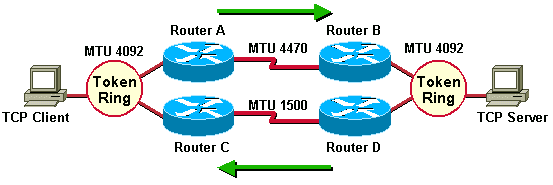
TCP MSS adjustment is required when the network operators want to ensure that the TCP packets traversing the network will not exceed a predetermined size, thus preventing any unnecessary fragmentation of TCP packets on links with small MTU. Typically this may happen on links with the MTU of 1500 bytes, when the original IP/TCP packet is encapsulated into PPPoE, GRE or any other encapsulation.
Such modification of TCP MSS size doesn't cause any observable impact on TCP session throughput because the throughput of a TCP session is predominantly dictated by the TCP window size.
TCP basics
When TCP sessions establish, they signal 2 key parameters that dictate the transfer speeds of the session. That is the MSS, the maximum size of a TCP packet and the Window size. In TCP transmission, in its basic operation is to be acknowledged. So packet transferred, receive ACK and send the next packet. This is very slow especially on long end to end delays. Windowing allows for multiple packets to be sent and using a single ACK on that window. If one packet is lost of that window, the whole window is to be retransmitted. The larger the window size is, the better for thruput, but on unreliable links, this can have an adverse affect if large windows have to be retransmitted. Also large windows require larger receive buffers on the receiving side.
So the size of the packet is dictated by the MSS. The number of packets at that size to be sent without direct ACK on each packet is the window size.
What does MSS adjust do?
MSS is the value that a TCP client signals to a server indicating what the maximum size of a packet is that it can receive. Generally this value is derived from the client's local MTU size minus 40 bytes. These 40 are composed of 20 bytes for ip header and 20 bytes for the tcp header.
The segment size refers to the actual TCP payload carried.
If there are mtu changes in the network, which can easily be seen for instance with PPPoE, which adds 8 bytes of additional header, it could lead to a client with a local MTU of 1500, signaling a TCP mss of 1460, but actually requiring 1508 bytes on a transmission line (1460 + 20 ip + 20 tcp + 8 pppoe). This will cause some hops to do fragmentation.
The TCP MSS adjust feature intercepts a TCP syn packet and scans for the first option after the tcp header. If that option is the mss size, it can re-adjust the value to the desired value configured and update the checksum along with it.
Example scenario:
Prerequisites
Basic understanding of the ASR9000 architecture and IOS-XR operating system.
Restrictions
- Feature is supported on Typhoon and Tomahawk line card generations.
- Feature is supported on BNG subscriber interfaces, on L3 dot1q sub-interfaces and on GRE tunnels. (You can't configure the ipv4 mss enable on main interfaces).
- Range of supported sizes for TCP MSS adjustment is from 1280 to 1535 bytes.
- UDP packets are obviously not subject to MSS rewrites, only the TCP SYN packet is intercepted and rewritten.
Configure
The implementation of TCP MSS adjust on ASR9000 was dictated by two factors:
- minimal performance impact when applied to an interface
- performance doesn't change with deployment scale (i.e. number of interfaces where the feature is applied)
To meet these requirements, the chosen implementation requires two configuration steps:
- specify the TCP MSS size at the network processor (NP) level.
- specify the interfaces on which the configured TCP MSS size should be applied
One consequence of this approach is that all interfaces on a given NP must use the identical value for TCP MSS adjustments.
When enabled on an interface, TCP MSS feature is applies in both directions. i.e. adjustment is applied on ingress and egress packets. Feature is applied to both IPv4 and IPv6 even if only one of them is configured.
To determine which NP controls the interface in question, use the show controllers np ports exec command.
BNG specific
For BNG which first supported the mss-adjust capability an different configuration can be used:
subscriber
pta tcp mss-adjust 1410
!
The value range for the BNG command is 1280-1536. The reason for that is that as you can see we only adjust for the higher order byte to save some space in the ucode variable.
Identifying fragmentation
Fragmentation can be identified by looking at the NP counters.
Note that for BNG and non BNG the commands and counters are different.
The reason for that is that Fragmentation is handled by NETIO for regular L3 interfaces. However BNG subscriber interfaces don't register with NETIO. This was done for scalability reasons since BNG subs don't require all the services that NETIO provides. For BNG subs, a "lite-weight" NETIO was designed called SINT (subscriber interface) that provides some basic L3 services such as access to the TCP stack, some basic ICMP support etc.
Verifying BNG subscriber fragmentation:
Looking at fragmentation at the SPP (the interupt switching path) level.
RP/0/RSP0/CPU0:A9K-BNG#show spp node-counters | i frag
Sun Mar 8 11:08:17.501 EST
ipv4_frag
Drop: Dont-fragment set: 3125 <<<< packets that have DF bit set
ipv4-frag: 3854 <<<<< packets fragmented
Verifying the NP counters with show controller np counters NP<x> location 0/<y>/CPU0
16 MDF_TX_LC_CPU 11037 107 <<<<<<<<<< 100pps to the LC CPU
17 MDF_TX_WIRE 17423 201 <<<<< 200 packets to the wire (2 frags)
21 MDF_TX_FABRIC 24798 299 <<<<<<<<<<<200 pps injected from the fab
41 PARSE_INJ_RECEIVE_CNT 17079 201 <<<<<< 200pps injected
45 PARSE_ENET_RECEIVE_CNT 8969 101 <<<<received on wire from the tester
416 RSV_PUNT_IP_MTU_EXCEEDED 9615 99 <<<<<100pps requiring frag
1048 PPPOE_FRAG_NEEDED_PUNT 9615 99 <<<<<on pppoe sessions
Verifying regular L3 fragmentation:
with the same command show controller np counters NP<x> loc 0/<y>/cpu0 the following can be observed for fragmentation:
16 MDF_TX_LC_CPU 718 106 << sent to the LC CPU for frag
33 PARSE_FAB_RECEIVE_CNT 681 100 << packets received from the fabric
416 RSV_PUNT_IP_MTU_EXCEEDED 677 100 << packets needing punt because of MTU
842 IPV4_FRAG_NEEDED_PUNT 677 100 << packets punted for FRAG reasons
Note that in both cases the DF bit is NOT assessed in the hardware, this is handled by the controlling agent, whether it be SPP for BNG subs or NETIO for regular L3 interfaces.
Configuration Example
In this example the TCP MSS adjust is applied to interface Bundle-Ether48.10.
Step 1: Determine the NP on which the TCP MSS adjust is to be configured:
RP/0/RSP0/CPU0:av-asr9001#sh bundle bundle-ether 48
<snip>
  Port                  Device           State        Port ID         B/W, kbps
  --------------------  ---------------  -----------  --------------  ----------
  Gi0/0/1/6             Local            Active       0x8000, 0x0003     1000000
      Link is Active
  Gi0/0/1/7             Local            Active       0x8000, 0x0004     1000000
      Link is Active

RP/0/RSP0/CPU0:av-asr9001#show controllers np ports all location 0/0/CPU0

                Node: 0/0/CPU0:
----------------------------------------------------------------

NP Bridge Fia                       Ports
-- ------ --- ---------------------------------------------------
0  0      0
0  0      0   TenGigE0/0/2/0, TenGigE0/0/2/1
1  1      1   GigabitEthernet0/0/1/0 - GigabitEthernet0/0/1/19
1  1      1   TenGigE0/0/2/2, TenGigE0/0/2/3
RP/0/RSP0/CPU0:av-asr9001#
Step 2: Configure the desired TCP MSS value and activate the feature on the interface Bundle-Ether48.10.
hw-module location 0/0/CPU0 tcp-mss-adjust np 1 value 1300
!
interface Bundle-Ether48.10
 ipv4 address 4.8.10.4 255.255.255.0
 ipv4 tcp-mss-adjust enable
 encapsulation dot1q 10
Verify
To verify that the feature is enabled on a selected interface, check the microcode interface descriptor block (uidb) setting:
RP/0/RSP0/CPU0:asr9001#sh uidb data location 0/0/CPU0 Bundle-Ether 48.10 ing-extension | i TCP
  TCP MSS ADJ Enable               0x1
RP/0/RSP0/CPU0:asr9001#sh uidb data location 0/0/CPU0 Bundle-Ether 48.10 extension | i TCP
  TCP MSS ADJ Enable               0x1
You can verify the rewrite with a simple TCP session on an IOS router connected to the device that is doing the MSS rewrite.
Enable debug tcp transactions and packet.
You'll see:
Feb 6 14:17:26.112: tcp0: I LISTEN 54.1.1.2:1234 81.1.1.2:23 seq 0
OPTS 4 SYN WIN 0
Feb 6 14:17:26.112: TCP0: state was LISTEN -> SYNRCVD [23 -> 54.1.1.2(1234)]
Feb 6 14:17:26.112: TCP0: tcb D333A2EC connection to 54.1.1.2:1234, received MSS 1300, MSS is 516
54.1.1.2 is the source and 81.1.1.2 is the destination. The debug is taken from 81.1.1.2
You can see that the decoded MSS value received is 1300 as per configuration on the asr9000 which sits in between client and destination. Our local MSS value is 516 which we advertise. This is merely to illustrate a possible verification of the MSS rewrite rather then focusing on the actual values.
Additional Information
It works similar in case of GRE Tunnel:
- enable under the tunnel-ip the command 'ipv4 tcp-mss-adjust enable'
- locate the exit interface the tunnel uses ((whether it be before -> traffic going into the tunnel, or after decap -> coming out of the tunnel) and then apply the corresponding 'hw-module location <> tcp-mss-adjust np X value <number>'
Related Information
- Mark as Read
- Mark as New
- Bookmark
- Permalink
- Report Inappropriate Content
@Aleksandar Vidakovic @xthuijs
We have been using your approach for these changes and it has worked really well. Question though regarding the reload as an example see below,
hw-module location 0/0/CPU0 tcp-mss-adjust np 0 value 1436
interface tenGigE 0/0/0/15
ipv4 tcp-mss-adjust enable
Normally when we make the change, we apply it at the NP level, and then the specific interface we add the "mss-adjust" command and then reload the module.
Can the MSS value be added to the NP and then reload the module, without applying it at the interface level, then later apply the "mss-adjust" command at the interface and not require a reload?
To simplify the question can we make the NP level change, reload the module, and later apply "mss-adjust" to an interface associated with the specific NP without having to reload the module?
2nd question is this and I believe the answer is yes, based on your example. We can apply the "mss-adjust" command to a Bundle interface as long as the NP level for the physical interfaces has been updated accordingly?
- Mark as Read
- Mark as New
- Bookmark
- Permalink
- Report Inappropriate Content
hi Kevin,
I'm happy to hear that you are satisfied with TCP MSS adjust functionality.
Line card reload is only required after the "hw-module ..." command. After that you can apply the TCP adjust on interfaces in any order that you like. Answer to your 2nd question is 'yes'.
best,
/Aleksandar
- Mark as Read
- Mark as New
- Bookmark
- Permalink
- Report Inappropriate Content
Hi Aleksandar, thanks very much for the quick reply! Appreciate your help!
- Mark as Read
- Mark as New
- Bookmark
- Permalink
- Report Inappropriate Content
@Aleksandar Vidakovic @Kevin Michael Pratt
Hello, for BNG just the command
subscriber
pta tcp mss-adjust 1410
is it enough? or still need hw-module location 0/0/CPU0 tcp-mss-adjust?
- Mark as Read
- Mark as New
- Bookmark
- Permalink
- Report Inappropriate Content
No support for "ipv4 tcp-mss-adjust enable" on GRE tunnel configured on NCS-55A2 platform.
interface tunnel-ip191
ipv4 tcp-mss-adjust enable
!!% 'ipv4-ma' detected the 'warning' condition 'Platform doesn't support TCP MSS Adjust on this card'
!
end
- Mark as Read
- Mark as New
- Bookmark
- Permalink
- Report Inappropriate Content
Hi Syed,
that’s correct. This feature is supported only on asr9k platform.
/Aleksandar
- Mark as Read
- Mark as New
- Bookmark
- Permalink
- Report Inappropriate Content
Thanks for confirming.
- Mark as Read
- Mark as New
- Bookmark
- Permalink
- Report Inappropriate Content
hi @isajmr ,
last time I've checked it wasn't supported even in the most recent releases. You can confirm this on the router by checking the value of the "TCP MSS ADJ" in the microcode interface descriptor block (uidb), after you have configured the "hw-module ..." command and reloaded the line card. Example:
RP/0/RSP0/CPU0:ASR-9901-A#show uidb data location 0/0/CPU0 bvi 100 ing-extension | i TCP
TCP MSS ADJ Enable 0x0
TCP MSS ADJ Enable 0x0
/Aleksandar
- « Previous
- Next »
Find answers to your questions by entering keywords or phrases in the Search bar above. New here? Use these resources to familiarize yourself with the community: