Cisco WLC’s are functionally Layer 2 non-routing devices.
Under certain circumstances, due to the underlying operating system kernel behavior, unexpected external communication may be observed.
Example:
WLC’s interfaces:
Management: vlan 2, 2.2.2.116/24
Vlan265 dynamic interface: 192.168.165.116/24
External Radius Server:
Vlan 265, 192.168.165.69
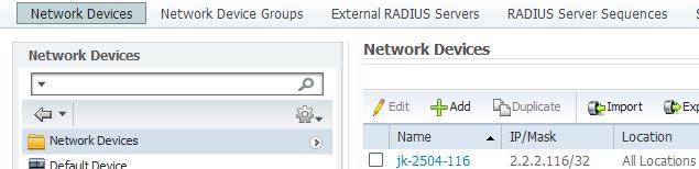
AAA Client/NAS configured for WLC’s Management Interface, 2.2.2.116:
Due to the underlying OS kernel behavior, the WLC will initiate communication with the external radius server on vlan 265 via its vlan 265 dynamic interface, regardless of configuration.
Cisco development has advised that this is expected behavior due to the fact that per RFC-1122:
“As the WLC is an IP host (not a router) (albeit a "multi-homed host"), the applicable RFC is RFC-1122. Specifically this section:
3.3.1 Routing Outbound Datagrams
The IP layer chooses the correct next hop for each datagram it
sends. If the destination is on a connected network, the
datagram is sent directly to the destination host; otherwise,
it has to be routed to a gateway on a connected network.
3.3.1.1 Local/Remote Decision
To decide if the destination is on a connected network, the
following algorithm MUST be used [see IP:3]:
(a) The address mask (particular to a local IP address for
a multihomed host) is a 32-bit mask that selects the
network number and subnet number fields of the
corresponding IP address.
(b) If the IP destination address bits extracted by the
address mask match the IP source address bits extracted
by the same mask, then the destination is on the
corresponding connected network, and the datagram is to
be transmitted directly to the destination host.
In this case, 3.3.1.1b pertains - so the packet to the host MUST be transmitted on the connected network, directly to that host.”
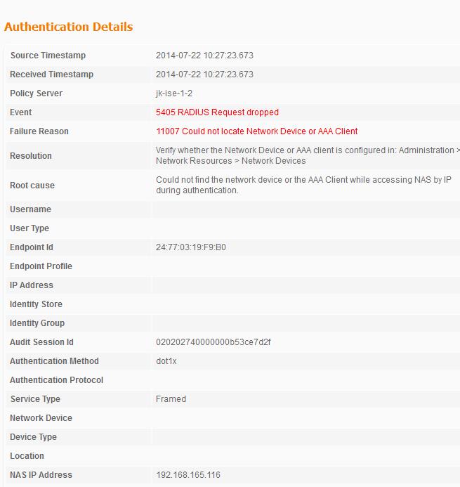
In this scenario, wireless client radius authentication will fail, as the Radius Server isn’t configured to accept authentication requests from 192.168.165.116.
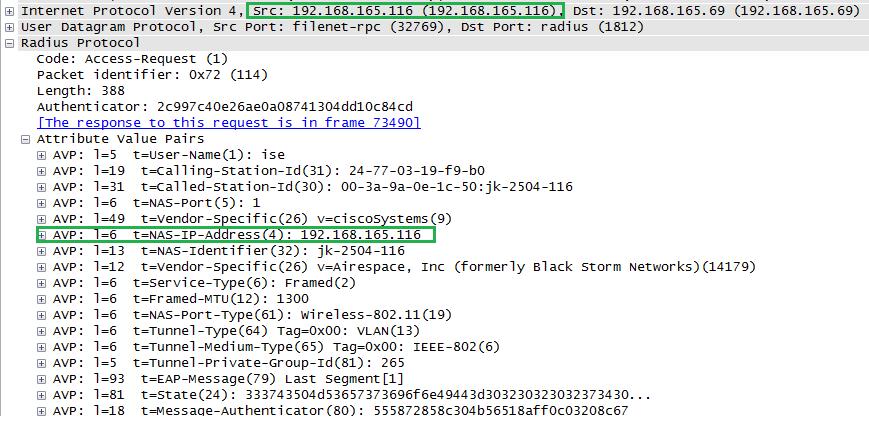
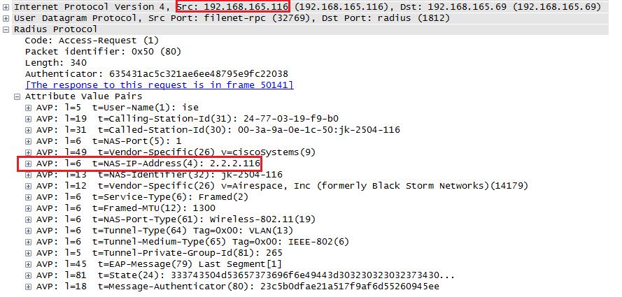
Sniffer traces show that Radius packets are being sourced by the controller via its Vlan 265 dynamic interface:
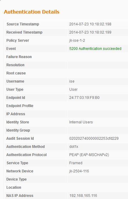
Corresponding radius server logs:
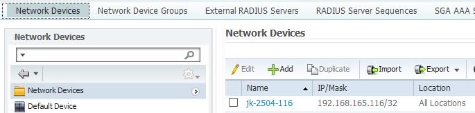
We’ll reconfigure the Radius server’s NAS entry to point to the interface that the WLC is using to communicate with it, vlan 265, 192.168.165.116:
Authentication is now successful:
Although the Radius Server’s logs reference the NAS-IP-Address attribute as 192.168.165.116, sniffer traces show that the NAS-IP-Address being sent from the controller is that of the Management interface, 2.2.2.116:
Having the NAS-IP-Address field correctly (corresponding to the sourced dynamic interface) populated in Radius packets from the controller may be required for more granular Radius server policy configurations.
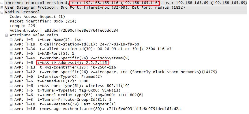
The Wlan ‘Radius Server Overwrite interface’ configuration knob forces Radius packets sourced from the Wlan’s corresponding dynamic interface to overwrite the NAS-IP-Address field to match the interface’s address:
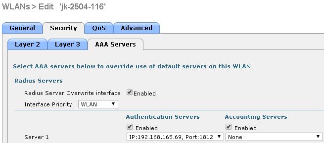
With this configuration applied, Radius packets sourced on behalf of the Wlan have the NAS-IP-Address field set to match the corresponding dynamic interface: