- Cisco Community
- Technology and Support
- Security
- Network Security
- Source and Destination NAT Issue on ASA
- Subscribe to RSS Feed
- Mark Topic as New
- Mark Topic as Read
- Float this Topic for Current User
- Bookmark
- Subscribe
- Mute
- Printer Friendly Page
Source and Destination NAT Issue on ASA
- Mark as New
- Bookmark
- Subscribe
- Mute
- Subscribe to RSS Feed
- Permalink
- Report Inappropriate Content
02-13-2013 09:54 PM - edited 03-11-2019 06:00 PM
I've been trying to find a solution to the below issue for many days but couldnt seems to get it working.
Following is the scenario.
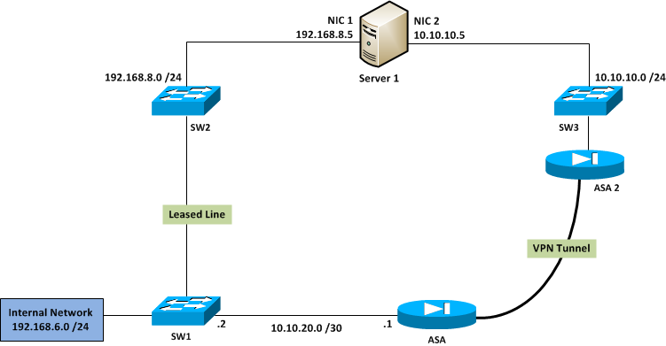
Internal network hosts (192.168.6.0/24) needs to communicate with Server 1. All internal network hosts use leased line as the primary link to connect to Server 1 using IP 192.168.8.5. Howevere, we need to implement automatic failover to VPN tunnel in case if leased line fails. That way Internal network hosts will still be able to communicate with Server 1 using 192.168.8.5 IP, but traffic should be routed via VPN tunnel.
On the ASA, VPN tunnel is configured to allow only traffic coming from 10.10.20.0 /30 and destined to 10.10.10.0 /24 to be encrypted. Therefor currenly I have implemented, all 192.168.6.0 /24 network traffic to PAT to IP 10.10.20.1 /30. I can succesfully ping from 192.168.6.0 /24 network to Server 1's IP 10.10.10.5. However, what I need is to implement destination NAT on ASA which allows Internal Network hosts to communicate with Server 1 via VPN using destination IP 192.168.8.5 /24.
Following is the current PAT configuration.
access-list internal_nat3_outbound extended permit ip 192.168.6.0 255.255.255.0 10.10.10.0 255.255.255.0
nat (Inside) 3 access-list internal_nat3_outbound
global (Outside) 3 10.10.20.1 netmask 255.255.255.255
I tried implementing both static NAT and policy NAT on the outside interface to translate 10.10.10.5 to 192.168.8.5 however, I couldn't get any of them to work. I do not have the control over ASA2 configuration as it belongs to an external party.
Any help on this is much Appreciated!!!
- Labels:
-
NGFW Firewalls

")
- Mark as New
- Bookmark
- Subscribe
- Mute
- Subscribe to RSS Feed
- Permalink
- Report Inappropriate Content
02-14-2013 06:09 AM
Destination NAT is not supported on the version of ASA that you are currently running.
You would need to upgrade your ASA to version 8.3 or above to configure destination NAT.
- Mark as New
- Bookmark
- Subscribe
- Mute
- Subscribe to RSS Feed
- Permalink
- Report Inappropriate Content
02-14-2013 01:05 PM
Hi
Destination NAT can be done without upgrading to OS version 8.3
Since 3 different networks exist on 3 branches of SW1 in your diagram, I am assuming that it's a layer 3 switch.
Now in case leased line fails you will have to figure out how the routing table updates on SW1 so that it sends all subsequent packets to ASA instead of SW2
Considering that you have that routing figured out, you can do the following
Lets say the ASA1 interface that is terminating VPN is called tunnel_int
static (tunnel_int, inside) 192.168.8.5 10.10.10.5
When packet with dst ip 192.168.8.5 is received by ASA1 on it's inside interface, above static will change dst ip from 192.168.8.5 to 10.10.10.5 and send it over tunnel_int. When reply is received from 10.10.10.5 ASA1 will change the src ip from 10.10.10.5 to 192.168.8.5 and send it back out on the inside interface, thus achieving what you are trying to do.
- Mark as New
- Bookmark
- Subscribe
- Mute
- Subscribe to RSS Feed
- Permalink
- Report Inappropriate Content
02-14-2013 07:42 PM
Jeniffer, the version on our ASA is actually 8.3
abcdrohan,
However, I did a test using the Packet Tracert feature in ASA when both inside PAT configuration (shown in initial post) and Static NAT configuration in place.
packet-tracer input Inside icmp 192.168.65.1 1 1 192.168.8.5 Phase: 1 Type: FLOW-LOOKUP Subtype: Result: ALLOW Config: Additional Information: Found no matching flow, creating a new flow Phase: 2 Type: UN-NAT Subtype: static Result: ALLOW Config: static (Outside,Inside) 192.168.8.5 10.10.10.5 netmask 255.255.255.255 match ip Outside host 10.10.10.5 Inside any static translation to 192.168.8.5 translate_hits = 0, untranslate_hits = 635 Additional Information: NAT divert to egress interface Outside Untranslate 192.168.8.5/0 to 10.10.10.5/0 using netmask 255.255.255.255 Phase: 3 Type: ACCESS-LIST Subtype: log Result: ALLOW Config: access-group Inside_access_in in interface Inside access-list Inside_access_in extended permit ip any any Additional Information: Phase: 4 Type: IP-OPTIONS Subtype: Result: ALLOW Config: Additional Information: Phase: 5 Type: INSPECT Subtype: np-inspect Result: ALLOW Config: Additional Information: Phase: 6 Type: NAT Subtype: host-limits Result: ALLOW Config: nat (Inside) 3 access-list internal_nat3_outbound match ip Inside 192.168.6.0 255.255.255.0 Outside 10.10.10.0 255.255.255.0 dynamic translation to pool 3 (10.10.20.1) translate_hits = 46240, untranslate_hits = 56506 Additional Information: Phase: 7 Type: NAT Subtype: rpf-check Result: ALLOW Config: static (Outside,Inside) 192.168.8.5 10.10.10.5 netmask 255.255.255.255 match ip Outside host 10.10.10.5 Inside any static translation to 192.168.8.5 translate_hits = 0, untranslate_hits = 635 Additional Information: Phase: 8 Type: FLOW-CREATION Subtype: Result: ALLOW Config: Additional Information: New flow created with id 2931528, packet dispatched to next module Phase: 9 Type: ROUTE-LOOKUP Subtype: output and adjacency Result: ALLOW Config: Additional Information: found next-hop 1XX.7X.1XX.2XX using egress ifc Outside adjacency Active next-hop mac address XXXX.XXXX Result: input-interface: Inside input-status: up input-line-status: up output-interface: Outside output-status: up output-line-status: up Action: allow |
As you can see from the order of the NAT, 192.168.8.5 being translated to 10.10.10.5 and then source address 192.168.6.1 also being translated to 10.10.20.1. However, packets are not being allowed in to VPN tunnel but simply forwarded via outside interface as normal traffic.
Any thoughts why is this happening?
- Mark as New
- Bookmark
- Subscribe
- Mute
- Subscribe to RSS Feed
- Permalink
- Report Inappropriate Content
02-14-2013 09:51 PM
Hi Guys,
Thanks for your support and help on this. I was able to resolve the issue. I had to add an ACL entry to
internal_nat3_outbound access list as follows.
access-list internal_nat3_outbound extended permit ip 192.168.6.0 255.255.255.0 host 192.168.81.4
- Mark as New
- Bookmark
- Subscribe
- Mute
- Subscribe to RSS Feed
- Permalink
- Report Inappropriate Content
02-15-2013 09:16 AM
Does it send over vpn interface when outside int is down?
With your packet tracer test was outside int down or up when you ran it? Should be run when outside int is down so that routing happens correctly
Discover and save your favorite ideas. Come back to expert answers, step-by-step guides, recent topics, and more.
New here? Get started with these tips. How to use Community New member guide
