- Cisco Community
- Technology and Support
- Networking
- Networking Knowledge Base
- Load balancing using Performance Routing pfr/OER
- Subscribe to RSS Feed
- Mark as New
- Mark as Read
- Bookmark
- Subscribe
- Printer Friendly Page
- Report Inappropriate Content
- Subscribe to RSS Feed
- Mark as New
- Mark as Read
- Bookmark
- Subscribe
- Printer Friendly Page
- Report Inappropriate Content
12-25-2009 01:57 AM - edited 03-01-2019 04:29 PM
Introduction:
Cisco Performance Routing pfr is one of the most intelligent Cisco IOS services that can handle traffic routing automatically to achieve the most reliable and none stop traffic forwarding between sites and over multiple routers and links.
Cisco pfr optimizes routing and route selection based on real time measurements of the available paths and select the best path with regard to the defined polices, such as traffic delay, jitter or link utilization, which make it more flexible and convenient especially with the implementations of converged networks (Voice, Video and DATA).
Using only a standard dynamic routing protocol such as BGP with two ISPs, if one of the ISPs experiencing problems inside the SP network and a company has real time sensitive traffic this will make some issues such delay, jitter and/or packet loss, while from BGP perspective the other BGP peer is reachable and the BGP session is up.
With Cisco pfr the router now will be able to measure the traffic over all the available ISPs/paths, this measurement will be done by the edge routers that taking the role of a border router BR in pfr terminologies, while another router (either dedicated or co-existed in one of the BRs) will be the decision maker and all the BR will report the traffic measurements to it and this router called Master Controller MC, which works exactly as the brain of the pfr.
If any ISP link experiencing any problem such delay or jitter the BR connected to that ISP will report the traffic measurement to the MC and the MC will compare it to a predefined policy, if its considered out of policy OOP then the MC will start looking for another external link within the BRs that has better or in policy path, and there are several timers that can be configured and tuned such as bakoff timer to avoid route flapping and periodic interval which is the periodic time in minutes that the MC router start learn prefixes with a default value of 120 minute.
For more details please refer to the following link:
Performance Routing Q&A
Configuration Example:
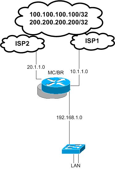
In this configuration example we will see how we can configure load balancing by using pfr in one edge router this edge router has two external links represent WAN or Internet links ( both are valid options) and this edge router configured as BR router and MC router.
the routing configuration is very simple only two defual routes each point to one of the ISP’s next hop IP.
ip route 0.0.0.0 0.0.0.0 10.1.1.10
ip route 0.0.0.0 0.0.0.0 20.1.1.10
EDGE_RTR#show ip route
Gateway of last resort is 20.1.1.10 to network 0.0.0.0
1.0.0.0/24 is subnetted, 1 subnets
C 1.1.1.0 is directly connected, Loopback0
20.0.0.0/24 is subnetted, 1 subnets
C 20.1.1.0 is directly connected, FastEthernet1/1
10.0.0.0/24 is subnetted, 1 subnets
C 10.1.1.0 is directly connected, FastEthernet1/0
C 192.168.1.0/24 is directly connected, FastEthernet2/0
S* 0.0.0.0/0 [1/0] via 20.1.1.10
[1/0] via 10.1.1.10
The criteria will be used here to do load balancing is link utilization, first we need to define the border router and basic MC configurations
interface Loopback0
ip address 1.1.1.1 255.255.255.0
key chain OER ---- for authentication
key 1
key-string oerkey
MC part:
oer master
max-range-utilization percent 2 ---- 2% only for this example ( if the range between external links utilization over 2 % then the MC will start to distribute the load between the links with regard to the max link utilization configured bellow as will )
logging
!
border 1.1.1.1 key-chain OER ----- local loopback as both BR and MC co-existed
interface FastEthernet1/1 external
max-xmit-utilization absolute 5 --- this means max utilization for this link 5 K ( just for the purpose of this example to see the link out of policy quickly )
interface FastEthernet1/0 external
max-xmit-utilization absolute 50 --- 50k ( this value for this example only )
interface FastEthernet2/0 internal
!
learn
throughput
periodic-interval 0 --- configured 0 to make sure all the time the router will learn prefixes ( for the purpose of this example only)
aggregation-type prefix-length 32 -- automatic aggregation of the prefixes that will be created by the MC automatically will have a prefix length with /32 in this example
mode route control
mode route metric static tag 2000 --- automatic static route entries created by the MC will have route tag as 2000
mode select-exit best --- always select the best in policy exit
resolve range priority 1 --- policy measurement criteria will give utilization range priority 1
resolve utilization priority 2 variance 1 --- link utilization priority 2
BR part:
oer border
local Loopback0 -- same ip address used in the MC part config for this BR
master 1.1.1.1 key-chain OER
!
EDGE_RTR#show oer master border
Border Status UP/DOWN AuthFail
1.1.1.1 ACTIVE UP 01:09:11 0
as it shown earlier in this document the routing table has only two static default routes each one points to a different ISP/ next hop
Now lets generate traffic from the inside network to simulate internal traffic and as we configured the link utilization of interface fa1/1 to a low value this interface will be considered OOP quickly
EDGE_RTR#show oer master prefix
EDGE_RTR#
: %OER_MC-5-NOTICE: Load OOP BR 1.1.1.1, i/f Fa1/1, load 24
policy 5
%OER_MC-5-NOTICE: Exit 1.1.1.1 intf Fa1/1 OOP, Tx BW 24, R
x BW 24, Tx Load 0, Rx Load 0
EDGE_RTR#show oer master prefix
Prefix State Time Curr BR CurrI/F Protocol
PasSDly PasLDly PasSUn PasLUn PasSLos PasLLos
ActSDly ActLDly ActSUn ActLUn EBw IBw
--------------------------------------------------------------------------------
100.100.100.100/32 DEFAULT* @29 1.1.1.1 Fa1/1 U
U U 0 0 0 0
U U 0 0 25 25
EDGE_RTR#
%OER_MC-5-NOTICE: Discovered Exit for prefix 100.100.100.100/32, BR 1.1.1.1, i/f Fa1/1
EDGE_RTR#show oer border routes static
Flags Network Parent Tag
CE 100.100.100.100/32 0.0.0.0/0 2000
EDGE_RTR#show ip route 100.100.100.100
Routing entry for 100.100.100.100/32
Known via "static", distance 1, metric 0
Tag 2000
Routing Descriptor Blocks:
* 10.1.1.10
Route metric is 0, traffic share count is 1
Route tag 2000
As it shown above a static route entry has been created automatically with a prefix length of /32 based on the prefix aggregation length specified in the MC config
Also the route tag is 2000 which is the tag value configured in the MC config as well, this tag maybe useful for redistribution or route filtering
Also the most important thing is that the created static route entry for the prefix 100.100.100.100/32 is through the Fa1/0
Because the first used link was fa1/1 and according to the previous logging message this link flooded with traffic and considered out of policy
: %OER_MC-5-NOTICE: Load OOPBR 1.1.1.1, i/f Fa1/1, load 24
policy 5
then the MC has chosen fa1/0 because it is not over utilized ( in policy )
now lets generate traffic again to over utilize fa1/0 :
%OER_MC-5-NOTICE: Load OOPBR 1.1.1.1, i/f Fa1/0, load 53
policy 50
%OER_MC-5-NOTICE: Exit 1.1.1.1 intf Fa1/0 OOP, Tx BW 53, R
x BW 53, Tx Load 0, Rx Load 0
New learned prefixes:
Prefix State Time Curr BR CurrI/F Protocol
PasSDly PasLDly PasSUn PasLUn PasSLos PasLLos
ActSDly ActLDly ActSUn ActLUn EBw IBw
--------------------------------------------------------------------------------
200.200.200.200/32 DEFAULT* @74 1.1.1.1 Fa1/0 U
U U 0 0 0 0
U U 0 0 29 28
100.100.100.100/32 INPOLICY 0 1.1.1.1 Fa1/0 STATIC
U U 0 0 0 0
U U 0 0 0 0
%OER_MC-5-NOTICE: Discovered Exit for prefix 200.200.200.200/32, BR 1.1.1.1, i/f Fa1/0
EDGE_RTR#show oer border routes static
Flags: C - Controlled by oer, X - Path is excluded from control,
E - The control is exact, N - The control is non-exact
Flags Network Parent Tag
CE 100.100.100.100/32 0.0.0.0/0 2000
CE 200.200.200.200/32 0.0.0.0/0 2000
EDGE_RTR#show ip route
200.200.200.0/32 is subnetted, 1 subnets
S 200.200.200.200 [1/0] via 20.1.1.10
1.0.0.0/24 is subnetted, 1 subnets
C 1.1.1.0 is directly connected, Loopback0
100.0.0.0/32 is subnetted, 1 subnets
S 100.100.100.100 [1/0] via 10.1.1.10
20.0.0.0/24 is subnetted, 1 subnets
C 20.1.1.0 is directly connected, FastEthernet1/1
10.0.0.0/24 is subnetted, 1 subnets
C 10.1.1.0 is directly connected, FastEthernet1/0
C 192.168.1.0/24 is directly connected, FastEthernet2/0
S* 0.0.0.0/0 [1/0] via 20.1.1.10
[1/0] via 10.1.1.10
It obvious from the above routing table we have two new static routes entries crated automatically by the MC each one point to a different next hop based on the link's utilization policy configuration. Here we achieved load balancing over tow links by using pfr.
.
Note:
You can implement NAT with this solution if its required by using ACLs and route maps
This example was configured and working with NAT:
EDGE_RTR#show ip nat translations
Pro Inside global Inside local Outside local Outside global
icmp 20.1.1.1:84 192.168.1.1:84 200.200.200.200:84 200.200.200.200:84
icmp 10.1.1.1:85 192.168.1.1:85 100.100.100.100:85 100.100.100.100:85
EDGE_RTR#
For a configuration example of using NATing with two links and route maps please see the document bellow:
https://supportforums.cisco.com/docs/DOC-8313
This was a simple pfr configuration example; with pfr you can configure more complex policies and measurements with active and/or passive monitoring using echo, tcp or udp props in conjunction with ip sla, also you can use a dynamic routing protocol instead of static routing such as BGP.
Thank you
Marwan Alshawi
- Mark as Read
- Mark as New
- Bookmark
- Permalink
- Report Inappropriate Content
Please see Cisco's new solution for load-balancing:
ITD: Load Balancing, Traffic Steering & Clustering using Nexus 5k/6k/7k
ITD (Intelligent Traffic Director) is a hardware based multi-Tbps Layer 4 load-balancing, traffic steering and clustering solution on Nexus 5k/6k/7k series of switches. It supports IP-stickiness, resiliency, NAT (EFT), VIP, health monitoring, sophisticated failure handling policies, N+M redundancy, IPv4, IPv6, VRF, weighted load-balancing, bi-directional flow-coherency, and IPSLA probes including DNS. There is no service module or external appliance needed. ITD provides order of magnitude CAPEX and OPEX savings for the customers. ITD is available on Nexus series of switches. ITD is much superior than legacy solutions like PBR, WCCP, ECMP, port-channel, layer-4 load-balancer appliances.
- Mark as Read
- Mark as New
- Bookmark
- Permalink
- Report Inappropriate Content
Is it working Per Outgoing / Incomming Traffic ?
- Mark as Read
- Mark as New
- Bookmark
- Permalink
- Report Inappropriate Content
Dear ,
can we use pfr here to run inbound load balancing ?
- « Previous
-
- 1
- 2
- Next »
Find answers to your questions by entering keywords or phrases in the Search bar above. New here? Use these resources to familiarize yourself with the community:
