- Cisco Community
- Technology and Support
- Security
- Security Knowledge Base
- Cisco IPS Initialization, Inline, & Managed
- Subscribe to RSS Feed
- Mark as New
- Mark as Read
- Bookmark
- Subscribe
- Printer Friendly Page
- Report Inappropriate Content
- Subscribe to RSS Feed
- Mark as New
- Mark as Read
- Bookmark
- Subscribe
- Printer Friendly Page
- Report Inappropriate Content
11-16-2011 06:40 PM - edited 03-08-2019 06:43 PM
In this month's Chalk Talk, Dave Burns and Odunayo Adesina discuss deciding how and where to use the Cisco IPS, how to get it initialized/inline, and how to manage it quickly.
The task of deploying a network IPS (Intrusion Prevention System) device can be quite overwhelming for a network or security professional that hasn’t done it before. The first and most important step in deploying a network IPS device is understanding the various modes and which mode applies to the deployment at hand. The following modes are supported on the Cisco IPS sensors:
- Promiscuous Mode
- Inline Interface Pair Mode
- Inline VLAN Pair Mode
- Inline VLAN Group Mode
- Selective Inline Analysis Mode
All of these modes are discussed in great detail in the online configuration guides found on Cisco.com. In this article we’ll first focus on the most commonly deployed Inline mode, which Is Inline Interface Pair Mode. Figure 1 shows an example at a high level of how an Inline VLAN Pair Mode is commonly deployed around the world today.
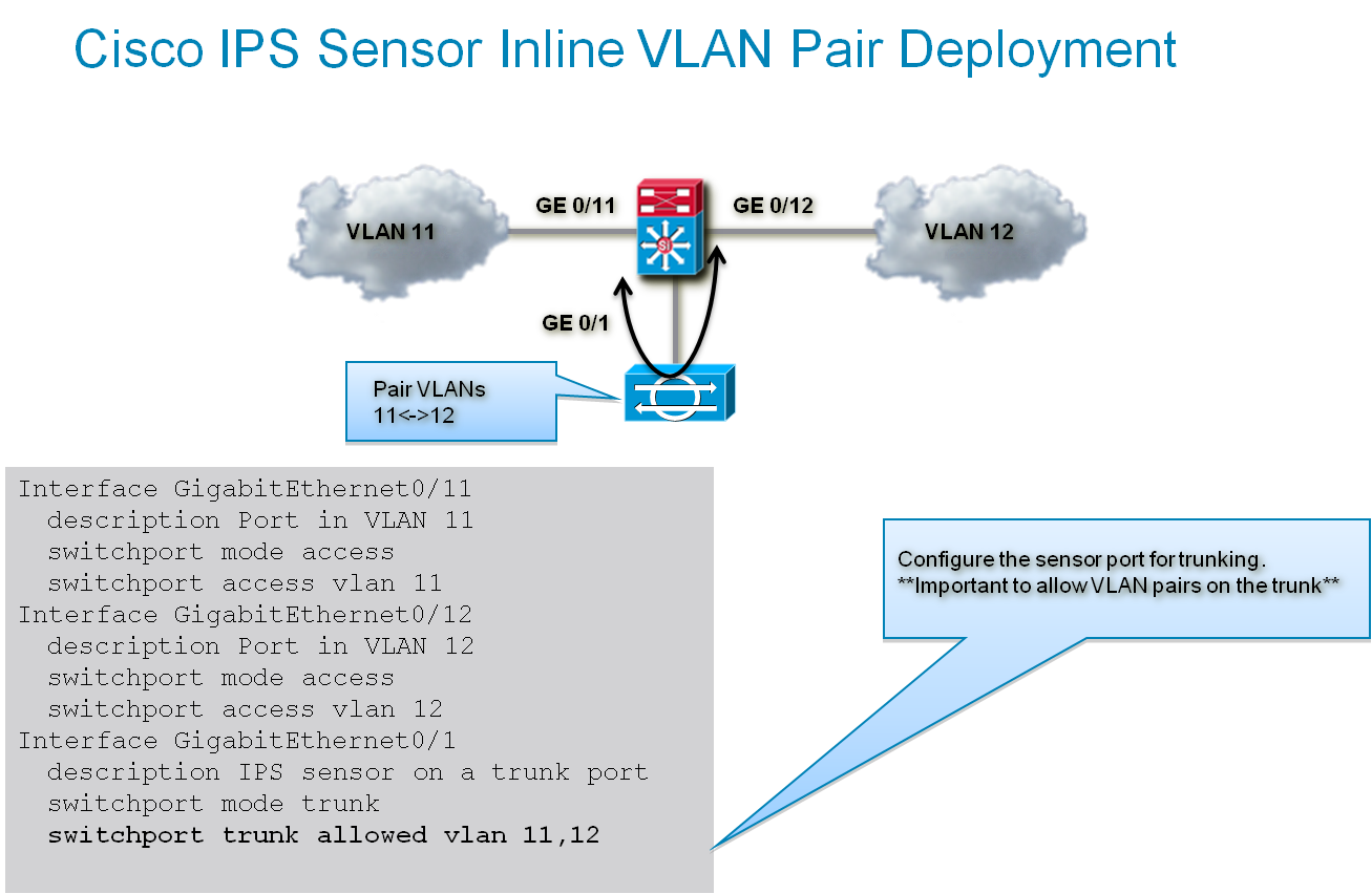
Figure 1: Inline VLAN Pair Mode Examples
Initialization
Before administrators/engineers can put the sensor in any mode or even manage it, they first must initialize the sensor. The steps below can also be found in the Cisco IPS Configuration guide on Cisco.com. It is highly recommended that administrators pay special attention to any notes found in the configuration guides in addition to the steps below.
- Log into the sensor via CLI (Command Line Interface). The default username and password are “cisco” (without quotations). It’s important to note that the sensor will prompt you to change the default password, after which the basic setup begins.
- Enter the “setup” command (without quotations). The System Configuration Dialog is displayed.
- Specify the hostname, which is case sensitive and supports up to 64 characters (spaces are not supported). The default is sensor.
- Specify the IP interface in the form of IP Address/Netmask,Gateway.: X.X.X.X/nn,Y.Y.Y.Y,
- Enter “yes” to modify the network access list, and enter the IP address and netmask of the network you want to add to the access list. It’s important to include the IP address or addresses that will be accessing the sensor via the IDM (IPS Device Manager), IME (IPS Manager Express), remote network, etc.
- DNS server or an HTTP proxy server for Global Correlation to work must be configured. This step can be done later if necessary too.
- Enter “yes” to modify the time or “no” so accept the default parameters.
- Enter “off”, “partial”, or “full” to participate in the SensorBase Network Participation followed by “yes” to participate in the SensorBase Network.
- Dialogue will scroll through reflecting these changes, at the end followed by the keyword “exit” there are three options [0 – 3], select option “2” to save the configuration.
- Select “yes” to reboot the sensor.
The sensor is now initialized and ready for further configuration.
Inline Interface Pair Mode
Now that the sensor is initialized, the sensor is now ready for interface configurations. The following steps were taken from the Cisco IPS Configuration Guide, and summarized for the purposes of this article.
- Assuming the administrator is logged into the sensor via CLI, type the “setup” command. The system configuration dialogue is displayed.
- Enter “3” to access advanced setup.
- Specify the Telnet server status, which is disabled by default.
- Specify the TCP port used by the web server, which is by default 443. Without this defined, the IME and IDM gui will not work.
- Enter “yes” to modify the interface and virtual sensor configuration and to see the current interface configuration.
- At the end of the output there are three options [0-2], select option 1 to edit the interface configuration.
- Enter “2” to add inline VLAN pairs and display the list of available interfaces.
- Enter “2” to add an inline VLAN pair to GigabitEthernet0/1.
- Enter a subinterface number and description.
- Enter numbers for VLAN 1 and 2, which in the examples would be VLANs 11 and 12. Press “Enter” to return to the available interfaces menu.
- At this point you can either configure another interface or press “Enter” to return to the top-level interface editing menu. Continue this step until the “Edit Interface Configuration” is one of the menu options.
- Enter “2” to edit the virtual sensor configuration.
- Enter “2” to modify the virtual sensor configuration, vs0. The virtual sensor configuration dialogue will be displayed.
- Enter “3” to add inline VLAN pair GigabitEthernet0/1:1
- Press “Enter” to return to the top-level virtual sensor menu followed by “Enter” again to return to the top-level interface and virtual sensor configuration menue.
- Enter “yes” if you want to modify the default threat prevention settings and “yes” again to disable automatic threat prevention on all virtual sensors.
- Press “Enter” to exit the interface and virtual sensor configuration. The configuration dialogue will be displayed again that was modified.
- Enter “2” to save the configuration.
- Enter “yes” to continue reboot.
The Cisco IPS sensor is now configured for Inline VLAN Pair Mode as the example in Figure 1 shows.
Managed
With the initial setup of the IPS completed above, further configuration, management, and monitoring can be done using the Cisco IPS Manager Express (IME). To download IME, go to the url www.cisco.com/go/ime and follow the instructions to install.
After it is installed, complete the following steps:
- Launch the IME application and, once in the Home View, click on Devices > Device List and then on Add. The Add Device window is displyed.
- In the window, put in the required information in the following fields:
- Sensor Name.
- Sensor IP Address
- User Name
- Password
- Web Server Port
Note: There are options to choose to connect using https or http. If you choose https, the sensor will present you with a certificate which, once you verify and accept, is stored locally for future use during connections to the Sensor. There are also options to pull in most recent events, specify a specific time interval, or exclude some events.
3. After all the parameters have been entered, click OK. Figure 2 below shows the Add Device window pop-up from IME..
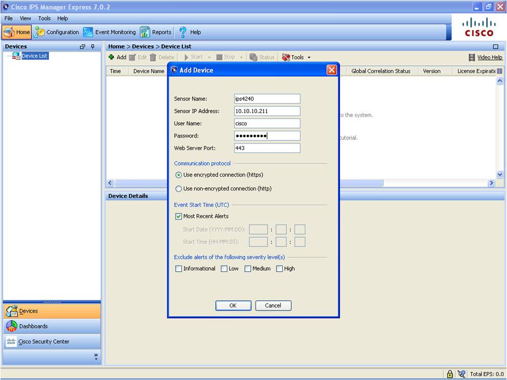 Figure2: Adding IPS Sensors to Cisco IME
Once connected, the Sensor is displayed in the Device list with information related to the Sensor such as Time, Device Name, IP Address, Device Type, Event Status, Sensor Health, Global Correlation Status, version, License Expiration, Load, Memory, CPU and Signature Version. More details can be obtained in the Device Details pane. This altogether provides information at a glance.
To get a detailed presentation of this information, from the Home View, click on Dashboards (Home > Dashboards > Dashboard) as shown in Figure 3 below:
 Figure 3: Monitoring IPS Sensors using Cisco IME
The Health Dashboard and the Events Dashboard are pre-populated with Gadgets by default. More Gadgets can be added to either of the dashboards and a customizable dashboard can be added by clicking on Add Dashboard located next to Video Help in the top right of the Dashboard pane.
Conclusion
In this article we briefly discussed the Cisco IPS sensor and one of the most commonly deployed modes of operation. We also discussed a method of managing the sensor once it is deployed. The Cisco IPS sensor is quite versatile and isn’t a one size fits all, so it’s important to follow the best practices around discovery, design, planning, etc. As a best practice for any product deployment, review the data sheets, design guides, and configuration guides available on Cisco.com.
CCNP Security IPS 642-627 Official Cert Guide
By David Burns, Odunayo Adesina, Keith Barker
ISBN-10: 1-58714-255-4
ISBN-13: 978-1-58714-255-0
Published: October 25, 2011
US SRP: $55.99
Published by Cisco Press.
Find answers to your questions by entering keywords or phrases in the Search bar above. New here? Use these resources to familiarize yourself with the community: