- Cisco Community
- Technology and Support
- Security
- Security Knowledge Base
- Firepower Threat Defense (NGIPSv) for ISR 4K & G2 - IPS inline mode using VRF method
- Subscribe to RSS Feed
- Mark as New
- Mark as Read
- Bookmark
- Subscribe
- Printer Friendly Page
- Report Inappropriate Content
- Subscribe to RSS Feed
- Mark as New
- Mark as Read
- Bookmark
- Subscribe
- Printer Friendly Page
- Report Inappropriate Content
06-20-2016 10:29 AM - edited 03-08-2019 06:59 PM
- Prerequisite and code download links
- Goal
- Limitations
- Supported ISR and UCS-E Model
- Supported ISRG2 and UCS-E Blades:
- Supported ISR4K and UCS-E Blades:
- Topology
- Simple Topology
- How Firepower Works
- Step by Step ISR 4K Configuration
- Configure CIMC
- Setting up ESXi
- Setting up Firepower and Firepower Management Center VMs
- Add license to the FireSIGHT Management Center
- Router Configuration and Topology
- ISR 4K Topology
- ESXi NIC mapping
- Relevant ISR4K Configuration
- ISR G2 Topology
- ESXi NIC mapping
- Relevant ISR G2 Configuration
- Fail Open using IP SLA (ISR 4K topology)
- Troubleshooting
This configuration example is meant to be interpreted with the aid of the documentation from the configuration guide attached to this document.
UCS-E configuration guide: http://www.cisco.com/c/en/us/td/docs/unified_computing/ucs/e/2-0/gs/guide/b_2_0_Getting_Started_Guide.html
Firepower Virtual Appliance and Defense Center Data Sheet: https://na8.salesforce.com/sfc/p/#80000000dRH9KXPLJqkSwWBoW3e_vtLbnXOyiNg=
Firepowe 3D System Virtual Installation Guide 5.3: http://www.cisco.com/c/en/us/support/security/ngips-virtual-appliance/tsd-products-support-series-home.html
Firepowe Management Center configuration guide: http://www.cisco.com/c/en/us/support/security/defense-center-virtual-appliance/tsd-products-support-series-home.html
UCS-E Troubleshooting guide: http://www.cisco.com/c/en/us/td/docs/unified_computing/ucs/e/ts/guide/e_series_ts.html
Prerequisite and code download links
ISR must run XE image 3.14 or above. Download here: http://software.cisco.com/download/release.html?mdfid=284389362&flowid=71903&softwareid=282046477&release=3.12.2S&relind=AVAILABLE&rellifecycle=ED&reltype=latest
Firepower Management Center VM Download:
https://software.cisco.com/download/release.html?mdfid=286259687&softwareid=286271056&release=5.4.1.6&relind=AVAILABLE&rellifecycle=&reltype=latest
Firepower Sensor VM Download:
https://software.cisco.com/download/release.html?mdfid=286259690&softwareid=286271056&release=5.3.0.8&relind=AVAILABLE&rellifecycle=&reltype=latest
ESXi 5.0 or above. You can download VMWare customized image for Cisco here:
https://my.vmware.com/web/vmware/details?downloadGroup=CISCO-ESXI-5.1.0-GA-25SEP2012&productId=284
UCS-E140D and UCS-E160 Images: http://software.cisco.com/download/release.html?mdfid=284479266&softwareid=284480160&release=2.1.0&flowid=34485
UCS-E140S Images: http://software.cisco.com/download/release.html?mdfid=284479227&softwareid=284480160&release=2.1.0&flowid=34482
UCS-E120S Images: http://software.cisco.com/download/release.html?mdfid=286231777&flowid=50083&softwareid=284480160&release=2.2.2&relind=AVAILABLE&rellifecycle=&reltype=latest
BDI Doc in IOS-XE: http://www.cisco.com/c/en/us/td/docs/routers/asr1000/configuration/guide/chassis/asrswcfg/bdi.html
Goal
Is to implement Firepower on the UCS-E blade on ISR 4K using the VRF method
Limitations
Please read this link:
L-7 inspections in ZBF
QoS
PBR
Supported ISR and UCS-E Model
Supported ISRG2 and UCS-E Blades:
|
ISR Platform |
Cisco UCS EN120E |
Cisco UCS EN140N |
Cisco UCS EN120S and E140S |
Cisco UCS E140D and E160D-M2 |
Cisco UCS E160D-M1 and E180D |
|
1921 |
1 |
No |
No |
No |
No |
|
1941 |
1 |
No |
No |
No |
No |
|
2901 |
2 |
No |
No |
No |
No |
|
2911 |
2 |
No |
1 |
No |
No |
|
2921 |
2 |
No |
1 |
1 |
No |
|
2951 |
2 |
No |
2 |
1 |
No |
|
3925 |
2 |
No |
2 |
1 |
1 |
|
3945 |
2 |
No |
4 |
1 |
1 |
|
3925E |
1 |
No |
2 |
1 |
1 |
|
3945E |
1 |
No |
4 |
1 |
1 |
Supported ISR4K and UCS-E Blades:
|
ISR Platform |
Cisco UCS EN120E |
Cisco UCS EN140N |
Cisco UCS EN120S and E140S |
Cisco UCS E140D and E160D-M2 |
Cisco UCS E160D-M1 and E180D |
|
4321 |
No |
2 |
No |
No |
No |
|
4331 |
No |
2* |
1 |
No |
No |
|
4351 |
No |
3* |
2 |
1 |
1 |
|
4431 |
No |
3 |
No |
No |
No |
|
4451 |
No |
3* |
2 |
1 |
1 |
Topology
Simple Topology
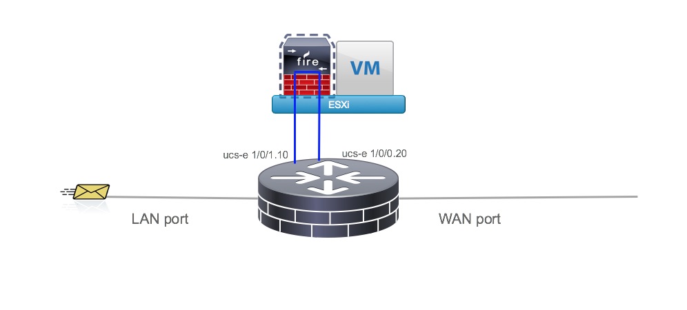
How Firepower Works
Host the Sensor on the UCS-E
- IPS is in inline mode
- Packets ingress via the LAN interface of the router
- SF sensor examines traffic; allowed packets egress the WAN interface of the router
Step by Step ISR 4K Configuration
Configure CIMC
Refer the steps here: https://www.cisco.com/c/en/us/support/docs/security/firepower-management-center/200366-Configure-FirePOWER-Services-on-an-ISR-D.html#anc13
Upgrade CIMC to the latest firmware
For XE image 3.14 and above CIMC should be running 2.3 or above
For ISR IOS image 15.5(1)T and above CIMC should be running 2.3 or above
Launch CIMC GUI on the browser from the laptop with the default userID and pasword.
userID: admin and password: password
Download the latest CIMC HUU and upgrade the BIOS, CIMC and other firmware components per this link: http://www.cisco.com/c/en/us/td/docs/unified_computing/ucs/e/2-0/gs/guide/b_2_0_Getting_Started_Guide/b_2_0_Getting_Started_Guide_chapter_01010.html#task_B4052C8757D74555A073C0BD759B211D
Setting up ESXi
Install VSphere Client
Refer this link: https://www.cisco.com/c/en/us/support/docs/security/firepower-management-center/200366-Configure-FirePOWER-Services-on-an-ISR-D.html#anc16
Setting up Firepower and Firepower Management Center VMs
Refer this link: https://www.cisco.com/c/en/us/support/docs/security/firepower-management-center/200366-Configure-FirePOWER-Services-on-an-ISR-D.html#anc16
Configure VSwitch interfaces on ESXi
Refer this link: https://www.cisco.com/c/en/us/support/docs/security/firepower-management-center/200366-Configure-FirePOWER-Services-on-an-ISR-D.html#anc16
Both UCS-E interfaces on the ISR4K are trunk ports.
UCS-E 120S and 140S, have 3 Network Adaptor + Mgmt Port
vmnic0 is mapped to UCSEx/0/0 on the router backplane
vmnic1 is mapped to UCSEx/0/1 on the router backplane
vmnic2 is mapped to UCS-E front plane GE2 interface
front-panel management (M) port can only be used for CIMC
UCS-E 140D, 160D, and 180D have 4 Network Adaptor:
vmnic0 is mapped to UCSEx/0/0 on the router backplane
vmnic1 is mapped to UCSEx/0/1 on the router backplane
vmnic2 is mapped to UCS-E front plane GE2 interface
vminc3 is mapped to UCS-E front plane GE3 interface
front-panel management (M) port can only be used for CIMC
Spin a FireSIGHT VM and configure it
Follow the link and instructions provided on the ISR 4K link. Just change the IP addressing appropriate to the ISR G2 topology.
Add the FireSIGHT to the Sensor VM
Follow the link and instructions provided on the ISR 4K link. Just change the IP addressing appropriate to the ISR G2 topology.
Add the Sensor to the FireSIGHT
Follow the link and instructions provided on the ISR 4K link. Just change the IP addressing appropriate to the ISR G2 topology.
Add license to the FireSIGHT Management Center
Refer this link: https://www.cisco.com/c/en/us/support/docs/security/firepower-management-center/200366-Configure-FirePOWER-Services-on-an-ISR-D.html#anc16
Router Configuration and Topology
ISR 4K Topology
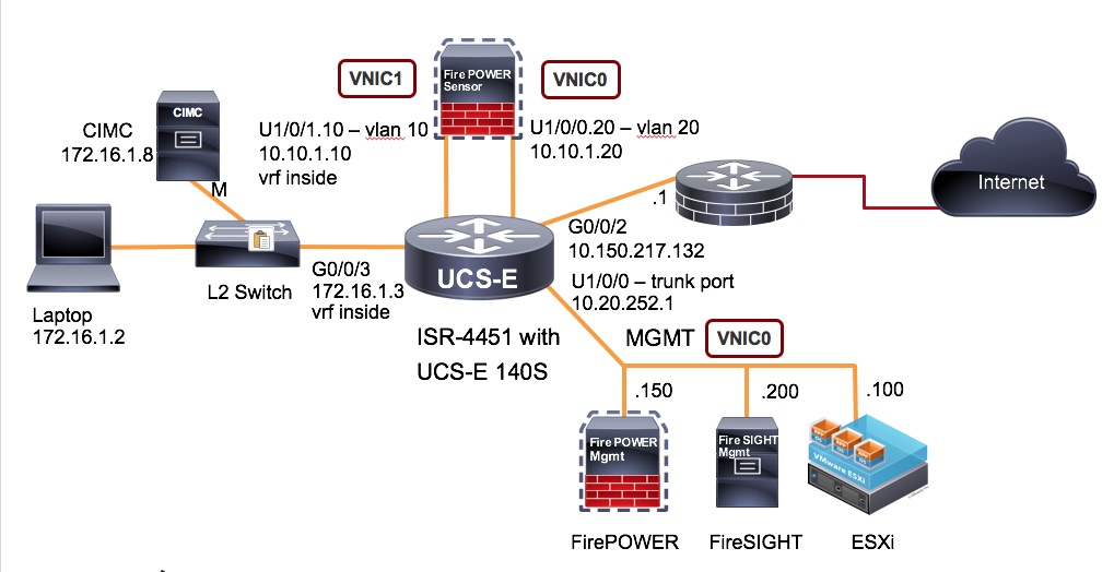
Identify 3 separate vlans to use for the following:
- ESXi and Firepower Sensor management (separate subnet) Native Vlan
- Firepower Inside (separate subnet) Vlan 10
- Firepower Outside (same subnet as Firepower Inside) Vlan 20
ESXi NIC mapping
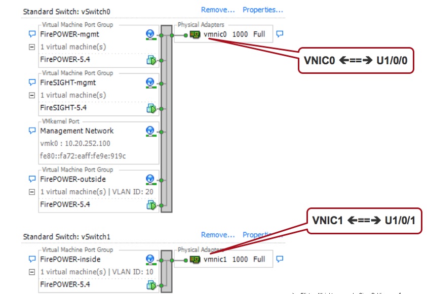
In this case:
- Management for ESXi and Firepower Sensor is in Vlan 1 (u1/0/0) <==> vnic 0
- Firepower Sensor Inside is on Vlan 10 (u1/0/1.10) <==> vnic 1
- Firepower Sensor Outside is on Vlan 20 (u1/0/0.20) <==> vnic 0
Relevant ISR4K Configuration
Inside Interface Configuration (in a vrf)
interface GigabitEthernet0/0/3
description LAN sideip vrf forwarding inside
ip address 172.16.1.3 255.255.255.0
!
UCS-E sub-interface also in the same vrf (inside of the sensor)
interface ucse1/0/1.10
description LAN side Firepower
encapsulation dot1Q 10
ip vrf forwarding inside
ip address 10.10.1.10 255.255.255.0
!
Default route for the vrf to get to the other side of the sensor in order to reach the internet.
 ip route vrf inside 0.0.0.0 0.0.0.0 10.10.1.20
!
Route to get to ESXi, Firepower and Firesight mgmt
ip route vrf inside 10.20.252.0 255.255.255.0 ucse1/0/1 10.10.1.20
!
UCS-E sub-interface in the global (outside of the sensor)
interface ucse1/0/0.20
description WAN side Firepower
encapsulation dot1Q 20
ip address 10.10.1.20 255.255.255.0
ip nat inside
!
Outside Interface facing the Internet
interface GigabitEthernet0/0/2
description WAN side
ip address 10.150.217.132 255.255.255.0
ip nat outside
!
NAT statement to PAT the inside hosts to look like the G0/0/2 interface IP address
ip nat inside source list nat-acl interface GigabitEthernet0/0/2 overload
!
Default route on the global side to reach the internet
ip route 0.0.0.0 0.0.0.0 10.150.217.1
!
ISR G2 Topology
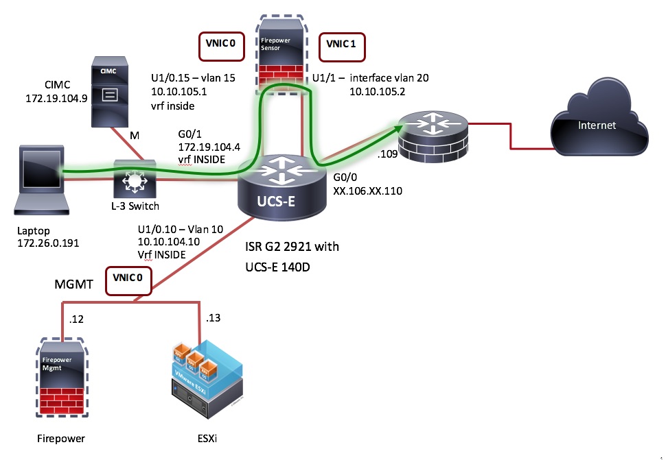
Identify separate vlans to use for the following:
- ESXi and Firepower Sensor management (separate subnet) Vlan 10
- Firepower Inside (separate subnet) Vlan 15
- Firepower Outside (same subnet as Firepower Inside) Vlan 20
ESXi NIC mapping
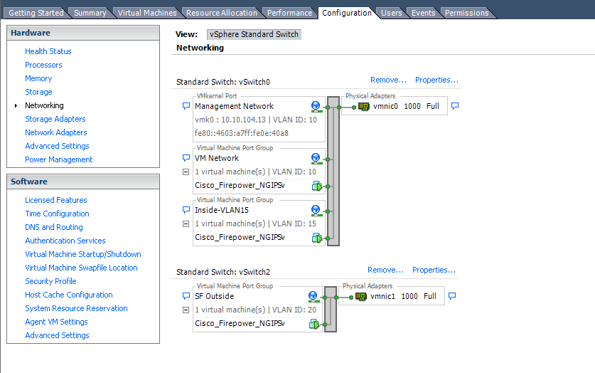
In this case:
- Management for ESXi and Firepower Sensor is in Vlan 10 (u1/0.10) <==> vnic 0
- Firepower Sensor Inside is on Vlan 15 (u1/0.15) <==> vnic 0
- Firepower Sensor Outside is on Vlan 20 (int vlan 20) <==> vnic 1
Note: In case of ISR G2 we can carve out sub interfaces using u1/0 interface but we cannot do that with u1/1 interface. So, we use "interface vlan 20" in this case.
Relevant ISR G2 Configuration
Inside Interface Configuration (in a vrf)
interface GigabitEthernet0/1
 description LAN Interface
 ip vrf forwarding INSIDE
 ip address 172.19.104.4 255.255.254.0

UCS-E sub-interface also in the same vrf (inside of the sensor)
interface ucse1/0.15
 encapsulation dot1Q 15
 ip vrf forwarding INSIDE
 ip address 10.10.105.1 255.255.255.0

CIMC Management
interface ucse1/0
 no ip address
 imc ip address 172.19.104.9 255.255.254.0 default-gateway 172.19.104.1
 imc access-port dedicated

Route from LAN to Outside forcing the packet via the sensor
ip route vrf INSIDE 0.0.0.0 0.0.0.0 10.10.105.2
ip route vrf INSIDE 172.16.0.0 255.240.0.0 172.19.104.1

UCS-E sub-interface (vlan20 interface) in the global (outside of the sensor)
interface ucse1/1
 description Internal switch interface connected to Service Module
 switchport mode trunk
 no ip address
 no mop enabled
 no mop sysid
 spanning-tree cost 10
!
interface Vlan20
 ip address 10.10.105.2 255.255.255.0
 ip nat inside
 ip virtual-reassembly in

Outside Interface facing the Internet
interface GigabitEthernet0/0
 description Internet
 ip address XX.106.XX.110 255.255.255.252
 ip access-group outside in
 ip nat outside

NAT statement to PAT the inside hosts to look like the G0/0 int IP address
ip access-list extended NAT
 deny   ip 172.19.104.0 0.0.1.255 172.16.0.0 0.15.255.255
 deny   ip 172.29.104.0 0.0.1.255 192.168.0.0 0.0.255.255
 permit ip 172.19.104.0 0.0.1.255 any
 permit ip 10.10.104.0 0.0.0.255 any

route-map NAT permit 10
 match ip address NAT

ip nat inside source route-map NAT interface GigabitEthernet0/0 overload

Default route on the global side to reach the internet
ip route 0.0.0.0 0.0.0.0 XX.106.XX.109

Global route on the outside for packets to reach the LAN side via the sensor
ip route 10.10.104.0 255.255.255.0 10.10.105.1
Fail Open using IP SLA (ISR 4K topology)
- By using IP SLA ping we activate a continuous monitoring ping across Firepower
- If FirePower connectivity fails the EEM script configures the LAN facing router GE interface into the “global route table”
- During IPS failure LAN devices can still reach the outside, but have no IPS/IDS protection
- Once the IPS is back online the IP SLA ping will be successful and activate a second EEM script
- The second EEM script will reconfigure the LAN facing router GE interface back to the “vrf inside” to force traffic across Firepower
track 1 ip sla 1
 delay down 3
!
ip sla 1
 icmp-echo 10.10.1.20 source-ip 10.10.1.10
 vrf inside
 threshold 500
 timeout 1000
 frequency 2
ip sla schedule 1 life forever start-time now
!
end
event manager applet ipsla_ping-down
 event syslog pattern "1 ip sla 1 state Up -> Down"
 action 1.0 cli command "enable"
 action 1.5 cli command "config term"
 action 2.0 cli command "interface g0/0/3"
 action 2.5 cli command "no ip vrf forwarding"
 action 2.6 cli command "ip address 172.16.1.3 255.255.255.0"
 action 2.7 cli command "ip nat inside"
 action 3.1 cli command "wr mem"
event manager applet ipsla_ping-up
 event syslog pattern "1 ip sla 1 state Down -> Up"
 action 1.0 cli command "enable"
 action 1.5 cli command "config term"
 action 2.0 cli command "interface g0/0/3"
 action 2.5 cli command "ip vrf forwarding inside"
 action 2.6 cli command "ip address 172.16.1.3 255.255.255.0"
 action 2.7 cli command "no ip nat inside"
 action 3.1 cli command "wr mem"
Troubleshooting
Please refer this link if you encounter any trouble along the way.
https://supportforums.cisco.com/document/13078621/troubleshooting-firepower-threat-defense-isr
- Mark as Read
- Mark as New
- Bookmark
- Permalink
- Report Inappropriate Content
Hi Sankar,
The first, congratutations for the objective document and details on the same.
I and my coworker renatakurosu, we needs of help about the question "failo-open". Let me know if this feature is supported in this deployment? Please.
Best Regards,
/Rafael Trujilho
- Mark as Read
- Mark as New
- Bookmark
- Permalink
- Report Inappropriate Content
Hi Sankar! Nice guide!
Is it this possible to implement ZBF on the interface inside (GigabitEthernet0/0/3) and outside (GigabitEthernet0/0/2) of the ISR4K too?
If so, how it's works?
- Mark as Read
- Mark as New
- Bookmark
- Permalink
- Report Inappropriate Content
Yes, it is certainly possible to apply ZBF. All features like you see on the config NAT, QoS and other features should be configured on the interface after the packet comes out of the sensor.
- Kureli
- Mark as Read
- Mark as New
- Bookmark
- Permalink
- Report Inappropriate Content
Fail open can be accomplished using EEM script. Will post a sample when I find some time.
- Kureli
- Mark as Read
- Mark as New
- Bookmark
- Permalink
- Report Inappropriate Content
OK, Thank you! It worked fine now.
Is that possible also to configure another VRFs (inside1,2,3) to send the traffic to the same IPS?
So, using the scenario from ISR4k I should have:
- vlan 100 (U1/0/1.100) - vrf inside_1
- vlan 101 (U1/0/0.200) - outside_1
- vlan 200 (U1/0/1.100) - vrf inside_2
- vlan 201 (U1/0/0.200) - outside_2
And ESXi NIC mapping:
- Firepower outside : trunk
- Firepower inside: trunk
Is it possible?
- Mark as Read
- Mark as New
- Bookmark
- Permalink
- Report Inappropriate Content
Hi, Kureli,
Ah, ok. Thank you so much. I look forward to information for functionality design.
Best regards,
/Trujilho
- Mark as Read
- Mark as New
- Bookmark
- Permalink
- Report Inappropriate Content
I have added the EEM section in the above doc.
https://supportforums.cisco.com/document/13050311/firepower-threat-defense-isr-4k-g2-ips-inline-mode-using-vrf-method#Fail_Open_using_IP_SLA_ISR_4K_topology
- Kureli
- Mark as Read
- Mark as New
- Bookmark
- Permalink
- Report Inappropriate Content
Most of us know that you need "promiscuous" mode allowed/accepted on the vSwitches/port groups, but I found out that I also need (using a 4451-x w/ UCSE 180 double wide) to allow "forged transmits".
Thanks
Find answers to your questions by entering keywords or phrases in the Search bar above. New here? Use these resources to familiarize yourself with the community:
