- Cisco Community
- Technology and Support
- Service Providers
- Service Providers Knowledge Base
- ASR9000/XR Using MST-AG (MST Access Gateway), MST and VPLS
- Subscribe to RSS Feed
- Mark as New
- Mark as Read
- Bookmark
- Subscribe
- Printer Friendly Page
- Report Inappropriate Content
- Subscribe to RSS Feed
- Mark as New
- Mark as Read
- Bookmark
- Subscribe
- Printer Friendly Page
- Report Inappropriate Content
on 03-31-2011 08:57 AM
Introduction
In this document the concept of MST (multiple spanning tree) access gateway and the difference to regular MST will be highlighted. Also it shows some design scenarios of when to chose for which particular implementation.
Spanning Tree
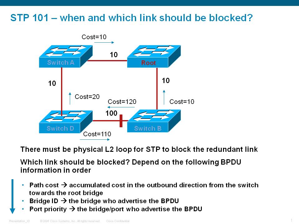
It is generally well understood that in a layer 2 network loops are disastrous. Spanning-Tree Protocol (STP) aids in the detection of loops and breaking that loop to prevent broadcast and unknown unicast packets for circuling around for forever and bringing down the network eventually.
STP operates by selecting a root bridge in the network, who will have all its ports in forwarding and the other switches determining their path cost towards the root switch.
The way the root switch is elected is by means of a priority and when all are equal the lowest switch mac address is selected to be the root. While in default settings a loop is prevented, for good network design it is important that the priorities are set correctly to define where the root switch (and its potential backup) are going to be located.
Root switch election
- The Root Bridge is usually determined by an administratively assigned Priority number
- If all switches have the same Priority, the switch with the lowest MAC address becomes the Root Bridge
- All switch ports begin in the Blocking state to prevent loops
- The Root Bridge, once elected, is the only bridge with all ports active (Forwarding state)
- Root Ports on other switches are placed in Forwarding and provide the lowest cost path back to the Root Bridge
- A port stays in a Blocking state if STP determines that there is another path to the Root Bridge with a lower (better) cost
The states that a port can be in are determined as follows:
- Blocking – Starts in this mode, and stays in Blocking if STA determines that there is a better path to the root bridge. Port only listens for BPDUs from other bridges (Max age 20 seconds)
- Listening – Enters this mode after the Root Bridge election, when BPDU updates are being used to find the lowest cost path to the Root. Attempts to learn other paths to root bridge, to ensure that a loop won’t be created if it begins Forwarding (15 second transition)
- Learning – Enters this mode after Listening. Port adds learned addresses to its table, still not allowed to send data (15 second transition)
- Forwarding – Enters this mode after Listening. Port is now able to send and receive data – Normal operation
Just as a summary overview the follow topology:
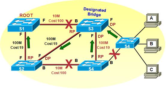
In this example we consider this picture after all BPDU's have been exchanged. Based on priority and mac address S1 is elected as root bridge.
S1 will move both his ports from blocking to forwarding.
Switch S2 will move his root facing port in forwarding mode, which will become the RP (root port).The Port towards S3 will also be in forwarding
because S3, although having a direct link to the root switch S1, the path cost is higher (100) then going via S2->S1 (38). For this reason
the port on S3 to S1 will be blocking.
S4's path to the root bridge is either via S2 or S3. The path to S2 is a higher cost then via S3, ehcne S4->S2 is blocking and the path
to S3 is chosen and that port on S3 will become the RP.
This picture assumes that there are no vlans and just plain ethernet, also this diagram shows a local area network.
What if we want to use multiple vlans or interconnecting this network via a carrier ethernet network to a remote LAN?
Multiple VLANs
In the scenario where you have multiple vlans, regular STP will block the link for all vlans. While this prevents the loop, it is maybe not that
efficient as one node/path is completely in standby mode. It might be nice to forward a few vlans over to switch 1 and the others to switch 2.
Effectively that means that Sw1 is then root for a vlan set and Sw2 for another vlan set.
Regular STP cannot do this, and the logical evolution of htat is MSTP (multiple spanning tree) which is hte more standardized version, and PVST(+) which is a cisco proprietary solution.
They effectively achieve the same PVST and MSTP, one of the key differences is that MSTP sends the bpdu's out untagged on the port, where
PVST sends the bpdu's inline with the vlan, hence are vlan tagged.
Connecting Layer domains via a carrier ethernet network
The most common way to connect 2 separate l2 segments or networks together is via VPLS.
With VPLS the edge nodes from the provider are aggregating the customers L2 traffic, and participate in the L2 spanning tree loop prevention as well as Pseudo Wires over an MPLS core to remote PE's (Provider Edge) to bring the traffic from one segment to the remote site.
The way VPLS works and the interaction with MST or MSTAG and what the differences are will be discussed below.
MST
MST allows us then to run an STP instance per set of vlans that we can configure.
A sample configuration on the ASR9000 PE node looks as follows. Each set of vlans is defined under an instance.
We can adjust the priority per instance if needed, multiple vlans per instance are allowed also.
Sample MST configuration on the ASR9000
spanning-tree mst MYSTP_DOMAIN
name testme
! The name of the MST region is very important, it must be the same for all switches in this region.
! also the definitions of your MST instances need to be the same on all nodes.
revision 1
instance 0
priority 4096
!
instance 1
vlan-ids 100
priority 4096
!
instance 2
vlan-ids 101
priority 4096
!
interface TenGigE0/3/0/6
! Interfaces that are enabled for MST. Note that these are the main interfaces
interface TenGigE0/3/0/7
!
interface Bundle-Ether100
!
interface GigabitEthernet0/0/0/27
!
!
To provide a more graphical example of how MST can be used with 9k's is shown here:
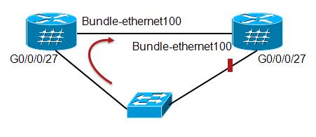
In this case we have a clear STP loop between the 2 9K PE devices interconnceted via a bundle ethernet.
Associated configuration for this example would be as follows:
STP portion
spanning-tree mst Example
name testme
revision 1
instance 0
priority 4096
!
instance 1
vlan-ids 100
priority 4096
!
interface Bundle-Ether100
!
interface GigabitEthernet0/0/0/27
!
With this config we are providing the ability to the 9k PE to send bpdu's out to the other 9k and the access switch.
Also with this config, one link will be blocked and if we elect either 9k to be the root switch (say the one on the left), the link marked RED will be blocked.
This config however doesn't provide for any data configuration forwarding. For this we need to establish a separate bridge-domain whereby we pull in the right EFP's for forwarding the data traffic:
Data Plane portion
interface bundle-e100.100 l2transport
encapsulation dot1q 100
rewrite ingress tag pop 1 symmetric
!rewrite is optional depending on whether all EFP's are in the same vlan.
interface gigabitethernet 0/0/0/27.100 l2transport
encapsulation dot1q 100
rewrite ingress tag pop 1 symmetric
!rewrite is optional depending on whether all EFP's are in the same vlan.
l2vpn
bridge group EXAMPLE
bridge-domain FWD_1
interface g0/0/0/27.100
interface bundle-e100.100
You need to repeat this configuration for every vlan you want to forward. There is another article detailing more about vlan rewrites and the EFP concept in case you're interested. See the related documentation section for a reference.
VPLS
VPLS is the concept of connecting multiple layer 2 domains over an MPLS network for instance. On the ASR9000, a bridge-group is used to pull in the attachment circuits (physical interfaces towards the lan segment) and Pseudo Wires (PW) to the remote PE's.
A sample configuration achieve vpls looks as follows, this provides the configuration for the data plane and assumes there are no loops in your L2 topology either at the customer access site or within your VPLS domain.
To prevent loops in the access network we need to leverage either MSTP, MSTAG or PVSTAG. We'll discuss MSTAG in the next section below.
l2vpn
bridge group VPLS
bridge-domain vpls_1
! the bridge-group vs domain is just a configuration hierarchy, it doesn't serve any special functionality.
interface GigabitEthernet0/0/0/0.100
! Phyiscal interfaces towards a subscriber switch
neighbor 1.1.2.3 pw-id 123
! for H-VPLS we can use PW's also as an attachment circuit
vfi vpls_1_vfi_1
neighbor 5.5.5.5 pw-id 333
! definition of a pseudo wire underneath a Virtual Forwarding Instance
neighbor 6.6.6.6 pw-id 444
!
!
!
!
!
end
The IP address providing in the "neighbor" statement are the MPLS router ID's from the remote PE's. the PW-ID is an arbitrary number, unique, that defines the VC label.
Whether you put the PW's in the VFI or outside the VFI or across VFI's depends on your needs and whether you need SPLIT HORIZON (see below).
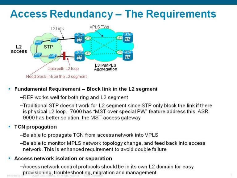
VPLS and L2 Loops
The following picture explains what might happen when we don't use any STP in a VPLS scenario.
In this case there is a loop, but the access switch doesn't know about it because both the 9k PE's, nor the switches
form a closed ring.
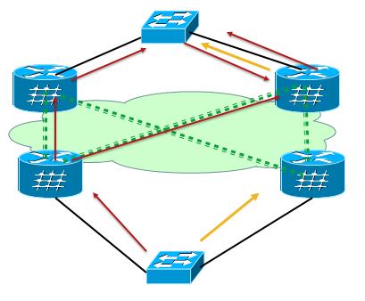
Even if we'd be running MSTP in this scenario there is no loop detected, since by default BPDU's are not forwarded over the pseudo wires.
A potential solution might be to run an L2 link between the 2 southern PE's so that there is a loop on the SOUTH segment and indeed one UP link will be blocked from the access switch to one of the 2 PE's as per regular (M)STP.
The problem is here however that a (broadcast/unknown unicast) packet arriving on the Left South PE's pseudo wire is now then sent to the access switch south AND over the interchassis link (not drawn in this picture) to the SOUTH PE on the right. There will be a loop again.
A proper solution for this model is the use of MST Access gateway which will be highlighted below.
Split Horizon
Normally in a bridge domain, broadcast and unknown unicast from Attachment circuits are replicated to all bridge ports.
Obviously packets are never sent to the AC or PW that the traffic was actually received on.
By default AC's can always forward packets to each other and to (all) Pseudo Wires.
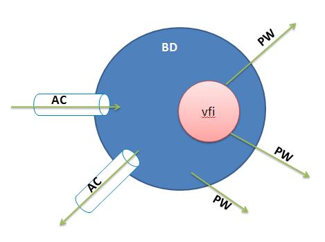
So traffic from the AC "west" will be replicated over all PW's and the South-West AC.
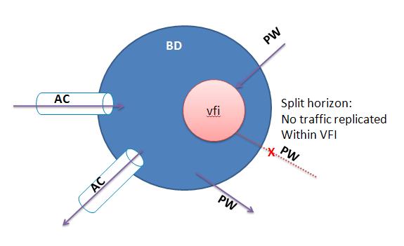
When traffc arrives on a PW then by default packets are never sent out the PW that they are received on and to other Pseudo Wires in the same
VFI. All PW's in the same VFI share the same split horizon group. And traffic is not replicated within the same split horizon group.
When packets arrive on the Pseudo Wire they are NOT forwarded out of PW's in the same VFI.
You can also move Attachment Circuits into a split horizon group to prevent them from speaking with each other by means of the "split horizon" group command underneath the interface which is configured in the l2vpn bridge-domain.
l2vpn
bridge group TEST
bridge-domain SAMPLE
interface g0/1/0/0
split-horizon
interface g0/1/0/10
split horizon
interface te0/2/0/3
vfi VFI_TEST
neighbor 2.2.2.2 pw-id 100
In this case traffic cannot flow between 0/1/0/0 and 0/1/0/10.
MST and Split Horizon
For illustrational purposes consider this sample VPLS design.
In order for MST to work, we need an inter PE attachment circuit to exchange the BPDU's between the two PE nodes drawn in blue.
In this given example the PE_left (PE-1) is considered ROOT.
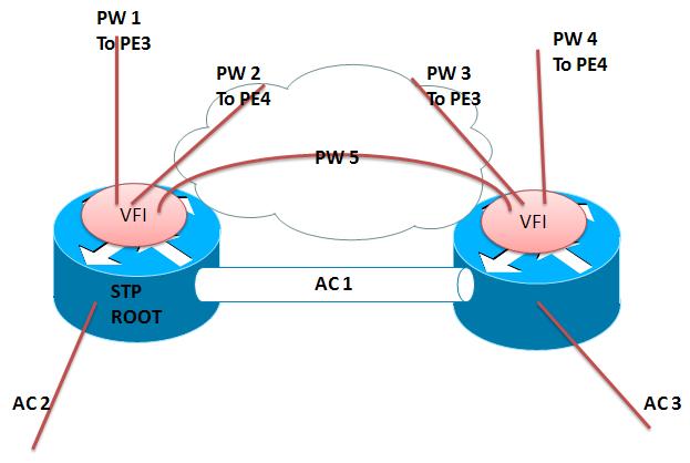
Imagine there is a broadcast coming in on PW-1. Because of split horizon the traffic is not replicated to the PW 2, 3, 4 and 5. But traffic will go down the AC-2 and also sent over to AC-1.
When traffic enters the PE_right (PE-2), it will not go down AC-3 because it is blocking since PE-1 is root, but it will enter the VFI and gets replicated to the PW's in the VFI there so PW 3, 4 and 5. This poses a big problem considering with a replication loop back to PE-3 and also to PE-1.
Omitting PW-5 solves part of the issue so that traffic is not replicated back to PE-1, but it might slow down convergence in case AC-2 is going offline and PE3/4 have not yet updated their mac tables yet.Traffic will still get back to PE-3 and PE-4.
The AC-1 is required for BPDU, and you might want to consider only creating an EFP for hte untagged traffic (BPDU's), but then you might have also forwarding issues in case the PW 1 and 2 are down and you want to send traffic over the AC 1 to PE-right so it can forward the traffic for us to the PE3 and 4.
Wouldn't it be nice if we can live without the AC-1 all together, still run spanning-tree to the CE and have optimum convergence?
Yes. Enter MSTAG.
MSTAG
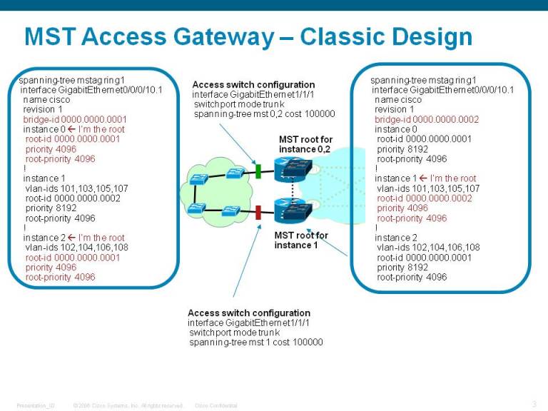
In MSTAG we define the BPDU's on the PE nodes statically presenting them as 1 virtual bridge to the CE.
One link will be blocked, but there is no need for an inter chassis link anymore in this case.
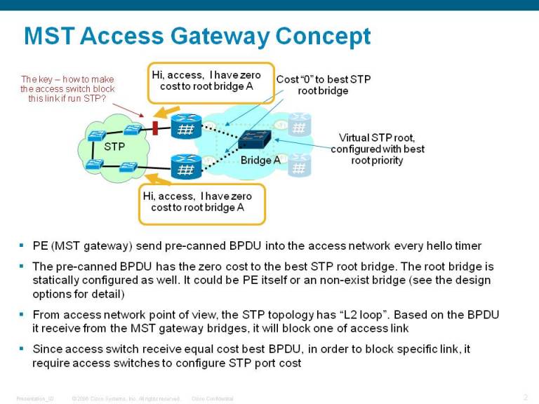
What’s the main function of the MST access gateway?
- Send pre-canned BPDU into access network at hello timer
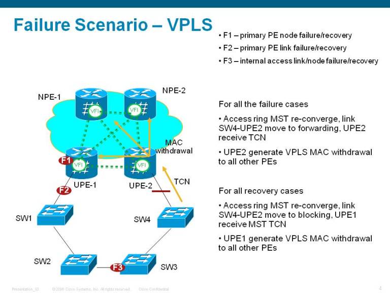
- Snoop the TCN from access network, flush its local MAC address table and trigger VPLS MAC withdrawal accordingly
Major Advantage – scale and local significant
Light MST implementation, for example, it doesn’t keep STP state machine, it doesn’t need to handle received BPDU (except TCN)
The MST is per port scope
Other Advantages
Doesn’t require inter-PE special PW, no single point of failure, no temp L2 loop.
Much robust than the “MST over special PW” solution
Standard based solution, inter-operable with 3rd vendors, work with any network topology
Self protection, even with user mis-configuration, it won’t cause L2 loops
Disadvantages
MST convergence depends on the number of VLANs in the access ring and the MST implementation of the access switches. In any case, don't expect 50msec convergence time
With Cisco 3400 as access switch, the baseline convergence show sub second for link failure, sub 100msec for link recovery, 2-3 seconds for node failure
Note that in this configuration we use the interface with suffix .1 in the MSTAG configuration.
This means we need to define an EFP (Ethernet Flow Point) to capture the BPDU's and TCN packets. In fact, we're not even using the bpdu's received, as we perceive ourselves to be root on the 9k and send these precanned BPDU's out.
We will consume the TCN (topology change notification) and send these into the VPLS network as mac withdrawl messages.
interface gigabitEthernet 0/0/0.10.1 l2transport
encapsulation untagged
Aside from the MST configuration we still need to configure our bridge domains with the EFP's for the data forwarding and our Pseudo Wires to our remote PE's as described above.
MSTP/MSTAG scale for the ASR9000
1) MSTP: There is a single protocol instance which can have the
standard 64 MST Instances (MSTIs) within it. These 64 MSTIs create 64
logical spanning tree topologies within one MSTP region/ domain.
2) MSTAG: You can create a separate protocol instance per physical
interface and each each protocol instance can be in a separate MSTP
region by itself and each one can in turn support 64 MST Instances
(MSTIs) within it.
In general MSTAG is more scalable (multiple regions with 64 MSTIs each)
but can only be used if the ASR9K is in the root (or backup root)
position for every MSTI. MSTP is the normal Cat 6K like version but you
can use all 64 MSTIs without any issues. Both of these can interoperate
with any IEEE standard MSTP implementation so should work with the N7K
VDCs.
Related Information
For more details on regular MST and some IOS interoperability considerations, check this reference:
ASR9000 MST interop with IOS/7600: VLAN pruning
Learn more about vlan rewrites and the concept of EFP's
ASR9000/XR Flexible VLAN matching, EVC, VLAN-Tag rewriting, IRB/BVI and defining L2 services
Xander Thuijs, CCIE #6775
Sr Tech Lead ASR9000
- Mark as Read
- Mark as New
- Bookmark
- Permalink
- Report Inappropriate Content
could you maybe draw a mini topo diagram to show how the cpe is conncted and their vlan stack and where they need to go and what the service needs to achieve?
if the inner vlan is the same for all, but the outer is changing, then yes popping the outer and putting them all in the same BD will allow them to see ecah other.
so if you have EFP-x with dot1q 100 (and inner whatever that is say "q")
and another EFP-y, with a dot1q 200 (and inner also "q").
then popping one tag (the 100 or 200) and if you put EFP-x and y together in the same BD they can communicate together!
cheers!
xander
- Mark as Read
- Mark as New
- Bookmark
- Permalink
- Report Inappropriate Content
Thanks again for your reply. So basically what I'm trying to achieve is QinQ tunnel to act as a last mile carrier grade network so that the SP can tunnel through my network to their client which sits at the end.
ME3600X facing toward the SP which we match with service instances on the vlan tag they send through. Eventually the ME3600X will be replaced with ASR's doing the exact same thing.
Each client shouldn't see one and be able to communicate.
- Mark as Read
- Mark as New
- Bookmark
- Permalink
- Report Inappropriate Content
got it very clear now! thanks for that!
yes your config concept will do the trick.
you match on outer vlan an you switch it through. since you are going between 2 (sub) interfaces, xcon is what you'd want to use here.
you may not want to pop in the tag that we match on, but instead push an extra Q on it (3 vlans now). That will be your Q in your network, then on the remote boundary you pop your Q from it again (leaving 2 original vlans).
if you have an mpls enabled network, instead of using a core facing trunk with all the new "S-TAGs" we are pushing you can also consider building a pw between 2 end points and transport whatever we get in from that EFP over to the other end.
The PW needs to be a type-5 one (transport mode ethernet, not vlan).
cheers
xander
- Mark as Read
- Mark as New
- Bookmark
- Permalink
- Report Inappropriate Content
Hi Xander,
appreciate your help in a couple of questions,
we faced an issue using MC-LAG in a BNG scenario, seems there is a limit of 24 iccp-groups that can be created not more, in MC-LAG we just track the bundle-interface itself for the summary Null route.
1- we want to use MS-TAG, but how can we track an individual vlan/sub-interface in order to inject its summary route to IGP ? using cfm/efd with tracking note end access switch is not cisco any examples ?
2- can we run on the same ASR9000 subscribers on RP mode (bundle-ethernet) and LC mode (sub-interface on physical) at the same time.
thank you,
Regards
Sami
- Mark as Read
- Mark as New
- Bookmark
- Permalink
- Report Inappropriate Content
hi sami,
normally we use one iccp group (one ldp session) between 2 POA's. on that comm channel we can manage multiple bundle interfaces together. there is technically no need to have a session per bundle.
for redundancy, either you'd use mclag OR mstag. using both is "too much" :). with mclag we can use tracking of the interface state, with mstag, the bundle is up, but blocking. so we cant use tracking per-se. and the condition route advertisement is more tricky with mstag, however you can rely on the comm channels and allow forwarding from fwd-state mstag node to blk-state mstag node.
you can have multiple subscriber types together. when using bundle it goes to the rp, when using phy interfaces it goes to the lc.
here a config snippet for route advertisement condition on mclag bundle state.
cheers
xander
- •track access-mclag
- •type line-protocol state
- •interface bundle-ether1
- •subscriber redundancy
- •group 1
- •access-tracking access-mclag
- •router static
- •address-family ipv4 unicast
- •10.0.0.0/24 null0 track access-mclag desc sub-pool-summ
- Mark as Read
- Mark as New
- Bookmark
- Permalink
- Report Inappropriate Content
thanks Xander
so basically we can group some bundles under the same iccp group.
Regards
Sami
- Mark as Read
- Mark as New
- Bookmark
- Permalink
- Report Inappropriate Content
oops forgot to respond to this sami! you are correct, you can manage multiple bundle interfaces under the same iccp group. basically you can use one iccp group per router pair.
cheers
xander
- Mark as Read
- Mark as New
- Bookmark
- Permalink
- Report Inappropriate Content
thanks Xander :)
- Mark as Read
- Mark as New
- Bookmark
- Permalink
- Report Inappropriate Content
Hello Xander,
could you explain a little bit what would be correct configuration for REP-AG in a ring described in lower topology? We have 2 ASR9K on each REP segment end. REP admin VLAN is 96. REP segment is 201 carrying all vlans.
On switch ports connecting to ASR 9k on both ends (0/13 on sw1 and 0/15 on sw3) do we have to configure rep segment 201 command ? Or is it just plain switchport mode trunk ?
Do we have to configure REP edge command on ASR9k ? It is allways mentioned in config guides that we have to enable x/x/x/x.1 encapsulation untagged subinterface. What if admin VLAN is 96 like in our case ? I guess we have to use ".1" anyway.
Does rep instance in spanning-tree repag configuration have to match REP segment 201 ?
And
Here is config of one ASR9K:
spanning-tree repag RING_TEST
preempt delay for 2 seconds
interface GigabitEthernet0/0/0/2.1
instance 201
vlan-ids 1-4094
priority 4096
edge-mode
root-priority 4096
RP/0/RSP0/CPU0:SW-ASR9k-LAB-5# sh run int gigabitEthernet 0/0/0/2.1
Wed Jun 7 14:02:36.160 CET
interface GigabitEthernet0/0/0/2.1 l2transport
encapsulation untagged
!
RP/0/RSP0/CPU0:SW-ASR9k-LAB-5# sh run int gigabitEthernet 0/0/0/1.1
Wed Jun 7 14:02:39.571 CET
interface GigabitEthernet0/0/0/1.1 l2transport
encapsulation untagged
l2vpn
tcn-propagation
bridge group REP_test
bridge-domain RING_TCN
interface GigabitEthernet0/0/0/2.1
interface GigabitEthernet0/0/0/1.1
Thank you
- Mark as Read
- Mark as New
- Bookmark
- Permalink
- Report Inappropriate Content
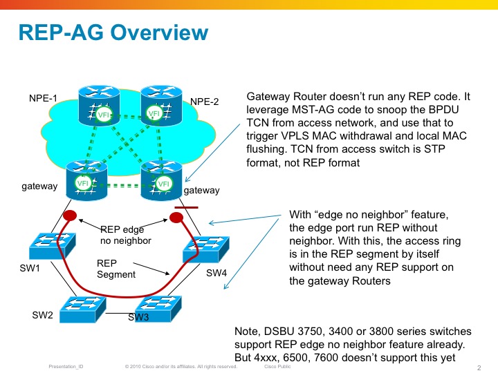
hi tomislav, you'd configure the switch ports to the 9k as if they are connecting to another rep-ring enabled device. the a9k will act as a ring endpoint, so it won't really participate in the ring topology, but merely using the rep messages to convert them into mac flushes etc, same way as with mstag taking the tcn's.
cheers
xander
- Mark as Read
- Mark as New
- Bookmark
- Permalink
- Report Inappropriate Content
Thank you.
I have found on ciscolive BRKSPG-2202, page 89 on pdf document that switch end ports should be configured as "rep edge no-neighbor". This is why I have some doubts. There is no straightforward config documentation for using REP-AG, or at least I couldn't find it.
It really behaves different if you put the port on switch as "edge no neighbor" or not.
Also, could you comment my config related to ".1" subinterface please ? I have configured subif 0/0/0/2.1 toward REP access ring switches, and it is attached to spanning-tree repag configuration (you can see my config in previous mail). On the other hand I have configured interface 0/0/0/1.1 between two ASR routers for propagating TCN's between ASR's. And my question was - this TCN exchange VLAN must be ".1" , right ? Allthough we use REP admin VLAN 96 in REP access ring ?
thank you again, Tom
- Mark as Read
- Mark as New
- Bookmark
- Permalink
- Report Inappropriate Content
sorry I should have been more clear Tom! the port to the a9k should run rep (or effectively propage TCN's), and not be in trunk mode. the right configuration is indeed rep edge no neighbor for that.
here is a few detailed pictures on this more:
xander


- Mark as Read
- Mark as New
- Bookmark
- Permalink
- Report Inappropriate Content
Thank you.
These slides are a little bit more informative.
I tried to enter "rep stcn stp" command but it says :
Command Rejected: For Edge no-neighbor ports, stcn stp is allowed only if spanning-tree mode is mst
So it doesn't work. What if I enter command "rep stcn segment " command instead ? Will ASR recognize those TCN's or are they incompatibile with the code ? I ask because I tried it and when there is some REP ring change (link goes down) for example I don't see any TCN flushes counters increasing :-( ?
"show spanning-tree repag RING_TEST topology-change flushes "
I guess that no TCN's are sent.
Also, if admin VLAN is not default (1) but 96 - does it mean that TCN mesaages are sent via VLAN 96 ?
- Mark as Read
- Mark as New
- Bookmark
- Permalink
- Report Inappropriate Content
Hello Xander,
i'm trying to deploy MSTAG on ASR 9K Pair and i need to work with our current PVST part of the l2 backbone.
my problem is for one vlan, even if i put spanning-tree vlan 1294 priority 61440 on PVST switch, i received on MST switch inconsitent PVST simulation :
%SPANtREE-2-PVSTSIM_FAIL: Blocking designated port Fa0/1: Inconsitent superior PVST BPDU received on VLAN 1294, claiming root 26277:547f.ee9a.b3bc.
Is there someting specific on ASR Side ? it seems that he change priority value and put the value defined on ASR side ( 4096 )
is there a solution in order to have MSTAG configuration and PVST together ?

- Mark as Read
- Mark as New
- Bookmark
- Permalink
- Report Inappropriate Content
Hi Alex,
in case of MSTAG config, why it is recommended by the config guide of MSTAG to set bridge priority of first gateway device higher (0 for example) than the bridge priority of the second gateway device (4096 for example), since the static BPDUs tranfer only the root priority. Practically what is the role of the bridge priority in MSTAG scenario where two access devices are connected to each other and to two gateways (ASRs)?
Thank you in advance
Christos
- « Previous
- Next »
Find answers to your questions by entering keywords or phrases in the Search bar above. New here? Use these resources to familiarize yourself with the community: