- Cisco Community
- Technology and Support
- Security
- Network Security
- IPS 45xx/43xx/42xx appliance and Catalyst 6500 Inline Mode issues
- Subscribe to RSS Feed
- Mark Topic as New
- Mark Topic as Read
- Float this Topic for Current User
- Bookmark
- Subscribe
- Mute
- Printer Friendly Page
IPS 45xx/43xx/42xx appliance and Catalyst 6500 Inline Mode issues
- Mark as New
- Bookmark
- Subscribe
- Mute
- Subscribe to RSS Feed
- Permalink
- Report Inappropriate Content
03-16-2013 09:23 AM - edited 03-10-2019 05:55 AM
Hello to everyone!
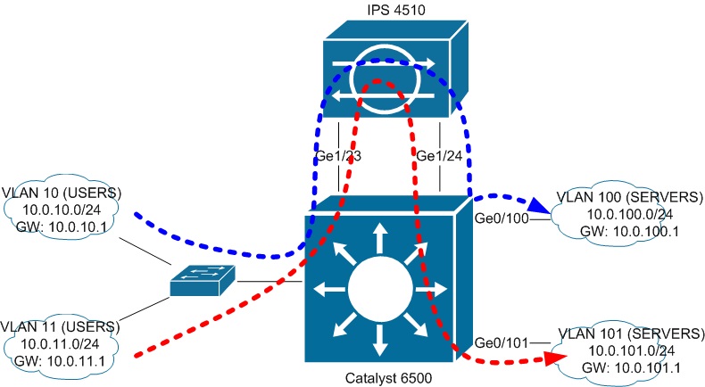
We have recently got our new IPS 4510 appliance and for now there is a task to develop a connection scheme to our backbone multilayer switch (Catalyst 6500).
There are several server's and user's VLANs connected to 6500.
6500 performs inter-vlan routing.
The main task is to "insert" IPS appliance between traffic path from any VLAN to server's VLANs.
The additional task is to provide failover in "fail-open" manner (We have only one 4510 appliance. So if 4510 fails then traffic should continue passing without inspections).
As I understood from this document https://supportforums.cisco.com/docs/DOC-12206 the only way to implement Inline Mode when using multilayer switch is to "take out" default gateway address for inspected subnet on the other VLAN's SVI.
If we replace IDSM-2 with IPS appliance I suppose we can use hardware bypass feature as a failover measure (in case if IPS fails then traffic between bridged VLANs will still be forwarded).
But what if there are several VLANs that should be monitored?
As I understand in such schema we will need to use addtional interface-inline-pair for each monitored VLAN.
But what if we have 20 VLANs for servers and 50 VLANs for users?
Can using of VLAN-group mode handle this problem?
I am not sure but using of VLAN-groups cannot provide bridging between two different VLANs. Am I right?
And will using of VLAN-group make hardware-bypass feature useless?
I tryed to simulate the first scenario in Cisco Packet Tracer (i used a bridge to simulate an IPS appliance in interface-pair inline mode):
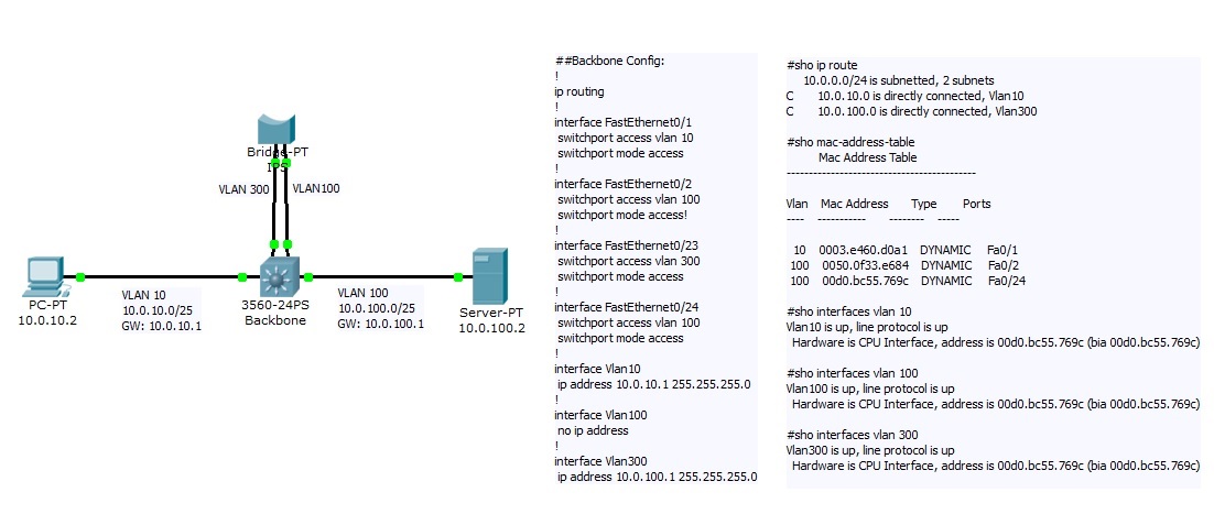
May be this is a bug of Packet Tracer but traffic went through IPS only if it was sent from VLAN 10 to VLAN100.
The return traffic from VLAN 100 to VLAN 10 went through the Catalyst directly.
When Catalyst recieved the frame it said:
"The frame destination MAC address matches the MAC address of the active VLAN interface."
After that it decapsulates the PDU from the Ethernet frame and send IP packet directly to VLAN 10.
Does it mean that there is a need to change SVI's mac address?
Thanks for any advice in advance.
- Labels:
-
IPS and IDS
- Mark as New
- Bookmark
- Subscribe
- Mute
- Subscribe to RSS Feed
- Permalink
- Report Inappropriate Content
03-16-2013 09:35 AM
PS: there is an incorrect #sho mac-address-table output on the second picture.
Here is the correct one:
#sho mac-address-table
Mac Address Table
-------------------------------------------
Vlan Mac Address Type Ports
---- ----------- -------- -----
10 0000.0000.0001 (10.0.10.2) DYNAMIC Fa0/1
100 0000.0000.0002 (10.0.100.2) DYNAMIC Fa0/2
100 00d0.bc55.769c (SVI) DYNAMIC Fa0/24
The other two MACs on the picture are from bridge interfaces.
- Mark as New
- Bookmark
- Subscribe
- Mute
- Subscribe to RSS Feed
- Permalink
- Report Inappropriate Content
03-16-2013 02:14 PM
UPDATE: I have figured out with assymetric data flow in the Packet Tracer.
My mistake was in creating SVI for VLAN 100.
Despite the fact that there was a "no ip address" command entered, it was acting like a router interface.
I suppose this is because of switche's routing logic: If the frame enters in VLAN and this frame has a destination mac of SVI (which is the same by default for all SVIs on a switch) - the switch will forward this frame directly to it's MSFC and it will be routed to the other VLAN without switching.
After deleting this SVI with "no interface vlan 100" command, traffic flow became symmetrical and it began to pass through the bridge in both directions.
I suspect that such behavior will be the same on real multilayer switch.
So be careful when implementing this schema on an existing VLAN. Original SVI should be deleted.
The remaining question is: how to use this approach to redirect several VLANs with one physical interface pair on IPS and keep hardware-bypass feature working?
- Mark as New
- Bookmark
- Subscribe
- Mute
- Subscribe to RSS Feed
- Permalink
- Report Inappropriate Content
03-17-2013 11:05 AM
>> As I understand in such schema we will need to use addtional interface-inline-pair for each monitored VLAN.
Actually you can create a single inline interface pair and create multiple vlan groups within it. Each group can have its own sub-interface number which can be associated with one of the virtual sensors.
So you do not need separate physical interfaces for multiple vlans.
Having said that, have you checked the other inline mode i.e. inline-vlan-pair(a.k.a. on a stick) mode in IPS ?
In this mode, you connect a single physical connection between IPS and the switch & IPS performs inter-vlan routing for each incoming vlan.
To achieve this for the topology figure you've given above, I'd create 2 inline vlan pairs in IPS on a single IPS interface.
First one would bridge Vlan10-Vlan100 and second one would bridge Vlan11-Vlan101.
On the switch side, I'd create a trunk port with all the 4 Vlans 10,11,100 & 101.
This would work for uniquely paired Vlans. Although from what you said:
>> But what if we have 20 VLANs for servers and 50 VLANs for users?
I believe Cisco IPS supports well over 100 such pairs. So it may be able to satisfy your requirement.
However, for this to work, I'm assuming you can break it down to a 1-1 pairing of user and server vlans.
Without 1-1 pairing of vlans, I did not understand how you're achieving this inter-vlan routing even with Cat6K.
For failover-open you can configure IPS bypass mode to auto.
- Mark as New
- Bookmark
- Subscribe
- Mute
- Subscribe to RSS Feed
- Permalink
- Report Inappropriate Content
03-17-2013 02:13 PM
Hello Praveer.
Thank you for response!
About VLAN-pair mode: this is in fact the only mode, where IPS performs changing of VLAN-ID tag.
It is unacceptable for my scenario because this mode is not fault tolerance(hardware-bypass is not supported and useless for this mode).
When I say "IPS failure" I mean complete powering off the IPS appliance.
Also it will decrease the bandwidth twice: 500 Mb/s is not enought for our enviroment even for 1 VLAN (that's the reason why we are replacing our IDSM-2 for IPS 4510).
Interface-pair mode:

As I wrote before this mode is usable when we need to redirect one VLAN. Using of this is possible because IPS is connected to access ports and so it can bridge two different VLANs with a physical connection.
This connection will also remain even if IPS will be powered off (hardware-bypass will still be bridging two vlans).
The complication is to connect several VLANs with the same manner:

I again carefully read the description of VLAN-group mode (I had not the opportunity to get acquainted with this mode "live" because IDSM-2 and AIP-SSM does not support it):
This mode gives an opportunity to forward trunked traffic to IPS. But in this mode there is no changing of the VLAN-ID tag by IPS. I.e. if there is a frame comming to the IPS with VLAN-ID=2 then leaving frame will have the same tag. IPS can only inspect it with a particular virtual sensor based on this tag. Logical interface-pairs are capable only for determining which VLAN should go to which virtual sensor.
If there is an equal VLAN-tags that enters and leaves IPS interfaces - how to use approach with "taking SVI out of inspected VLAN"?
Or may be we should use another mechanism to force traffic flow through IPS: policy-routing, VRF, private-vlan?
May be there is some way to change VLAN-tags as soon as frames are coming to Catalyst port?
May this question is better place in the "Network infrastructure" section?
- Mark as New
- Bookmark
- Subscribe
- Mute
- Subscribe to RSS Feed
- Permalink
- Report Inappropriate Content
03-17-2013 04:00 PM
UPDATE:
I found Cat6k feature: "vlan mapping".
I think it is exactly what I need in my scenario.
But any advices about common principles of "forcing Cat6k to get traffic out itself" are welcome! Especially if your methods were verified
I will post the new schema later.
- Mark as New
- Bookmark
- Subscribe
- Mute
- Subscribe to RSS Feed
- Permalink
- Report Inappropriate Content
03-18-2013 02:43 AM
Here is my guess of how to realise my scenario:

Config on Cat6k should looks something like this:
ip routing
!
interface Ge1/0
switchport trunk encapsulation dot1q
switchport trunk allowed vlan 10-12,110-112
switchport mode trunk
switchport nonegotiate
switchport vlan mapping enable
switchport vlan mapping 110 10
switchport vlan mapping 111 11
switchport vlan mapping 112 12
!
interface Ge1/1
switchport trunk encapsulation dot1q
switchport trunk allowed vlan 10-12
switchport mode trunk
switchport nonegotiate
!
interface vlan 2
ip address 10.0.2.1 255.255.255.0
!
interface vlan 3
ip address 10.0.3.1 255.255.255.0
!
interface Vlan4
ip address 10.0.4.1 255.255.255.0
!
interface Vlan110
ip address 10.0.10.1 255.255.255.0
!
interface Vlan111
ip address 10.0.11.1 255.255.255.0
!
interface Vlan112
ip address 10.0.12.1 255.255.255.0
!
no interface Vlan10
no interface Vlan11
no interface Vlan12
IPS should operate in VLAN-group inline mode. We could separate traffic by VLAN tag to inspect with different virtual sensors or we use one VS for all trunk traffic.
Traffic routed from any VLAN to VLANs 10-12 should go through IPS.
In case if IPS gets powered off - hardware-bypass feature should provide bridging between trunk ports.
In theory it should work.
Remained to test it in practice
Thoughts / suggestions?
Discover and save your favorite ideas. Come back to expert answers, step-by-step guides, recent topics, and more.
New here? Get started with these tips. How to use Community New member guide
