- Cisco Community
- Technology and Support
- Networking
- Networking Knowledge Base
- ELAM Example: Sup2T
- Subscribe to RSS Feed
- Mark as New
- Mark as Read
- Bookmark
- Subscribe
- Printer Friendly Page
- Report Inappropriate Content
- Subscribe to RSS Feed
- Mark as New
- Mark as Read
- Bookmark
- Subscribe
- Printer Friendly Page
- Report Inappropriate Content
09-07-2013 06:48 PM - edited 03-01-2019 04:57 PM
This document provides the steps to perform an ELAM on the Catalyst 6500 Supervisor 2T, explains the most relevant outputs, and how to interpret their results. This example also applies to DFC4 enabled linecards. Please refer to the following document for an overview on ELAM:
Topology
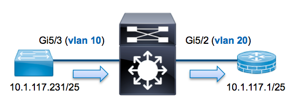 In this example a host on Vlan10 (10.1.117.231) port G5/3 sends an ICMP request to a host on Vlan20 (10.1.117.1) off port G5/2. We will use ELAM to capture this single packet from 10.1.117.231 to 10.1.117.1. It's important to remember that ELAM allows us to capture a single frame.
For Sup2T, each ELAM command will begin with the following syntax: show platform capture elam ...
Determine the ingress FE
We expect the traffic to ingress the switch on port G5/3. Checking the modules in the system we can see that module 5 is the active supervisor. Therefore, we will configure the ELAM on module 5.
Sup2T#show module 5
Mod Ports Card Type Model Serial No.
--- ----- -------------------------------------- ------------------ -----------
5 5 Supervisor Engine 2T 10GE w/ CTS (Acti VS-SUP2T-10G SAL15056BKR
For the Sup2T, we want to perform the ELAM on the L2 forwarding engine (FE) with internal codename Eureka. Note that the L2 FE data bus (DBUS) contains original header information before the L2 and L3 lookup and the result bus (RBUS) contains the results after both L3 and L2 lookups.
Sup2T(config)#service internal
Sup2T# show platform capture elam asic eureka slot 5
Assigned asic_desc=eu50
The service internal command is required to run an ELAM on Sup2T. Note that this configuration simply unlocks the hidden commands.
Configure the Trigger
The Eureka ASIC supports ELAM triggers for IPv4, IPv6, and Other. The ELAM trigger must align to the frame type. If the frame is an IPv4 frame then the trigger must also be IPv4. An IPv4 frame will not be captured with an "other" trigger. The same logic applies to IPv6. The most commonly used triggers based of frame type are provided below.
IPv4IPv6All Frame Types
|
|
|
Most of these fields should be self explanatory. For example, SMAC and DMAC refer to the source MAC address and the destination MAC address, IP_SA and IP_DA refer to the source IPv4 address and the destination IPv4 address, L3_PT refers to the L3 protocol (which can be ICMP, IGMP TCP or UDP).
Note that "other" requires the user to provide the exact hex data and mask for the frame in question and is outside of the scope of this document.
For this example we want to capture the frame based off source and destination IPv4 address. Remember that ELAM triggers allow us to be as specific as needed, so we could additional set fields for TTL, TOS, and L3_PT if needed.
Eureka requires a trigger to be set for DBUS and the RBUS. There are two different packet buffers (PB) in which the RBUS data may reside. Determining the correct PB instance is dependent on the exact module type and ingress port. As a rule of thumb, the recommendation is to configure PB1 and if the RBUS does not trigger repeat with PB2. If no RBUS trigger is provided, IOS will automatically create a trigger for you on PB1.
DBUS Trigger
Sup2T# show platform capture elam trigger master eu50 dbus dbi ingress ipv4 if ip_sa=10.1.117.231 ip_da=10.1.117.1
RBUS Trigger
Sup2T#show platform capture elam trigger slave eu50 rbus rbi pb2
New eu50 slave ELAM is RBI_PB2
Note in this example that we are using eu50 as the ELAM ASIC. This came from the previous step where we selected ASIC Eureka on slot 5 instance zero.
Note also that we selected RBUS PB2 (because internally we know that the RBUS for this particular example will be in PB2). If the incorrect instance was chosen then IOS will provide the following error when attempting to view the ELAM data:
No SOP found or invalid Seq_Num. Pls try other PB interface:
sh pla cap elam tri s eu50 r r pb2
Start the Capture
Now that the ingress FE has been selected and we've configured our trigger, we can start the capture
Sup2T#show platform capture elam start
We can check the status of the ELAM via the status command.
Sup2T#show platform capture elam status
ID# Role ASIC Slot Inst Ver ELAM Status
----- ---- ------- ---- ---- --- --------- ------
eu50 M EUREKA 5 0 1.3 DBI_ING In Progress
eu50 s EUREKA 5 0 1.3 RBI_PB2 In Progress
ID# ELAM Trigger
----- --------- ----------
eu50 DBI_ING FORMAT=IP L3_PROTOCOL=IPV4 IP_SA=10.1.117.231 IP_DA=10.1.117.1
eu50 RBI_PB2 TRIG=1
Once the frame matching the trigger has been received by the FE we will see the ELAM as completed:
Sup2T#show platform capture elam status
ID# Role ASIC Slot Inst Ver ELAM Status
----- ---- ------- ---- ---- --- --------- ------
eu50 M EUREKA 5 0 1.3 DBI_ING Capture Completed
eu50 s EUREKA 5 0 1.3 RBI_PB2 Capture Completed
ID# ELAM Trigger
----- --------- ----------
eu50 DBI_ING FORMAT=IP L3_PROTOCOL=IPV4 IP_SA=10.1.117.231 IP_DA=10.1.117.1
eu50 RBI_PB2 TRIG=1
Interpret the Results
We can display the results via the data command. Below is an excerpt of the ELAM data that is most relevant in this example.
Sup2T#show platform capture elam data
(some output omitted)
DBUS data:
VLAN ............................ [12] = 10
SRC_INDEX ....................... [19] = 0x102
DMAC ............................ = b414.8961.3780
SMAC ............................ = 0025.84e6.8dc1
L3_PROTOCOL ..................... [4] = 0 [IPV4]
L3_PT ........................... [8] = 1 [ICMP]
IP_TTL .......................... [8] = 255
IP_SA ........................... = 10.1.117.231
IP_DA ........................... = 10.1.117.1
RBUS data:
FLOOD ........................... [1] = 0
DEST_INDEX ...................... [19] = 0x101
VLAN ............................ [12] = 20
IP_TTL .......................... [8] = 254
REWRITE_INFO
i0 - replace bytes from ofs 0 to ofs 11 with seq '00 00 0C 07 AC CA B4 14 89 61 37 80'.
From the DBUS data above can validate the frame was received on Vlan10 with a source MAC of 0025.84e6.8dc1 and a destination MAC of b414.8961.3780. We can also see that this is an IPv4 frame sourced from 10.1.117.231 destined to 10.1.117.1. There are several other fields not included in this output such as TOS value, IP flags, IP length, L2 frame length, etc... that are also often useful to check.
We can also validate what port the frame was received on via the SRC_INDEX (the source LTL). For Sup2T, we can map an LTL to a port or group of ports via the following command:
Sup2T#show platform hardware ltl index 0x102
LTL index 0x102 contain ports :
=========================================
Gi5/3
The above output shows that SRC_INDEX of 0x102 maps to port G5/3. This confirms that the frame was received on G5/3.
From the RBUS data we can validate that the frame was routed to Vlan 20 and the TTL was decremented from 255 in the DBUS data to 254. The REWRITE_INFO shows that the FE will replace bytes 0 through 11 (the first 12 bytes) representing the MAC rewrite for the destination and source MAC address. Finally, we can validate from the DEST_INDEX (destination LTL) where this frame was sent
Sup2T#show platform hardware ltl index 0x101
LTL index 0x101 contain ports :
=========================================
Gi5/2
The above output shows that DEST_INDEX of 0x101 maps to port G5/2. This confirms that the frame was sent out G5/2.
Find answers to your questions by entering keywords or phrases in the Search bar above. New here? Use these resources to familiarize yourself with the community: