- Cisco Community
- Technology and Support
- Networking
- Networking Knowledge Base
- How to Form a Catalyst 3850 Data-Stack and Power-Stack
- Subscribe to RSS Feed
- Mark as New
- Mark as Read
- Bookmark
- Subscribe
- Printer Friendly Page
- Report Inappropriate Content
- Subscribe to RSS Feed
- Mark as New
- Mark as Read
- Bookmark
- Subscribe
- Printer Friendly Page
- Report Inappropriate Content
08-05-2015 11:58 AM - edited 03-01-2019 05:06 PM
How to Form a Catalyst 3850 Data-Stack and Power-Stack
Introduction
This document describes the process to properly form a stack-wise and power stack with Cisco Catalyst 3850 switches. It also shows the use of some commands that will help to troubleshoot why a stack is not forming properly.
Requirements
In order to be able to form a switch stack more than 2 switches must be used.
The IOS version used must be the same for all switches. (Software auto upgrade can be configure on a existing stack in order to automatically upgrade newly added switches).
The same mode must be used on all the switches INSTALL or BUNDLE mode.
The right type of cables must be used to achive stack completion. Be aware that cables for the 3750 platform do not work on the 3850 platform.
Components Used
Cisco Catalyst 3850 switches.
Cisco 3850 Stack wise cables.
Cisco 3850 stack power cables.
Network Diagram
The example below, shows how to properly connect a stack of six 3850 switches, together with a power-stack connection example.
Note: The process will be similar for stacks of 2,3,4,5,7,8 and 9 switches.
Each switch has two stack-wise ports(left), let's name the stack wise ports P1 and P2 as shown in the picture.
switch_1 P1 connects to switch_2 P2 (Green cable)
switch_2 P1 connects to switch_3 P2 ( Orange cable)
switch_3 P1 connects to switch_4 P2 (Purple cable)
switch_4 P1 connects to switch_5 P2 (Violet cable)
switch_5 P1 connects to switch_6 P2 (Yellow cable)
switch_6 P1 connects to switch_1 P2 (Brown cable)

Picture 1 Switches in a stack.
Below the steps that show how to cable the stack for power-stack configuration:
StackPower is a feature that allows the power supplies to share the load across multiple devices in a stack. By connecting the switches with power stack cables, the power supplies of up to four stack members can be managed as a one large power supply that provides power to all switches and to the powered devices connected to switch ports.
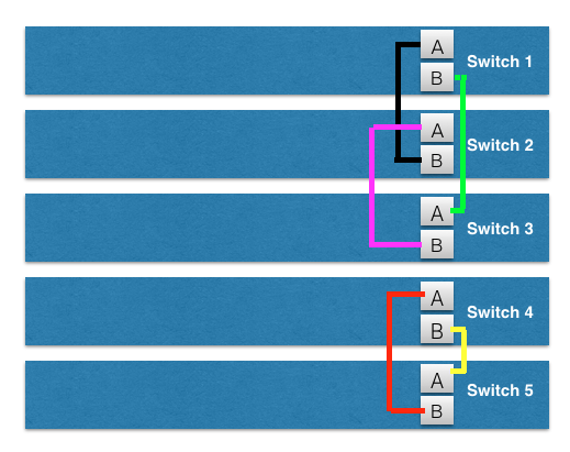
Each switch has two power-stack ports, lets call the ports A and B ( A top, B bottom)
From switch 1 port A we connect to switch 2 port B (pink cable).
From switch 1 port B we connect to switch 4 port A (pale green cable)
From switch 2 port A we connect to switch 3 port B (blue cable)
From switch 3 port A we connect to switch 4 port B (red cable)
From switch 5 port A we connect to switch 6 port B (Red cable).
From switch 6 port A we connect to switch 5 port B (pale blue cable)
Note: Be aware that currently up to four switches can be used on a power-stack configuration and up to nine for a data stack.
Adding a switch to the stack
Note: The switch to be added to the stack must be off. Otherwise, the hole stack will reload.
1.- Add the new switch to the stack by connecting the stack cables to the switch (every cable has a cisco logo on the connector, it must be in the upright position) as shown in the picture below (1):

Picture 2. How to connect the stack-wise cable. (Data cables)
2.- Once the stack-wise cables have been properly connected to the switch, power on the newly added switch either using the power supplies or the power-stack cables.
Verify
After the switch has come up, collect the following :
* show switch
* show switch stack-ports
* sh version
On the show switch output verify that the current state of all switches is READY.
Switch#show switch
Switch/Stack Mac Address : 6400.f125.1b80 - Local Mac Address
Mac persistency wait time: Indefinite
H/W Current
Switch# Role Mac Address Priority Version State
--------------------------------------------------
*1 Active 6400.f125.1b80 15 0 Ready
2 Standby 6400.f155.1dF0 14 0 Ready
On the show switch stack-ports verify that all the ports are shown as OK, that is an indication that the stack-wise cables are working properly:
Switch#show switch stack-ports
Switch # Port 1 Port 2
-------- ------ ------
1 OK OK
2 OK OK
3 OK OK
4 OK OK
5 OK OK
6 OK OK
With the show version command, verify that all the switches on the stack have the same IOS version installed and that all of them have the same mode install or bundle.
Switch Ports Model SW Version SW Image Mode
------ - ------ ------------------------ ----------------------- -------------------------------- ----------
1 56 WS-C3850-48P 03.02.03.SE cat3k_caa-universalk9 INSTALL
2 56 WS-C3850-48P 03.02.03.SE cat3k_caa-universalk9 INSTALL
3 56 WS-C3850-48P 03.02.03.SE cat3k_caa-universalk9 INSTALL
Troubleshoot
The stack might not form properly, this can be due to several reasons. Below there are some of the most common situations showing why a stack does not form propelry.
This can be due to a cable not properly connected or to a faulty stack port on the switch:
Make sure that the cable logo (Cisco logo) is in the upright position on both ends of the cable.
Make sure the cable is plugged in correctly and is not loose.
It can be due to a version mismatch, make sure that all the switches on the stack have the same IOS image.
The auto-upgrade feature can be configured so everytime a switch is added to the stack this will be automatically upgraded to the IOS version used on the stack.
#sh switch
Switch# Role Mac Address Priority Version State
--------------------------------------------------
*1 Active 6400.f125.1480 15 V01 Ready
2 Standby 6400.f125.2680 14 0 V-Mismatch
3 Member 6400.f125.2500 13 0 V-Mismatch
4 Member 6400.f125.2480 12 0 V-Mismatch
It might be due to a license version mismatch, verify that all the switches on the stack have the same license level.
The license level can be verified with the show licence-right-to.use command.
#sh switch
Switch# Role Mac Address Priority Version State
--------------------------------------------------
*1 Active 6400.f125.1480 15 V01 Ready
2 Standby 6400.f125.2680 14 V01 Ready
3 Member 6400.f125.2500 13 V01 Ready
4 Member 6400.f125.2480 12 0 Lic-Mismatch
- Mark as Read
- Mark as New
- Bookmark
- Permalink
- Report Inappropriate Content
Hi , this is very nice post.
Could you please also share how 5 3850 should be connected with respect to stack power ?
I have not found any help so far.
Thanks in advance
- Mark as Read
- Mark as New
- Bookmark
- Permalink
- Report Inappropriate Content
Hello Arjun,
Basically there are two options for power stack:
Option 1
With 5 switches you will have to create two power stacks. One of the guidelines for power stack is as follows:
- A switch power stack can include a maximum of four switches in a ring topology and nine switches in a star topology.
On the picture above, you can see that there are two power stacks (stack1 with 4 switches and stack2 with two switches).
Therefore, in order for you to have 5 switches in a power stack you would have to create one power stack with 3 switches and another power stack with 2 switches.
Option 2
There is another option, called StackPower star configuration that allows to connect up to 9 switches in a power stack. On this configuration there is a master switch that provides the redundancy for all the remaining 8 switches.

Kind Regards.
- Mark as Read
- Mark as New
- Bookmark
- Permalink
- Report Inappropriate Content
Thankyou V much ! Thats a great help.
Can you redirect me a cisco doctment that can be shared with my customer .
Thanks Again
- Mark as Read
- Mark as New
- Bookmark
- Permalink
- Report Inappropriate Content
You are very welcome Arjun,
Please find the link below:
www.cisco.com/c/en/us/td/docs/switches/lan/catalyst3850/hardwar…
Kind Regards.
- Mark as Read
- Mark as New
- Bookmark
- Permalink
- Report Inappropriate Content
Thanks Again . Looks like link has moved .
Also Can you also suggest that 30 CM cable is enough for above 5 Switch stack that you shown or we need longer ones?
- Mark as Read
- Mark as New
- Bookmark
- Permalink
- Report Inappropriate Content
Hi , when you answer above query ,can you please also help if attached is correct way for stackwise cable in a 5 stack switch ? and how about the cable length for stackwise in a 5 stack switch. how much should be minimum required ?
Thanks in advacne

thx in adv
- Mark as Read
- Mark as New
- Bookmark
- Permalink
- Report Inappropriate Content
Hi Arjun,
I have checked this link an it should work:
http://www.cisco.com/c/en/us/td/docs/switches/lan/catalyst3850/hardware/installation/guide/b_c3850_hig/b_c3850_hig_chapter_010.html
Also, the cable length will depend on the configuration you use to stack the switches. If a configuration like the one above is used you can use the 0.5 meter StackWise cable provided with the switches.
If a side by side mounting is used, you may need a longer cable, like the 1 meter cable.
Regarding the connections for the data stack you draw on the picture above. Such connections are right. Just remember, to connect port1 on the switch on top to port2 on the switch below it and so on an so forth.
Kind Regards.
- Mark as Read
- Mark as New
- Bookmark
- Permalink
- Report Inappropriate Content
In this scenario, do the power supplies need to match up as the same or do you just not stack power if the copper switch has a different power supply than the fiber switch?
- Mark as Read
- Mark as New
- Bookmark
- Permalink
- Report Inappropriate Content
Thanks . my all doubts are clear - So i can say
we can use 30 CM "Power stack cable" AND "0.5 M stack wise cable" if go with above method.
I hope I am right :)
Thanks again !
- Mark as Read
- Mark as New
- Bookmark
- Permalink
- Report Inappropriate Content
Hi Brian,
Power supplies of different capacity can be used for a stack power configuration.
Kind Regards.
- Mark as Read
- Mark as New
- Bookmark
- Permalink
- Report Inappropriate Content
Hi Arjun,
You are correct. Basically, the length of the cable will depend on the distance between the switches.
Kind Regards.
- Mark as Read
- Mark as New
- Bookmark
- Permalink
- Report Inappropriate Content
I'm having trouble getting to Power stacks to work with my 6 switches. The data stack works fine, but when I try two power stacks, I can only get one active ring. All others end up as standalone.
Switch#show stack-power
Power Stack Stack Stack Total Rsvd Alloc Unused Num Num
Name Mode Topolgy Pwr(W) Pwr(W) Pwr(W) Pwr(W) SW PS
-------------------- ------ ------- ------ ------ ------ ------ --- ---
Powerstack-1 SP-PS Stndaln 1430 30 1400 0 1 2
Powerstack-11 SP-PS Ring 4290 60 4230 0 3 6
Powerstack-12 SP-PS Stndaln 1430 30 1400 0 1 2
Powerstack-13 SP-PS Stndaln 1430 30 1400 0 1 2
I've tried a 4/2 and a 3/3 split configuration, but I cannot get a second active ring. I'm configuring 3850s, V3.06.05. Any thoughts on how to get past this would be much appreciated.
Thanks
- Mark as Read
- Mark as New
- Bookmark
- Permalink
- Report Inappropriate Content
Hi Geeksturt1,
I was away for holidays and did not have access to email.
Regarding to your question, could you please let me know the following:
I guess you have created power-stack names Powerstack-1,11,12 and 13 correct? Also, have you tried to add the switches to a particular power stack name?
For example:
I am going to create a power stack named power1 for switches 1-4 based on the picture on this article:
Switch# configure terminal
Switch(config)# stack-power stack power1    -- enter power-stack name
Switch(config-stackpower)# mode redundant    -- Power sharing, redundant or strict
Switch(config-stackpower)# end
Now I am going to associate the desired switches to power1 I just created above:
Switch# configure terminal
Switch(config)# stack-power switch 1
Switch(config-switch-stackpower)# stack power1
Switch(config-switch-stackpower)# end
Check that switches have been added to the desired stack-power (power1)
Switch# show stack-power
Power Stack           Stack   Stack    Total   Rsvd    Alloc   Unused  Num  Num
Name                  Mode    Topolgy  Pwr(W)  Pwr(W)  Pwr(W)  Pwr(W)  SW   PS
--------------------  ------  -------  ------  ------  ------  ------  ---  ---
Power1                 SP-PS   Ring     5720    4300   5680    -4260    4    8
Power2                 SP-PS   Ring     2200    1100   2100    -1800    2    4
Now, the same process would have to be used for the other 2 switches.
Kind Regards.
- Mark as Read
- Mark as New
- Bookmark
- Permalink
- Report Inappropriate Content
Why, when you can stack 9 switches into one logic device can't you do the power stacking in more than 4 devices?
also there's a better way to stack so you don't need a long stacking cable. In your example of 6 switches
1-3
3-5
5-6
6-4
4-2
2-1
thanks.
- Mark as Read
- Mark as New
- Bookmark
- Permalink
- Report Inappropriate Content
Luis;
I figure out my problem. Once a stack is improperly configured (say 6 in a stack) some of the power ports shut down and you must run the enable command on those ports before they will become a part of any ring (example: stack-power switch 1 port 1 enable). Thanks for your response.
Find answers to your questions by entering keywords or phrases in the Search bar above. New here? Use these resources to familiarize yourself with the community: