- Cisco Community
- Technology and Support
- Networking
- Networking Knowledge Base
- Configuring the Access Point for the First Time
- Subscribe to RSS Feed
- Mark as New
- Mark as Read
- Bookmark
- Subscribe
- Printer Friendly Page
- Report Inappropriate Content
- Subscribe to RSS Feed
- Mark as New
- Mark as Read
- Bookmark
- Subscribe
- Printer Friendly Page
- Report Inappropriate Content
12-04-2013 04:02 AM - edited 03-01-2019 05:00 PM
This chapter describes how to configure basic settings on the wireless device for the first time. The contents of this chapter are similar to the instructions in the quick start guide that shipped with the wireless device. You can configure all the settings described in this chapter using the CLI, but it might be simplest to browse to the wireless device web-browser interface to complete the initial configuration and then use the CLI to enter additional settings for a more detailed configuration.
This chapter contains these sections:
•![]() Connecting to the 1300 Series Access Point/Bridge Locally
Connecting to the 1300 Series Access Point/Bridge Locally
•![]() Configuring the 802.1X Supplicant
Configuring the 802.1X Supplicant

Note ![]() In this release, the access point radio interfaces are disabled by default.
In this release, the access point radio interfaces are disabled by default.
Before You Start
Before you install the wireless device, make sure you are using a computer connected to the same network as the wireless device, and obtain the following information from your network administrator:
•![]() A system name for the wireless device
A system name for the wireless device
•![]() The case-sensitive wireless service set identifier (SSID) for your radio network
The case-sensitive wireless service set identifier (SSID) for your radio network
•![]() If the wireless device is not on the same subnet as your PC, a default gateway address and subnet mask
If the wireless device is not on the same subnet as your PC, a default gateway address and subnet mask
•![]() A Simple Network Management Protocol (SNMP) community name and the SNMP file attribute (if SNMP is in use)
A Simple Network Management Protocol (SNMP) community name and the SNMP file attribute (if SNMP is in use)
Resetting the Device to Default Settings
If you need to start over during the initial setup process, you can reset the access point to factory default settings.Resetting to Default Settings Using the MODE Button
Resetting to Default Settings Using the GUI
Resetting to Default Settings Using the CLI

If you want to reset the access point to its default settings and a static IP address, use the write erase or erase /all nvram command. If you want to erase everything including the static IP address, in addition to the above commands, use the erase and erase boot static-ipaddr static-ipmask command.
From the privileged EXEC mode, you can reset the access point/bridge configuration to factory default values using the CLI by following these steps:
Step 1 ![]() Enter erase nvram: to erase all NVRAM files including the startup configuration.
Enter erase nvram: to erase all NVRAM files including the startup configuration.
Note ![]() The erase nvram command does not erase a static IP address.
The erase nvram command does not erase a static IP address.
Step 2 ![]() Follow the step below to erase a static IP address and subnet mask. Otherwise, go to step 3.
Follow the step below to erase a static IP address and subnet mask. Otherwise, go to step 3.
a. ![]() Enter write default-config.
Enter write default-config.
Step 3 ![]() Enter Y when the following CLI message displays: Erasing the nvram filesystem will remove all configuration files! Continue? [confirm].
Enter Y when the following CLI message displays: Erasing the nvram filesystem will remove all configuration files! Continue? [confirm].
Step 4 ![]() Enter reload when the following CLI message displays: Erase of nvram: complete. This command reloads the operating system.
Enter reload when the following CLI message displays: Erase of nvram: complete. This command reloads the operating system.
Step 5 ![]() Enter Y when the following CLI message displays: Proceed with reload? [confirm].
Enter Y when the following CLI message displays: Proceed with reload? [confirm].
Step 6 ![]() After the access point/bridge reboots, you can reconfigure the access point by using the Web-browser interface if you previously assigned a static IP address, or the CLI if you did not.
After the access point/bridge reboots, you can reconfigure the access point by using the Web-browser interface if you previously assigned a static IP address, or the CLI if you did not.
The access point is configured with the factory default values including the IP address (set to receive an IP address using DHCP). To obtain the access point/bridge's new IP address, you can use the show interface bvi1 CLI command.
The 1300 series access point/bridge assumes a radio network role of a root access point. To configure it as a bridge, you must manually place it in install mode in order to align the antennas and establish a link. To establish the link you must have two access point/bridges configured in the install mode. In the install mode, one access point/bridge must be configured as a root bridge and the other a non-root bridge. To facilitate the configuration, an automatic option is available when the access point/bridge is in the install mode. After the wireless link is established and the bridge antennas are aligned, you take both access point/bridges out of install mode and place them on your LAN as root and non-root bridges.
Note ![]() "Resetting the Device to Default Settings" sectionIf xon/xoff flow control does not work, use no flow control.
"Resetting the Device to Default Settings" sectionIf xon/xoff flow control does not work, use no flow control.
Step 7 ![]() When connected, press enter or type en to access the command prompt. Pressing enter takes you to the user exec mode. entering en prompts you for a password, then takes you to the privileged exec mode. The default password is Cisco and is case-sensitive.
When connected, press enter or type en to access the command prompt. Pressing enter takes you to the user exec mode. entering en prompts you for a password, then takes you to the privileged exec mode. The default password is Cisco and is case-sensitive.
Note ![]() If xon/xoff flow control does not work, use no flow control.
If xon/xoff flow control does not work, use no flow control.
Step 8 ![]() When connected, press enter or type en to access the command prompt. Pressing enter takes you to the user exec mode. Entering en prompts you for a password, then takes you to the privileged exec mode. The default password is Cisco and is case-sensitive.
When connected, press enter or type en to access the command prompt. Pressing enter takes you to the user exec mode. Entering en prompts you for a password, then takes you to the privileged exec mode. The default password is Cisco and is case-sensitive.
Note ![]() When your configuration changes are completed, you must remove the serial cable from the access point.
When your configuration changes are completed, you must remove the serial cable from the access point.
Connecting to the 1300 Series Access Point/Bridge Locally
If you need to configure the access point/bridge locally (without connecting the access point/bridge to a wired LAN), you can connect a PC to the Ethernet port on the long-reach power injector using a Category 5 Ethernet cable. You can use a local connection to the power injector's Ethernet port much as you would use a serial port connection.
Note ![]() You do not need a special crossover cable to connect your PC to the power injector; you can use either a straight-through cable or a crossover cable.
You do not need a special crossover cable to connect your PC to the power injector; you can use either a straight-through cable or a crossover cable.
Follow these steps to connect to the bridge locally:
Step 1 ![]() Make sure that the PC you intend to use is configured to obtain an IP address automatically, or manually assign it an IP address within the same subnet as the access point/bridge IP address. For example, if you assigned the access point/bridge an IP address of 10.0.0.1, assign the PC an IP address of 10.0.0.20.
Make sure that the PC you intend to use is configured to obtain an IP address automatically, or manually assign it an IP address within the same subnet as the access point/bridge IP address. For example, if you assigned the access point/bridge an IP address of 10.0.0.1, assign the PC an IP address of 10.0.0.20.
Step 2 ![]() With the power cable disconnected from the power injector, connect your PC to the power injector using a Category 5 Ethernet cable. You can use either a crossover cable or a straight-through cable.
With the power cable disconnected from the power injector, connect your PC to the power injector using a Category 5 Ethernet cable. You can use either a crossover cable or a straight-through cable.
Note ![]() Communication takes place between the power injector and the access point/bridge using Ethernet Port 0. Do not attempt to change any of the Ethernet Port 0 settings.
Communication takes place between the power injector and the access point/bridge using Ethernet Port 0. Do not attempt to change any of the Ethernet Port 0 settings.
Step 3 ![]() Connect the power injector to the access point/bridge using dual coaxial cables.
Connect the power injector to the access point/bridge using dual coaxial cables.
Step 4 ![]() Connect the power injector power cable and power up the access point/bridge.
Connect the power injector power cable and power up the access point/bridge.
Step 5 ![]() Follow the steps in the "Assigning Basic Settings" section. If you make a mistake and need to start over, follow the steps in the "Resetting the Device to Default Settings" procedure.
Follow the steps in the "Assigning Basic Settings" section. If you make a mistake and need to start over, follow the steps in the "Resetting the Device to Default Settings" procedure.
Step 6 ![]() After configuring the access point/bridge, remove the Ethernet cable from your PC and connect the power injector to your wired LAN.
After configuring the access point/bridge, remove the Ethernet cable from your PC and connect the power injector to your wired LAN.
Note ![]() When you connect your PC to the access point/bridge or reconnect your PC to the wired LAN, you might need to release and renew the IP address on the PC. On most PCs, you can perform a release and renew by rebooting your PC or by entering ipconfig /release and ipconfig /renew commands in a command prompt window. Consult your PC operating instructions for detailed instructions.
When you connect your PC to the access point/bridge or reconnect your PC to the wired LAN, you might need to release and renew the IP address on the PC. On most PCs, you can perform a release and renew by rebooting your PC or by entering ipconfig /release and ipconfig /renew commands in a command prompt window. Consult your PC operating instructions for detailed instructions.
Default Radio Settings
Beginning with Cisco IOS Release 12.3(8)JA, access point radios are disabled and no default SSID is assigned. This was done in order to prevent unauthorized users to access a customer's wireless network through an access point having a default SSID and no security settings. You must create an SSID before you can enable the access point radio interfaces.
See Chapter 6 "Configuring Radio Settings" for additional information.
Assigning Basic Settings
After you determine or assign the wireless device IP address, you can browse to the wireless device Express Setup page and perform an initial configuration:
Step 1 ![]() Open your Internet browser. The wireless device web-browser interface is compatible with Microsoft Internet Explorer version 6.0, and with Netscape version 7.0.
Open your Internet browser. The wireless device web-browser interface is compatible with Microsoft Internet Explorer version 6.0, and with Netscape version 7.0.
Step 2 ![]() Enter the wireless device IP address in the browser address line and press Enter. An Enter Network Password screen appears.
Enter the wireless device IP address in the browser address line and press Enter. An Enter Network Password screen appears.
Step 3 ![]() Press Tab to bypass the Username field and advance to the Password field.
Press Tab to bypass the Username field and advance to the Password field.
Step 4 ![]() Enter the case-sensitive password Cisco and press Enter. Your page may differ depending on the access point model you are using. The Express Setup screen appears. Figure 4-1 and Figure 4-2 shows the Express Setup page for the 1100 series access points. Your pages may differ depending on the access point model you are using.
Enter the case-sensitive password Cisco and press Enter. Your page may differ depending on the access point model you are using. The Express Setup screen appears. Figure 4-1 and Figure 4-2 shows the Express Setup page for the 1100 series access points. Your pages may differ depending on the access point model you are using.
Figure 4-1 Express Setup Page for 1100 Series Access Points
Figure 4-2 Express Setup Page for 1130, 1200, and 1240 Series Access Points
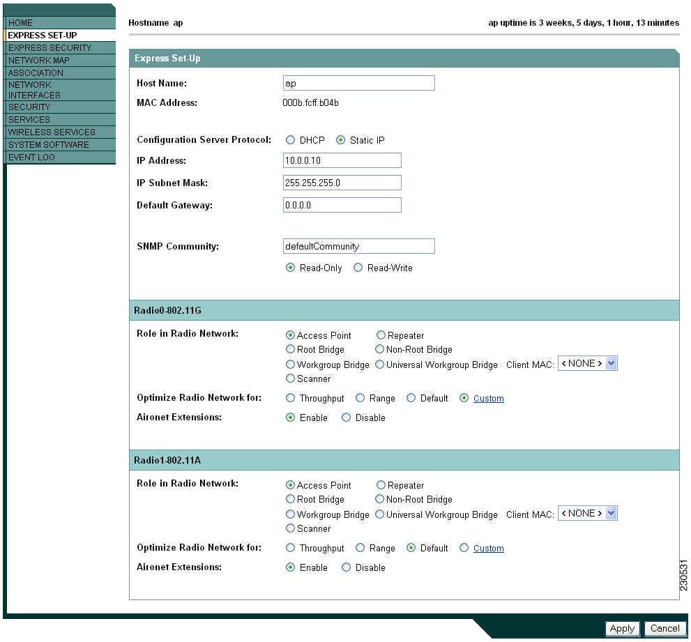
Note ![]() Figure 4-2 shows the Express Setup page for an 1130 series access point. The 1200 series is similar, but does not support the universal workgroup bridge role.
Figure 4-2 shows the Express Setup page for an 1130 series access point. The 1200 series is similar, but does not support the universal workgroup bridge role.
Figure 4-3 Express Setup Page for the 1250 Series Access Point
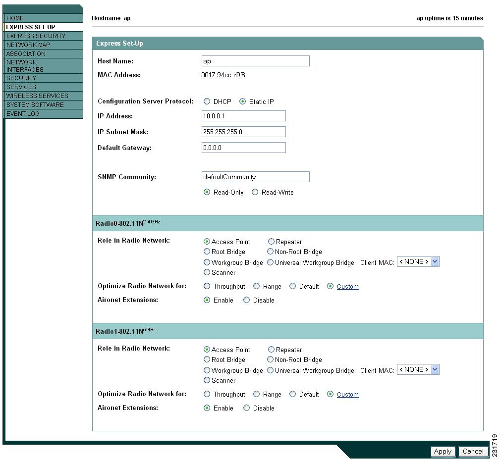
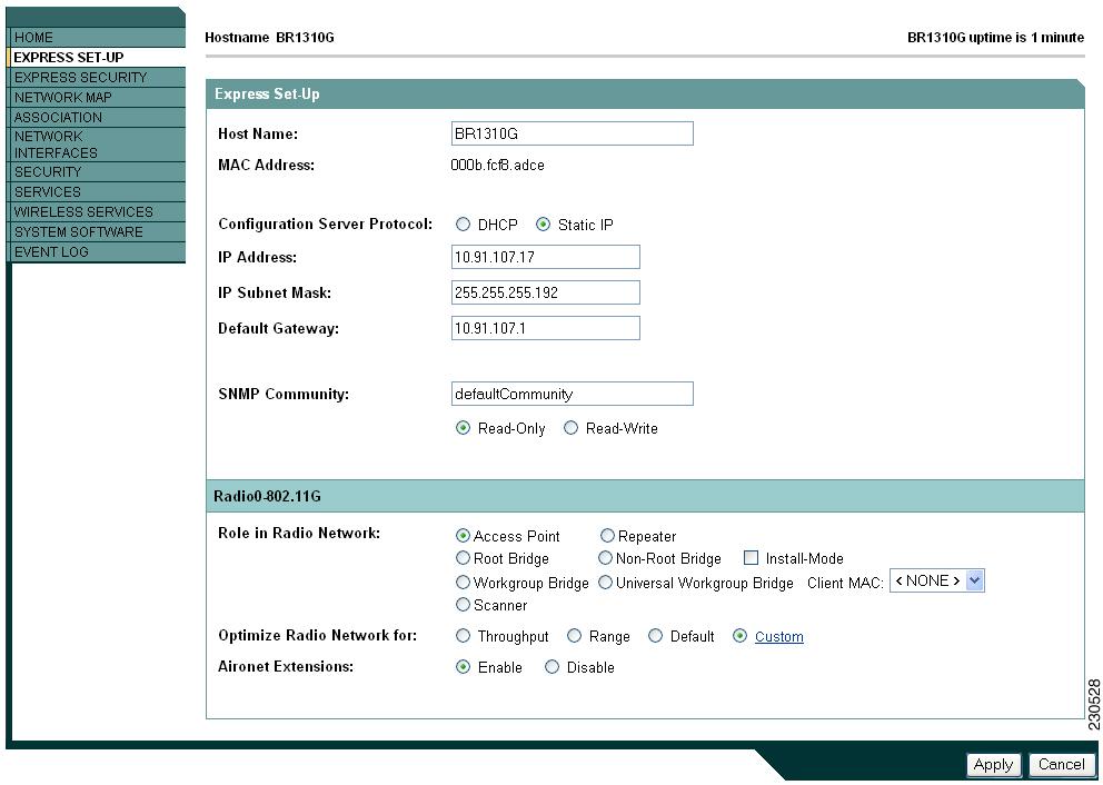
Figure 4-4 Express Setup Page for the 1300 Series Access Point/Bridge
Step 5 ![]() Enter the configuration settings you obtained from your system administrator. The configurable settings include:
Enter the configuration settings you obtained from your system administrator. The configurable settings include:
•![]()
–![]() Repeater—A non-root device; accepts associations from clients and bridges wireless traffic from the clients to root access point connected to the wireless LAN. This setting can be applied to any access point.
Repeater—A non-root device; accepts associations from clients and bridges wireless traffic from the clients to root access point connected to the wireless LAN. This setting can be applied to any access point.
–![]() Root Bridge—Establishes a link with a non-root bridge. In this mode, the device also accepts associations from clients. This setting is available only for the 1200 and 1240 series access points.
Root Bridge—Establishes a link with a non-root bridge. In this mode, the device also accepts associations from clients. This setting is available only for the 1200 and 1240 series access points.
–![]() Non-Root Bridge—In this mode, the device establishes a link with a root bridge. This setting is available only for the 1200 and 1240 series access points.
Non-Root Bridge—In this mode, the device establishes a link with a root bridge. This setting is available only for the 1200 and 1240 series access points.
–![]() Install Mode—Places the 1300 series access point/bridge in auto installation mode so you can align and adjust a bridge link for optimum efficiency.
Install Mode—Places the 1300 series access point/bridge in auto installation mode so you can align and adjust a bridge link for optimum efficiency.
–![]() Workgroup Bridge—Emulates a Cisco Aironet 350 Series Workgroup Bridge. In the Workgroup bridge mode, the access point functions as a client device that associates with a Cisco Aironet access point or bridge. A wokgroup bridge can have a maximum of 254 clients, presuming that no other wireless clients are associated to the root bridge or access point. This setting is available for the 1100, 1200, and 1300 series access points.
Workgroup Bridge—Emulates a Cisco Aironet 350 Series Workgroup Bridge. In the Workgroup bridge mode, the access point functions as a client device that associates with a Cisco Aironet access point or bridge. A wokgroup bridge can have a maximum of 254 clients, presuming that no other wireless clients are associated to the root bridge or access point. This setting is available for the 1100, 1200, and 1300 series access points.
–![]() Universal Workgroup Bridge—Configures the access point as a workgroup bridge capable of associating with non-Cisco access points. This setting is available on 1130, and 1240 series access points and 1300 series access point/bridges.
Universal Workgroup Bridge—Configures the access point as a workgroup bridge capable of associating with non-Cisco access points. This setting is available on 1130, and 1240 series access points and 1300 series access point/bridges.
–![]() Client MAC:—The Ethernet MAC address of the client connected to the universal workgroup bridge.
Client MAC:—The Ethernet MAC address of the client connected to the universal workgroup bridge.
–![]() Scanner—Functions as a network monitoring device. In the Scanner mode, the access point does not accept associations from clients. It continuously scans and reports wireless traffic it detects from other wireless devices on the wireless LAN. All access points can be configured as a scanner.
Scanner—Functions as a network monitoring device. In the Scanner mode, the access point does not accept associations from clients. It continuously scans and reports wireless traffic it detects from other wireless devices on the wireless LAN. All access points can be configured as a scanner.
•![]() Optimize Radio Network for—Use this setting to select either preconfigured settings for the wireless device radio or customized settings for the wireless device radio.
Optimize Radio Network for—Use this setting to select either preconfigured settings for the wireless device radio or customized settings for the wireless device radio.
–![]() Throughput—Maximizes the data volume handled by the wireless device, but might reduce its range.
Throughput—Maximizes the data volume handled by the wireless device, but might reduce its range.
–![]() Range—Maximizes the wireless device range but might reduce throughput.
Range—Maximizes the wireless device range but might reduce throughput.
–![]() Default—Sets the default values for the access point.
Default—Sets the default values for the access point.
–![]() Custom—The wireless device uses the settings you enter on the Network Interfaces. Clicking Custom takes you to the Network Interfaces:
Custom—The wireless device uses the settings you enter on the Network Interfaces. Clicking Custom takes you to the Network Interfaces:
Radio-802.11b Settings page.
Radio-802.11b Settings page.
Radio-802.11n Settings page (1250).
Radio-802.11n Settings page (1250)
•![]() Aironet Extensions—Enable this setting if there are only Cisco devices on your wireless LAN.
Aironet Extensions—Enable this setting if there are only Cisco devices on your wireless LAN.
Step 6 ![]() Click Apply to save your settings.
Click Apply to save your settings.
Step 7 ![]() Click Network Interfaces to browse to the Network Interfaces Summary page.
Click Network Interfaces to browse to the Network Interfaces Summary page.
Step 8 ![]() Click the radio interface to browse to the Network Interfaces: Radio Status page.
Click the radio interface to browse to the Network Interfaces: Radio Status page.
Step 9 ![]() Click the Settings tab to browse to the Settings page for the radio interface.
Click the Settings tab to browse to the Settings page for the radio interface.
Step 10 ![]() Click Enable to enable the radio.
Click Enable to enable the radio.
Step 11 ![]() Click Apply.
Click Apply.
Your wireless device is now running but probably requires additional configuring to conform to your network operational and security requirements. Consult the chapters in this manual for the information you need to complete the configuration.
Default Settings on the Express Setup Page
Table 4-1 lists the default settings for the settings on the Express Setup page.
Setting | Default |
|---|---|
Host Name | ap |
Optimize Radio Network for | Throughput |
Aironet Extensions | Enable |
Configuring Basic Security Settings
After you assign basic settings to the wireless device, you must configure security settings to prevent unauthorized access to your network. Because it is a radio device, the wireless device can communicate beyond the physical boundaries of your worksite.
Just as you use the Express Setup page to assign basic settings, you can use the Express Security page to create unique SSIDs and assign one of four security types to them. Figure 4-5 shows a typical Express Security page.
Figure 4-5 Express Security Page
The Express Security page helps you configure basic security settings. You can use the web-browser interface main Security pages to configure more advanced security settings.
Understanding Express Security Settings
SSIDs that you create appear in the SSID table at the bottom of the page. You can create up to 16 SSIDs on the wireless device. On dual-radio wireless devices, the SSIDs that you create are enabled on both radio interfaces.
Note ![]() In Cisco IOS Release 12.4(10b)JA and 12.3(8)JEC, there is no default SSID. You must configure an SSID before client devices can associate to the access point.
In Cisco IOS Release 12.4(10b)JA and 12.3(8)JEC, there is no default SSID. You must configure an SSID before client devices can associate to the access point.
The SSID can consist of up to 32 alphanumeric, case-sensitive, characters.
The first character can not contain the following characters:
•![]() Exclamation point
Exclamation point
•![]() Pound sign (#)
Pound sign (#)
•![]() Semicolon (;)
Semicolon (;)
The following characters are invalid and cannot be used in an SSID:
•![]() Plus sign
Plus sign
•![]() Right bracket (])
Right bracket (])
•![]() Front slash (/)
Front slash (/)
•![]() Quotation mark (")
Quotation mark (")
•![]() Tab
Tab
•![]() Trailing spaces
Trailing spaces
Using VLANs
If you use VLANs on your wireless LAN and assign SSIDs to VLANs, you can create multiple SSIDs using any of the four security settings on the Express Security page. However, if you do not use VLANs on your wireless LAN, the security options that you can assign to SSIDs are limited because on the Express Security page encryption settings and authentication types are linked. Without VLANs, encryption settings (WEP and ciphers) apply to an interface, such as the 2.4-GHz radio, and you cannot use more than one encryption setting on an interface. For example, when you create an SSID with static WEP with VLANs disabled, you cannot create additional SSIDs with WPA authentication because they use different encryption settings. If you find that the security setting for an SSID conflicts with another SSID, you can delete one or more SSIDs to eliminate the conflict.
Express Security Types
Table 4-2 describes the four security types that you can assign to an SSID.
Express Security Limitations
Because the Express Security page is designed for simple configuration of basic security, the options available are a subset of the wireless device security capabilities. Keep these limitations in mind when using the Express Security page:
•![]() If the No VLAN option is selected, the static WEP key can be configured once. If you select Enable VLAN, the static WEP key should be disabled.
If the No VLAN option is selected, the static WEP key can be configured once. If you select Enable VLAN, the static WEP key should be disabled.
•![]() You cannot edit SSIDs. However, you can delete SSIDs and re-create them.
You cannot edit SSIDs. However, you can delete SSIDs and re-create them.
•![]() You cannot assign SSIDs to specific radio interfaces. The SSIDs that you create are enabled on all radio interfaces. To assign SSIDs to specific radio interfaces, use the Security SSID Manager page.
You cannot assign SSIDs to specific radio interfaces. The SSIDs that you create are enabled on all radio interfaces. To assign SSIDs to specific radio interfaces, use the Security SSID Manager page.
•![]() You cannot configure multiple authentication servers. To configure multiple authentication servers, use the Security Server Manager page.
You cannot configure multiple authentication servers. To configure multiple authentication servers, use the Security Server Manager page.
•![]() You cannot configure multiple WEP keys. To configure multiple WEP keys, use the Security Encryption Manager page.
You cannot configure multiple WEP keys. To configure multiple WEP keys, use the Security Encryption Manager page.
•![]() You cannot assign an SSID to a VLAN that is already configured on the wireless device. To assign an SSID to an existing VLAN, use the Security SSID Manager page.
You cannot assign an SSID to a VLAN that is already configured on the wireless device. To assign an SSID to an existing VLAN, use the Security SSID Manager page.
•![]() You cannot configure combinations of authentication types on the same SSID (for example, MAC address authentication and EAP authentication). To configure combinations of authentication types, use the Security SSID Manager page.
You cannot configure combinations of authentication types on the same SSID (for example, MAC address authentication and EAP authentication). To configure combinations of authentication types, use the Security SSID Manager page.
Using the Express Security Page
Follow these steps to create an SSID using the Express Security page:
Step 1 ![]() Type the SSID in the SSID entry field. The SSID can contain up to 32 alphanumeric characters.
Type the SSID in the SSID entry field. The SSID can contain up to 32 alphanumeric characters.
Step 2 ![]() To broadcast the SSID in the wireless device beacon, check the Broadcast SSID in Beacon check box. When you broadcast the SSID, devices that do not specify an SSID can associate to the wireless device. This is a useful option for an SSID used by guests or by client devices in a public space. If you do not broadcast the SSID, client devices cannot associate to the wireless device unless their SSID matches this SSID. Only one SSID can be included in the wireless device beacon.
To broadcast the SSID in the wireless device beacon, check the Broadcast SSID in Beacon check box. When you broadcast the SSID, devices that do not specify an SSID can associate to the wireless device. This is a useful option for an SSID used by guests or by client devices in a public space. If you do not broadcast the SSID, client devices cannot associate to the wireless device unless their SSID matches this SSID. Only one SSID can be included in the wireless device beacon.
Step 3 ![]() (Optional) Check the Enable VLAN ID check box and enter a VLAN number (1 through 4095) to assign the SSID to a VLAN. You cannot assign an SSID to an existing VLAN.
(Optional) Check the Enable VLAN ID check box and enter a VLAN number (1 through 4095) to assign the SSID to a VLAN. You cannot assign an SSID to an existing VLAN.
Step 4 ![]() (Optional) Check the Native VLAN check box to mark the VLAN as the native VLAN.
(Optional) Check the Native VLAN check box to mark the VLAN as the native VLAN.
Step 5 ![]() Select the security setting for the SSID. The settings are listed in order of robustness, from No Security to WPA, which is the most secure setting. If you select EAP Authentication or WPA, enter the IP address and shared secret for the authentication server on your network.
Select the security setting for the SSID. The settings are listed in order of robustness, from No Security to WPA, which is the most secure setting. If you select EAP Authentication or WPA, enter the IP address and shared secret for the authentication server on your network.
Note ![]() If you do not use VLANs on your wireless LAN, the security options that you can assign to multiple SSIDs are limited. See the "Using VLANs" section for details.
If you do not use VLANs on your wireless LAN, the security options that you can assign to multiple SSIDs are limited. See the "Using VLANs" section for details.
Step 6 ![]() Click Apply. The SSID appears in the SSID table at the bottom of the page.
Click Apply. The SSID appears in the SSID table at the bottom of the page.
CLI Configuration Examples
The examples in this section show the CLI commands that are equivalent to creating SSIDs using each security type on the Express Security page. This section contains these example configurations:
Example: No Security
This example shows part of the configuration that results from using the Express Security page to create an SSID called no_security_ssid, including the SSID in the beacon, assigning it to VLAN 10, and selecting VLAN 10 as the native VLAN:
!
dot11 ssid no_security_ssid
authentication open
vlan 10
!
interface Dot11Radio0.10
encapsulation dot1Q 10 native
no ip route-cache
bridge-group 1
bridge-group 1 subscriber-loop-control
bridge-group 1 block-unknown-source
no bridge-group 1 source-learning
no bridge-group 1 unicast-flooding
bridge-group 1 spanning-disabled
!
interface Dot11Radio1
no ip address
no ip route-cache
!
ssid no_security_ssid
!
speed basic-6.0 9.0 basic-12.0 18.0 basic-24.0 36.0 48.0 54.0
rts threshold 2312
station-role root
!
interface Dot11Radio1.10
encapsulation dot1Q 10 native
no ip route-cache
bridge-group 1
bridge-group 1 subscriber-loop-control
bridge-group 1 block-unknown-source
no bridge-group 1 source-learning
no bridge-group 1 unicast-flooding
bridge-group 1 spanning-disabled
Example: Static WEP
This example shows part of the configuration that results from using the Express Security page to create an SSID called static_wep_ssid, excluding the SSID from the beacon, assigning the SSID to VLAN 20, selecting 3 as the key slot, and entering a 128-bit key:
ssid static_wep_ssid
vlan 20
authentication open
!
interface Dot11Radio0
no ip address
no ip route-cache
!
encryption vlan 20 key 3 size 128bit 7 FFD518A21653687A4251AEE1230C transmit-key
encryption vlan 20 mode wep mandatory
!
speed basic-1.0 basic-2.0 basic-5.5 basic-11.0
rts threshold 2312
station-role root
bridge-group 1
bridge-group 1 subscriber-loop-control
bridge-group 1 block-unknown-source
no bridge-group 1 source-learning
no bridge-group 1 unicast-flooding
bridge-group 1 spanning-disabled
ssid statuc_wep_ssid
!
interface Dot11Radio0.20
encapsulation dot1Q 20
no ip route-cache
bridge-group 20
bridge-group 20 subscriber-loop-control
bridge-group 20 block-unknown-source
no bridge-group 20 source-learning
no bridge-group 20 unicast-flooding
bridge-group 20 spanning-disabled
!
interface Dot11Radio1
no ip address
no ip route-cache
!
encryption vlan 20 key 3 size 128bit 7 741F07447BA1D4382450CB68F37A transmit-key
encryption vlan 20 mode wep mandatory
!
ssid static_wep_ssid
!
speed basic-6.0 9.0 basic-12.0 18.0 basic-24.0 36.0 48.0 54.0
rts threshold 2312
station-role root
bridge-group 1
bridge-group 1 subscriber-loop-control
bridge-group 1 block-unknown-source
no bridge-group 1 source-learning
no bridge-group 1 unicast-flooding
bridge-group 1 spanning-disabled
!
interface Dot11Radio1.20
encapsulation dot1Q 20
no ip route-cache
bridge-group 20
bridge-group 20 subscriber-loop-control
bridge-group 20 block-unknown-source
no bridge-group 20 source-learning
no bridge-group 20 unicast-flooding
bridge-group 20 spanning-disabled
Note ![]() The following warning message appears if your radio clients are using EAP-FAST and you don't include open authentication with EAP as part of the configuration:
The following warning message appears if your radio clients are using EAP-FAST and you don't include open authentication with EAP as part of the configuration:
SSID CONFIG WARNING: [SSID]: If radio clients are using EAP-FAST, AUTH OPEN with EAP should also be configured.
vlan 30
authentication open eap eap_methods
authentication network-eap eap_methods
!
!
!
Figure 4-6 Power Options on the System Software: System Configuration Page
dot11 extension power native Command
When enabled, the dot11 extension power native shifts the power tables the radio uses from the IEEE 802.11 tables to the native power tables. The radio derives the values for this table from the NativePowerTable and NativePowerSupportedTable of the CISCO-DOT11-1F-MIB. The Native Power tables were designed specifically to configure powers as low as -1dBm for Cisco Aironet radios that support these levels.
Configuring the 802.1X Supplicant
Traditionally, the dot1x authenticator/client relationship has always been a network device and a PC client respectively, as it was the PC user that had to authenticate to gain access to the network. However, wireless networks introduce unique challenges to the traditional authenticator/client relationship. First, access points can be placed in public places, inviting the possibility that they could be unplugged and their network connection used by an outsider. Second, when a repeater access point is incorporated into a wireless network, the repeater access point must authenticate to the root access point in the same way as a client does.
Note ![]() The 802.1X supplicant is available on 1130AG, 1240AG, 1250, and 1300 series access points. It is not available on 1100 and 1200 series access points.
The 802.1X supplicant is available on 1130AG, 1240AG, 1250, and 1300 series access points. It is not available on 1100 and 1200 series access points.
The supplicant is configured in two phases:
•![]() Create and configure a credentials profile
Create and configure a credentials profile
•![]() Apply the credentials to an interface or SSID
Apply the credentials to an interface or SSID
You can complete the phases in any order, but they must be completed before the supplicant becomes operational.
Creating a Credentials Profile
Beginning in privileged EXEC mode, follow these steps to create an 802.1X credentials profile:
Use the no form of the dot1x credentials command to negate a parameter.
The following example creates a credentials profile named test with the username Cisco and a the unencrypted password Cisco:
ap1240AG>enable
Password:xxxxxxx
ap1240AG#config terminal
Enter configuration commands, one per line. End with CTRL-Z.
ap1240AG(config)# dot1x credentials test
ap1240AG(config-dot1x-creden)#username Cisco
ap1240AG(config-dot1x-creden)#password Cisco
ap1240AG(config-dot1x-creden)#exit
ap1240AG(config)#
Applying the Credentials to an Interface or SSID
Credential profiles are applied to an interface or an SSID in the same way.
Applying the Credentials Profile to the Wired Port
Beginning in the privileged EXEC mode, follow these steps to apply the credentials to the access point's wired port:
The following example applies the credentials profile test to the access point's Fast Ethernet port:
ap1240AG>enable
Password:xxxxxxx
ap1240AG#config terminal
Enter configuration commands, one per line. End with CTRL-Z.
ap1240AG(config)#interface fa0
ap1240AG(config-if)#dot1x credentials test
ap1240AG(config-if)#end
ap1240AG#
Applying the Credentials Profile to an SSID Used For the Uplink
If you have a repeater access point in your wireless network and are using the 802.1X supplicant on the root access point, you must apply the 802.1X supplicant credentials to the SSID the repeater uses to associate with and authenticate to the root access point.
Beginning in the privileged EXEC mode, follow these steps to apply the credentials to an SSID used for the uplink:
The following example applys the credentials profile test to the ssid testap1 on a repeater access point.
repeater-ap>enable
Password:xxxxxxx
repeater-ap#config terminal
Enter configuration commands, one per line. End with CTRL-Z.
repeater-ap(config-if)#dot11 ssid testap1
repeater-ap(config-ssid)#dot1x credentials test
repeater-ap(config-ssid)#end
repeater-ap(config)
Creating and Applying EAP Method Profiles
You can optionally configure an EAP method list to enable the supplicant to recognize a particular EAP method. See "Creating and Applying EAP Method Profiles for the 802.1X Supplicant" section.
Find answers to your questions by entering keywords or phrases in the Search bar above. New here? Use these resources to familiarize yourself with the community: