Host on-boarding in SD-Access enables the attachment of endpoints to the fabric nodes. The host on-boarding workflow allows you to authenticate, classify and assign an endpoint to a scalable group, and then associate to an IP pool and virtual network. Key steps to achieve this are as follows:
- Authentication template selection: Cisco DNA Center provides several predefined authentication templates to streamline the process of applying authentication to your network. Selection of a template will automatically push the required configurations to the fabric edge.
- Virtual networks and IP pools selection: Associate unicast or multicast IP address pools to the virtual networks (VN).
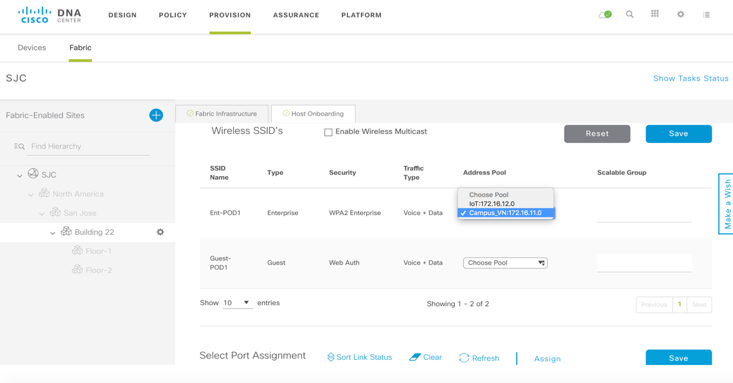
- Fabric SSID selection: For integrating SD-Access wireless with a fabric-enabled IP address pool (and VN).
- Static port settings: This allows custom IP address pool (and VN) and SGT settings at port level.
After the overlay is provisioned, IP address pools must be added and assigned to Virtual Networks to enable hosts to communicate within the fabric.
When an IP pool is configured in SD-Access, Cisco DNA Center immediately connects to each edge node to create the appropriate switch virtual interface (SVI) to allow the hosts to communicate.
In addition, an Anycast Gateway is configured for each IP pool on all Edge nodes within the Fabric domain. This is an essential element of SD-Access, because it allows hosts to easily roam to any Edge node with no additional provisioning.
Authentication template selection
Click on Fabric and under Host On-boarding select Closed Authentication template and Save and Apply.

Virtual networks and IP pools selection
We will now assign the IP pools to the created VNs.
As mentioned earlier, the AP’s and Extended Nodes (not used in this article) will be part of the INFRA_VN for Cisco DNA Center’s PnP host on-boarding feature. Click on the Infra-VN and click on Add on top right.

In the Add IP Pool section, Select the AP-Pool from the drop down menu of IP. Ensure AP is selected as the Pool Type. Also, make sure that AP-Pool is only a IPv4 pool and not dual stack as this is not supported currently. Click Update.

We can add more than one pool to the VN or hit x on top right to get to the main screen.

The VN will turn blue indicating there is an active IP Pool associated with it.

Repeat the steps for adding Campus IP Pool to Campus_VN, IoT IP Pool under IoT VN and Guest IP Pool under Guest_VN. However, select Data as the Traffic Type.


Fabric SSID selection
SD-Access allows for consistent policies across wired and wireless networks. SD-Access also allows for the same IP Pool and VN’s to be applied for both wired and wireless. In this next step, we will be applying the same VN and IP Pool used for Wired to the Ent-POD1 SSID. For the Ent-POD1 SSID, select Campus_VN Host Pool from the drop-down as shown below.

Similarly, select Guest_VN Address Pool from the dropdown for Guest-POD1 to assign the Guest_VN and associated IP Pool to be used for the Guest SSID.

Port Assignment
The topology has 2 Windows PC connected to both FE switches on Gig1/0/3 on both.
Cisco DNA Center allows authentication templates to be applied to all Edge nodes and all ports through the global template that we did earlier as well as over-riding that to select specific Edge nodes and ports to have a different type of Authentication template. For the AP, we will be using the No Authentication security template, which is different from the global authentication template configured earlier (Closed Authentication). Scroll to the bottom of the Host Onboarding page.
In the Select Port Assignment area, choose FE1-9300-03 from the left-hand side and select ports GigabitEthernet1/0/3 and click Assign.

In the side window that opens, from the Connected Device Type drop-down list, choose User Devices. In Address Pool, select Campus-Pool or IoT-Pool. From the Auth Template drop-down list, choose Closed Authentication. Click Update.

Verify the config and Apply to push the configuration to the Edge switches.


Do the same for 2nd FE switch – FE2-9300-04.
