- Cisco Community
- Technology and Support
- Networking
- Networking Knowledge Base
- Meraki Wireless deployment over Cisco SDA Fabric
- Subscribe to RSS Feed
- Mark as New
- Mark as Read
- Bookmark
- Subscribe
- Printer Friendly Page
- Report Inappropriate Content
- Subscribe to RSS Feed
- Mark as New
- Mark as Read
- Bookmark
- Subscribe
- Printer Friendly Page
- Report Inappropriate Content
on 04-01-2024 10:54 AM
- Introduction
- Validated Design
- Traffic Flow in Cisco Wireless SD-Access solution
- Meraki Wireless Design Fundamental
- Meraki Device-to-Cloud Communications
- Lab Setup
- Configuration
- Validation
Introduction
With the evolution of software defined networking (SDN) and cloud native technologies, every organization is looking for a network solution in their campus which has following characteristics:
- Simplified design
- Zero touch deployment
- Easy to operate
- Minimum operational overhead
- Centralized management
- User & endpoint mobility across the campus
Cisco offers combination of Meraki wireless and SDA fabric solution for large to medium size customers to achieve all the above mentioned characteristics of campus network solution.
Cisco Meraki cloud managed WiFi access points (AP) are easy to manage enterprise wireless LAN and other side Cisco Software Defined Access (SDA) is very popular software defined campus access networking solution. Thus, many Cisco customers are looking forward to deploy Meraki WiFi AP over SDA campus.
This document describes validated design with Control, data and management packet flows, software and hardware details used during testing, step by step on-boarding configuration and detailed test procedure to validate successful on-boarding of Meraki AP onboard over Cisco SDA Fabric.
Validated Design
Before going into the configuration and testing steps, lets first understand the existing SDA Fabric wireless design and Meraki wireless design. After having clear understanding of both the wireless network design, you will learn configuration and testing of Meraki wireless over SDA fabric.
Traffic Flow in Cisco Wireless SD-Access solution
SDA wireless solution is controller managed solution, where in AP is wireless extender of wireless controller. All the management, control and data traffic flow through controller, as depicted in diagrams below.
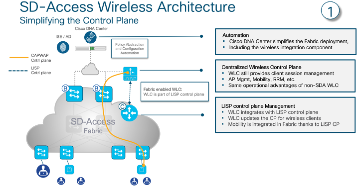
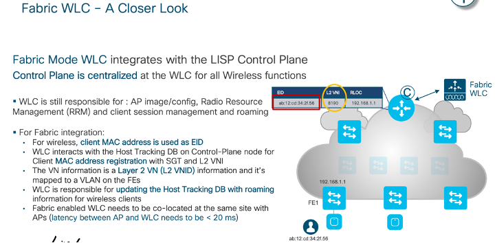
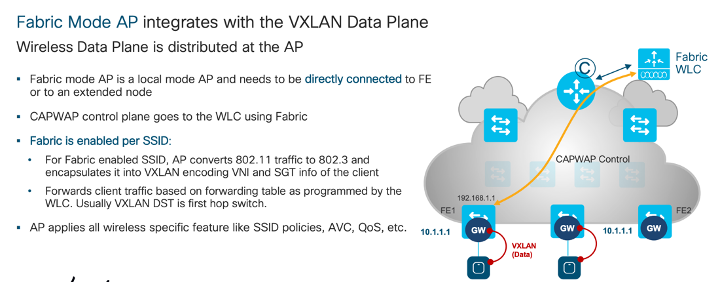
Meraki Wireless Design Fundamental
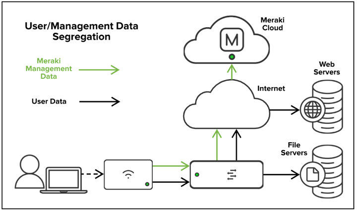
Management data: The data (configuration, statistics, monitoring, etc.) that flows from Meraki devices (wireless access points, switches, security appliances) to the Meraki cloud over a secure internet connection.
User data: Data related to user traffic (web browsing, internal applications, etc.). User data does not flow through the Meraki cloud, instead flowing directly to their destination on the LAN or across the WAN.
Meraki Device-to-Cloud Communications
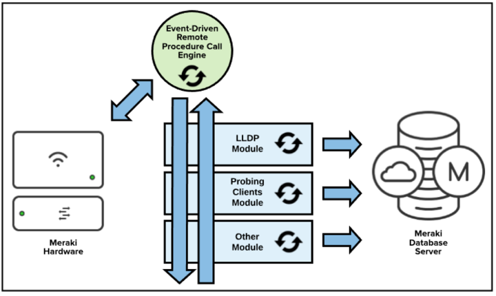
Meraki uses an event-driven remote procedure call (RPC) engine for Meraki devices to communicate to the dashboard and for Meraki servers to send and receive data. Meraki hardware devices act as the server/receiver as the Meraki cloud initiates calls to the devices for data collection and configuration deployment. The cloud infrastructure is the initiator, so configurations can be executed in the cloud before the devices are actually online or even physically deployed.
Lab Setup
Now, lets see how this hybrid solution can be deployed and tested.
This solution design is tested in lab environment where following hardware and software version are used:
- Cisco Catalyst Center running with software version 2.3.3.7
- Catalyst 9500 running with software version 17.9.3 and acting as Fabric Border and control node
- Catalyst 9300 running with software version 17.9.3 and acting as Fabric Edge
- Meraki APs MR42 running with software version MR 29.6.1 and managed from Meraki Dashboard
Below is the Physical diagram of the Meraki AP with SDA infrastructure used for the testing.
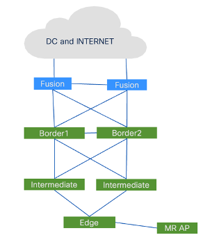
Lab setup is created with standard SDA design where Border and control functionalities are running on Catalyst 9500 and fabric edge node is running with Catalyst 9300. Meraki AP MR series is connected to fabric edge.
Configuration
In lab configuration, below steps were followed to onboard the Meraki APs in SDA Fabric:
- Configure multicast in underlay: The First step is to configure multicast routing in Underlay. Border(s) needs to be RPs for this underlay multicast configuration.
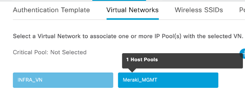
- Create a dedicated VN for Meraki AP management VLAN. In the lab we have configured Meraki_MGMT VN for the same
This is required due to a limitation in the Catalyst Center UI that the flooding on the AP Pool cannot be enabled.
- Configure L3 Hand off for above VM. L3 handoff for Meraki_MGMT VN is configured.
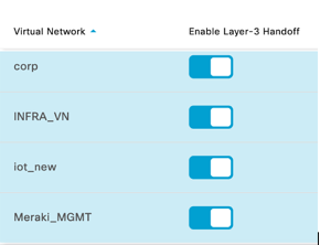
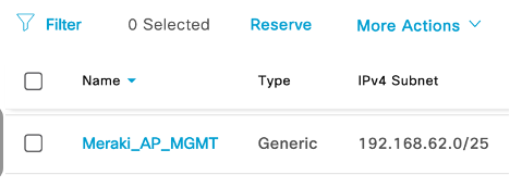
- Reserve ip pool and add it to above VN: An ip pool named Meraki_AP_MGMT has been reserved and added to Meraki_MGMT VN for Meraki AP management as per below screenshot.
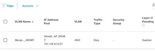
- Enable L2 flooding for the IP pool, Meraki_AP_MGMT, added in VN in above step.
- For Meraki client subnets add ip pools as L3. As per below screenshot we can see that Layer 2 only is Disabled.
- Configure switch ports for Meraki APs as trunk. Below is the sample configuration:
int gig1/0/20
switchport trunk native vlan 4062
switchport trunk allowed vlan 4062,24,99,1023
switchport mode trunk
spanning-tree bpduguard enable
- Make sure VLANs/SSIDs on Meraki configuration match what is configured from Cisco Catalyst Center on switches.
- IP_DT policy that Cisco Catalyst Center pushes as part of base provisioning on the port on FE where the Meraki APs are connected needs to be removed.
int gig1/0/20
no device-tracking attach-policy IPDT_POLICY
Validation
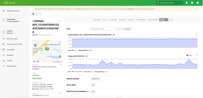
After configuring above steps we can see that AP is reachable and available in Meraki dashboard. AP has got IP address from the ip pool, Meraki_AP_MGMT, that was configured in Cisco catalyst center. From Meraki dashboard we can ping IP address of the AP.
- Mark as Read
- Mark as New
- Bookmark
- Permalink
- Report Inappropriate Content
Really helpful in deploying the meraki wireless in SDA fabric.
- Mark as Read
- Mark as New
- Bookmark
- Permalink
- Report Inappropriate Content
It will be good to cover other details like how the Data plane connection from Meraki AP is different to Fabric Edge compared to Catalyst AP. example - Catalyst AP (FEW) mode will create the VXLAN with the Fabric edge when connected directly or when behind Extended nodes. Authors should also include ports/protocols that need to be opened to allow communication from MR APs to the Meraki cloud.
- Mark as Read
- Mark as New
- Bookmark
- Permalink
- Report Inappropriate Content
Great document. Can you apply and enforce an SGT tag policy to an authorized wireless endpoint connected to a Meraki AP in the SDA environment?
- Mark as Read
- Mark as New
- Bookmark
- Permalink
- Report Inappropriate Content
What's the reason we need the remove the IPDT policy with the command:
no device-tracking attach-policy IPDT_POLICY
Is it for roaming?
Do you also need to enable the Intra-Subnet Routing?
- Mark as Read
- Mark as New
- Bookmark
- Permalink
- Report Inappropriate Content
They didn't mention enabling the intra-subnet routing, you probably don't need this because the endpoints will go on a VN of your choice and the Meraki AP's don't need to talk to each other
Find answers to your questions by entering keywords or phrases in the Search bar above. New here? Use these resources to familiarize yourself with the community:

