- Cisco Community
- Technology and Support
- Networking
- Networking Knowledge Base
- Recognize the purpose & functions of various network devices:Router, Switch, Hub & Bridge.
- Subscribe to RSS Feed
- Mark as New
- Mark as Read
- Bookmark
- Subscribe
- Printer Friendly Page
- Report Inappropriate Content
- Subscribe to RSS Feed
- Mark as New
- Mark as Read
- Bookmark
- Subscribe
- Printer Friendly Page
- Report Inappropriate Content
04-11-2016 03:44 PM - edited 03-01-2019 05:07 PM
We are going to start, slowly but surely, building a theoretical network in our minds. In order to do this, we are going to start from the beginning; recognizing all the components of a modern network as well as some not so modern devices. For now, it is going to be a basic description of each device's function, but we will elaborate on each concept as we move forward. Let's begin.
SWITCH:

The Switch is the star of the network, it is the most active device, in charge of making sure that frames go where they need to go These frames are units of data at Layer 2 (the Data-Link layer), of the 7 layers OSI reference model, and this is why switches are refer to as “Layer 2 devices”. A frame comes into one of the ports, and the switch “switches” the frame out of another port that points to the frame's final destination. This is possible because switches actively learn MAC addresses (a MAC address is the physical address of a device) and they keep a table, called the “MAC Table”, with entries matching MAC - to - port, so switches know off of which port, devices are reachable.
You should also know about how a Switch communicates. There are two communication methods; Half-Duplex and Full-Duplex and Switches communicate at Full-Duplex. This means that each one of its ports is able to send and receive data at the same time and this is because in Full-Duplex communication, two wires (inside the network cable) are used, one for transmitting and the other for receiving. This communication type makes it impossible for Collision to occur.
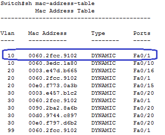
Here is an example of a “MAC Table”:

This is the table a switch builds with MAC address information taken from the frames that it receives on its ports. To look at this table, you issue the command “show mac-address-table” on a switch and you'll get the output above. Let's break it down:
Vlan: The frame received belongs to Vlan 10.
Vlans is a topic for future discussions and it is not needed to understand the function and inner workings of a Switch.
MAC Address: The frame received has a source MAC address of 0060.2fcc.9102.
In other words, the switch received a frame on port Fa0/1 and the device (PC, Router, another Switch, etc.) that sent this frame has this MAC address, so the Switch says; “Hey! A networked device that has the physical address of 0060.2fcc.9102 is connected to me and I can get to it from one of my ports” and adds that entry to its MAC table.
Type: How this MAC address was learned.
There two ways a Switch can learn MAC information; DYNAMIC, the Switch learns through frames received on its ports or, STATIC, the entry was manually configured.
Ports: On which port the frame came into the Switch.
This is the final piece of information needed. Now the Switch knows that a device with MAC address 0060.2fcc.9102 lives off of port Fa0/1. So, from now on, when the Switch receives a frame destined for 0060.2fcc.9102, it will immediately forward that frame out of port Fa0/1.
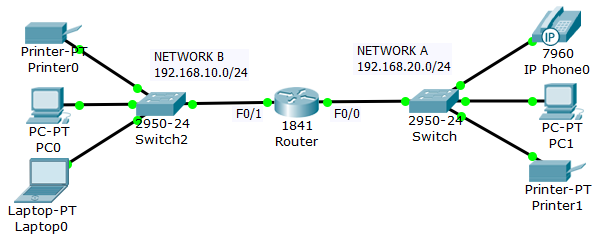
Switches are used to connect network devices, like this:

Now, notice that the Switch is connected to a Router. The Router, if needed, is used to get out of the local network (LAN) and access a different network. This may be another company's network or, most commonly, the Internet. Let's examine the Router next.
ROUTER:

Just like switches are used to connect devices, Routers are used to connect networks. Routers process packets, which are units of data at Layer 3, the Network layer, this is why Routers are refer to as “Layer 3 devices”. A Router receives a packet and examines the destination IP address information to determine what network the packet needs to reach, and then sends the packet out of the corresponding interface.

In the picture above, we have two different networks, that is Network A and Network B. In order for these two networks to be able to communicate with each other, a Router is needed to connect both networks.
For example, if PC1 wants to communicate with PC0, PC1 will send the data to the IP address of its Default-router, which in this case, is F0/0 on Router. When Router receives the packet, it examines the destination IP address contained in the packet and looks at its Routing Table to see if it knows where the destination network is located. In this case, it finds an entry in its Routing Table that says that network 192.168.10.0 is directly connected to interface F0/1, and so it sends the packet out of that interface.
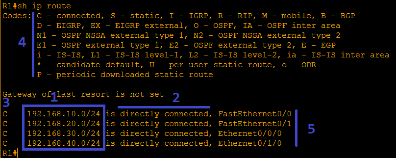
Here is an example of a “Routing Table”:

By issuing the command “show ip route” on a Cisco Router, we get the above output, let's see what it means; this particular Router knows about 4 networks, that is the 192.168.10.0, 192.168.20.0, 192.168.30.0 and the 192.168.40.0 networks (1). It happens to be that all 4 networks are directly connected to the Router as indicated (2) and also by the letter “C” (3). If the network was learned through a Routing Protocol (NOT directly connected), these lines will start with a different code (4). Finally, it shows to what interfaces are these networks connected (5).
So for example, the first lines reads; Network 192.168.10.0 is directly connected to interface FastEthernet0/0 and whenever the Router receives a packet destined for network 192.168.10.0, it knows to send it out of interface F0/0.
HUB:

A Hub, like a Switch, is used to connect multiple devices on a network, the difference is that Hubs are unintelligent devices, all they are able to do is replicate any frames they receive in one port, out of all the other ports. Hubs do not have the ability to learn MACs and make forwarding decisions as Switches do. The Hub works at Layer 1, the Physical layer, hence, it just deals with signals, it does not do any sort of processing on the signals it receives. In one port, out of the others.
The other big difference between a Hub and a Switch is the way it communicates. We said that a Switch communicates using the Full-Duplex method, the Hub on the other hand, uses the Half-Duplex method. This method uses only one wire inside the network cable to both transmit and receive, hence, the possibility of Collisions are much more greater on a Hub then on a Switch. In fact, Collisions are very common when a Hub is used, specially on large networks.
You will not see a Hub used in today's networks very often, but because Hubs are very cheap compared to Switches, you might come across a Hub in certain situation. A good scenario for implementing a Hub is, for example, a cubicle with a few end devices that need to connect to the network but there is only one network connector. You can just connect the Hub to the existing network jack and then the devices to the Hub, instead of having to run cabling from the Switch to the cubicle.
Note: if this is done unsupervised, it can potentially cause network disruptions, please seek the help of you IT department.
BRIDGE:
The Bridge, like a Switch, works at layer 2, the Data-Link layer. Bridges are even rarer than Hubs, almost obsolete we could say, but they were very popular during the early years due to the necessity to interconnect mixed network types such as Ethernet and Token-Ring and also, as networks started getting larger, it became necessary to break up Collision domains. A Collision happens when more than one device transmits data at the same time, and this can significantly slow a large network down. This is why Collision becomes an issue on large networks, the more devices trying to communicate, the greater the chances of Collisions.
* For more info on Collision Domains, read “Broadcast and Collision Domains”, in my blog @https://broadcaststormblog.wordpress.com/
However, on today's networks, Switches have made Bridges obsolete, let's see a few reasons:
- Ethernet became the most popular standard by far, so it is not very often that we need to connect different network types.
- Switch breaks up Collision domains.
- Switch has superior performance.
- Switch has lower per-port cost.
- Switch has higher port density. Most common Switches have 24 or 48 ports as opposed to 2 or 4 ports on a Bridge.
OK, we've talked about all the basic devices needed to build a basic network, let's go ahead a build one:
Find answers to your questions by entering keywords or phrases in the Search bar above. New here? Use these resources to familiarize yourself with the community: