- Cisco Community
- Technology and Support
- Networking
- Routing
- Re: Help me with Packet Tracer (2) .......
- Subscribe to RSS Feed
- Mark Topic as New
- Mark Topic as Read
- Float this Topic for Current User
- Bookmark
- Subscribe
- Mute
- Printer Friendly Page
- Mark as New
- Bookmark
- Subscribe
- Mute
- Subscribe to RSS Feed
- Permalink
- Report Inappropriate Content
05-25-2020 03:33 AM - edited 05-25-2020 04:29 AM
Sir,
This is my 2nd issue.
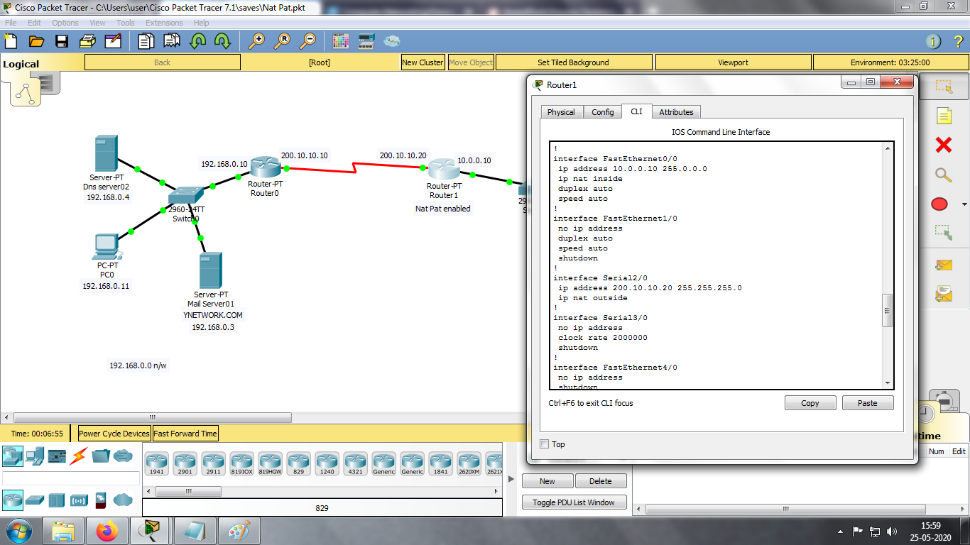
Here, Nat Pat is enabled in Router1.
But its not working. i can ping from 192.168.0.0 n/w to 200.10.10.20 (public ip of 10.0.0.0 n/w) But, cant neither access webserver nor sent mails to 10.0.0.0 n/w.
But static Nat works fine.
Nat Pat is not working.
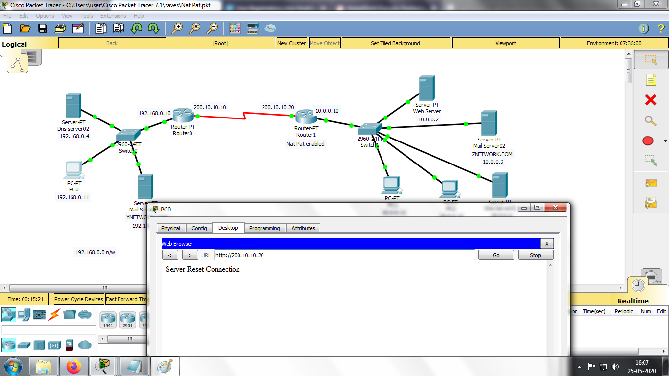
The output - When i access the webserver (10.0.0.2) from 192.168.0.11, the ouput is "Server Reset Connection".
Will be thankful if some1 could sole this.
Solved! Go to Solution.
- Labels:
-
Other Switching
Accepted Solutions
- Mark as New
- Bookmark
- Subscribe
- Mute
- Subscribe to RSS Feed
- Permalink
- Report Inappropriate Content
06-01-2020 03:42 AM
In your topology 10.0.0.0, 172.16.0.0 and 192.168.0.0 networks are private networks.
These IP address ranges are not allowed on the public internet. IP address 200.x.x.x is public address and is allowed on the internet.
You don't advertise private ip address 10,172.16, and 192.168 to the ISP. ISP gives you public ip address that you use to communicate over the internet.
So in your topology, Router0, Router1, Router2 are ISP routers with public IP address 200.x.x.x
When 10.0.0.0 network wants to communicate with 172.16 or 192.168 network the outgoing traffic needs to be natted on Router1 to appear or make it look like its coming from 200.10.10.0 and NOT from 10.0.0.0 because 10.0.0.0 will not be allowed to route over the internet. The same thing from the other side .. traffic from 172.16 or 192.168 going to 10.0.0.0 network will be natted on Router2 or Router0 respectively.
In your network you are advertising internal/private address (10,172.16,192.168) to the ISP. In real-world you don't advertise internal ip addresses .. you nat them on the router connected to the ISP.
Again in your example, the outgoing nat will be configured on Router0,1,2 to make all internal networks to make the appear coming from 200.x.x.x address.
As an example for 192.16 and 10.0 network
you only run rip for 200.x.x.x network
Router0
router rip
 network 200.10.10.0
 network 205.10.10.0

Router1
router rip
 network 200.10.10.0
and then to allow internet address to communicate configure nat
Router0
access-list 1 permit 192.168.0.0 0.0.255.255
ip nat inside source list 1 interface Serial2/0 overload

Router1
access-list 1 permit 10.0.0.0 0.0.0.255
ip nat inside source list 1 interface Serial2/0 overload
Now if you ping internal address for example 192.168.0.4 it will not work .. this is how real-world is .. you cannot ping internal addresses. But if you ping from PC1 10.0.11.11 to 200.10.10.10 and then run command show ip nat translations on Router1 you see
Router1(config)#do sh ip nat tr
Pro  Inside global     Inside local       Outside local      Outside global
icmp 200.10.10.20:18   10.0.0.11:18       200.10.10.10:18    200.10.10.10:18
icmp 200.10.10.20:19   10.0.0.11:19       200.10.10.10:19    200.10.10.10:19
icmp 200.10.10.20:20   10.0.0.11:20       200.10.10.10:20    200.10.10.10:20
icmp 200.10.10.20:21   10.0.0.11:21       200.10.10.10:21    200.10.10.10:21
tcp 200.10.10.20:25    10.0.0.3:25        ---                ---
tcp 200.10.10.20:80    10.0.0.2:80        ---                ---
10.0.0.11 pc address is natted to 200.10.10.20 which is the outgoing interface of Router1.
For incoming traffic to webserver or email we configure
ip nat inside source static tcp 10.0.0.2 80 200.10.10.20 80
ip nat inside source static tcp 10.0.0.3 25 200.10.10.20 25
which means that when someone tries to connect to 200.10.10.20 on port 80 send it to 10.0.0.2 port 80
because 10.0.0.0 network is not allowed on the internet.
Are you clear with all this so far?
- Mark as New
- Bookmark
- Subscribe
- Mute
- Subscribe to RSS Feed
- Permalink
- Report Inappropriate Content
05-25-2020 03:40 AM
- Mark as New
- Bookmark
- Subscribe
- Mute
- Subscribe to RSS Feed
- Permalink
- Report Inappropriate Content
05-25-2020 03:53 AM
zip and attach packet tracer file here
- Mark as New
- Bookmark
- Subscribe
- Mute
- Subscribe to RSS Feed
- Permalink
- Report Inappropriate Content
05-25-2020 04:22 AM
- Mark as New
- Bookmark
- Subscribe
- Mute
- Subscribe to RSS Feed
- Permalink
- Report Inappropriate Content
05-25-2020 07:45 AM
To send email for pc0 to pc1 .. add
ip nat inside source static tcp 10.0.0.3 25 200.10.10.20 25
to access the web server add
ip nat inside source static tcp 10.0.0.2 80 200.10.10.20 80
on the router with nat/pat enabled

- Mark as New
- Bookmark
- Subscribe
- Mute
- Subscribe to RSS Feed
- Permalink
- Report Inappropriate Content
05-29-2020 04:11 AM - edited 05-29-2020 04:27 AM
Sir,
Im thanking you for ur assistance.
As u mentioned, i configured the router with the 2 statements u mentiuoned in the reply :-
ip nat inside source static tcp 10.0.0.3 25 200.10.10.20 25
ip nat inside source static tcp 10.0.0.2 80 200.10.10.20 80
But, this is just port address translation u mentioned.
Yes, i can send mails from PC0 to PC1 & PC2
Yes, i can access the webserver too.
But, whats the need for "overload" statement ??
Bcoz, i ONLY entered the above 2 statements & i got the needed results.
& i didnt even configure the router's exit interface (Se2/0) as "overload" & i didnt copnfigure any access-lists too.
So, what im asking is - Whats the need for the "overload" statement ?? Where is that used ?
I studied that when we have only 1 private ip owned, we can configure that private ip as "overload" so all systems on 10.0.0.0 n/w can be accessed.
But, here we can access both the web server & the mail server with the pat configuration. Means there is no need for the overload statement.
Then in some example, i saw configuring access-lists too to access the every systems of 10.0.0.0 n/w.
So, what im saying is without the "overload" statement & "access-list" statement, it works fine.
So, in which condition is the "overload" statement & "access-list" statement used ??
I hope you understood my doubt.
Waiting to get it sorted soon .......
Stay Safe ......
- Mark as New
- Bookmark
- Subscribe
- Mute
- Subscribe to RSS Feed
- Permalink
- Report Inappropriate Content
05-30-2020 12:27 PM
Hi
NAT with Overload keyword is used for outgoing traffic to use PAT. One IP address and ports are used to for natting. You configure access-list to match the traffic you want to NAT.
What we have configured for mail and webserver is called port forwarding. This is not the same as outgoing NAT. Port forward is usually used for incoming traffic. In the static nat statements what we are saying is .. anything coming to 200.10.10.20 on port 25 send to10.0.0.3 on port 25 and the same for the web server.
Hope this helps ..
- Mark as New
- Bookmark
- Subscribe
- Mute
- Subscribe to RSS Feed
- Permalink
- Report Inappropriate Content
05-31-2020 05:10 AM - edited 05-31-2020 05:12 AM
Sir,
Thankyou for the reply. I read ur comment.
But i didnt understand it totally. You say that Nat Pat with "overload" statement is used for allowing traffic to outside.
To be frank, i didnt understand it when it comes to practical.
Can u give an example where "overload" & "access-list" is to be used ?
I have attached an upgraded packet tracer file.Please look into it.
I just configured nat pat in all routers (without the "overload" function). I can send mails & access the web server to & fro.
So, my question is In which condition the "overload" function is to be used ?
- Mark as New
- Bookmark
- Subscribe
- Mute
- Subscribe to RSS Feed
- Permalink
- Report Inappropriate Content
05-31-2020 09:57 AM
'Overloading' means that the single public IP assigned to your router can be used by multiple internal hosts concurrently. This is done by translating source UDP/TCP ports in the packets and keeping track of them within the translation table kept in the router.
- Mark as New
- Bookmark
- Subscribe
- Mute
- Subscribe to RSS Feed
- Permalink
- Report Inappropriate Content
05-31-2020 07:14 PM
Sir,
I dont want the definitions. But i didnt get the idea where it could be applied in practical. So, i need only examples related to practicals.
So, i beg u to give an example question related to my packet tracer project (which i have attached above) where "overload" can be used with.
- Mark as New
- Bookmark
- Subscribe
- Mute
- Subscribe to RSS Feed
- Permalink
- Report Inappropriate Content
06-01-2020 03:42 AM
In your topology 10.0.0.0, 172.16.0.0 and 192.168.0.0 networks are private networks.
These IP address ranges are not allowed on the public internet. IP address 200.x.x.x is public address and is allowed on the internet.
You don't advertise private ip address 10,172.16, and 192.168 to the ISP. ISP gives you public ip address that you use to communicate over the internet.
So in your topology, Router0, Router1, Router2 are ISP routers with public IP address 200.x.x.x
When 10.0.0.0 network wants to communicate with 172.16 or 192.168 network the outgoing traffic needs to be natted on Router1 to appear or make it look like its coming from 200.10.10.0 and NOT from 10.0.0.0 because 10.0.0.0 will not be allowed to route over the internet. The same thing from the other side .. traffic from 172.16 or 192.168 going to 10.0.0.0 network will be natted on Router2 or Router0 respectively.
In your network you are advertising internal/private address (10,172.16,192.168) to the ISP. In real-world you don't advertise internal ip addresses .. you nat them on the router connected to the ISP.
Again in your example, the outgoing nat will be configured on Router0,1,2 to make all internal networks to make the appear coming from 200.x.x.x address.
As an example for 192.16 and 10.0 network
you only run rip for 200.x.x.x network
Router0
router rip
 network 200.10.10.0
 network 205.10.10.0

Router1
router rip
 network 200.10.10.0
and then to allow internet address to communicate configure nat
Router0
access-list 1 permit 192.168.0.0 0.0.255.255
ip nat inside source list 1 interface Serial2/0 overload

Router1
access-list 1 permit 10.0.0.0 0.0.0.255
ip nat inside source list 1 interface Serial2/0 overload
Now if you ping internal address for example 192.168.0.4 it will not work .. this is how real-world is .. you cannot ping internal addresses. But if you ping from PC1 10.0.11.11 to 200.10.10.10 and then run command show ip nat translations on Router1 you see
Router1(config)#do sh ip nat tr
Pro  Inside global     Inside local       Outside local      Outside global
icmp 200.10.10.20:18   10.0.0.11:18       200.10.10.10:18    200.10.10.10:18
icmp 200.10.10.20:19   10.0.0.11:19       200.10.10.10:19    200.10.10.10:19
icmp 200.10.10.20:20   10.0.0.11:20       200.10.10.10:20    200.10.10.10:20
icmp 200.10.10.20:21   10.0.0.11:21       200.10.10.10:21    200.10.10.10:21
tcp 200.10.10.20:25    10.0.0.3:25        ---                ---
tcp 200.10.10.20:80    10.0.0.2:80        ---                ---
10.0.0.11 pc address is natted to 200.10.10.20 which is the outgoing interface of Router1.
For incoming traffic to webserver or email we configure
ip nat inside source static tcp 10.0.0.2 80 200.10.10.20 80
ip nat inside source static tcp 10.0.0.3 25 200.10.10.20 25
which means that when someone tries to connect to 200.10.10.20 on port 80 send it to 10.0.0.2 port 80
because 10.0.0.0 network is not allowed on the internet.
Are you clear with all this so far?
- Mark as New
- Bookmark
- Subscribe
- Mute
- Subscribe to RSS Feed
- Permalink
- Report Inappropriate Content
06-01-2020 03:44 AM
- Mark as New
- Bookmark
- Subscribe
- Mute
- Subscribe to RSS Feed
- Permalink
- Report Inappropriate Content
06-09-2020 01:06 AM
Hi
Did you read/understand my last reply?
Thanks
- Mark as New
- Bookmark
- Subscribe
- Mute
- Subscribe to RSS Feed
- Permalink
- Report Inappropriate Content
06-25-2020 09:43 PM
Sir,
So sorry that i couldn't keep in touch.Had a tough time last few weeks. My system went down & due to the Pandemic outbreak, i couldn't get the system repaired quickly as my region is strictly monitored. Only got the system all set 2 days b4. I saw ur detailed explanation & understood it completely. I know the effort u took to get it explained & i just couldn't follow it with the response. Feel sorry for that.
Yes, i went thought ur explanation & i configured with my network design. I knew that private ip's wont be allowed outside lan but i couldnt implement it practically.
I only understood it from ur explanation & i understood it completely. But i couldnt look into the example packet tracer file which u have attached. It had compatibilty issues. I think u r using mac & im using windows 32 bit. But im cleared with ur explanations. so, no worries.
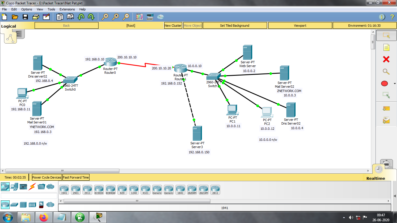
But i came up with new doubt. I have attached my packet tracer file with updated configurations.
Router 0, Router 1 are configured with nat pat overload functions.
Everything is working fine. Cant sent mails each other & can access the web server each other with the public ips 200.10.10.10 , 200.10.10.20.
My doubt :
Suppose router 1 a lan router, i configured another network - 192.168.0.0 & configured another web server 192.168.0.150. How can any public pc access the the webserver 192.168.0.150 ? If my knowledge is right, there should be another public ip for the 192.168.0.0 n/w.
So, my doubt is how the router 1 has to be configured to accesss the 192.168.0.150 webserver ?
Dont know whether im wrong, i tried with dynamic nat configurations - by creating pool but it couldnt get the desired results.
Can u solve this ?
- Mark as New
- Bookmark
- Subscribe
- Mute
- Subscribe to RSS Feed
- Permalink
- Report Inappropriate Content
06-27-2020 01:36 AM
Sir,
In my last reply, i asked how i could add an extra web server in another n/w.
I guess i found the answer. I'm attaching the updated packet tracer file. Please look into that & reply whether my findings are correct or not.
Actually i configured another public ip (50.0.0.20) in serial3/0 interface of router.
& configured static nat & access-list with a new number for the 192.168.0.0 n/w.
Below are my configurations.
router rip
network 50.0.0.0
network 200.10.10.0
!
ip nat inside source list 20 interface Serial3/0 overload
ip nat inside source list 5 interface Serial2/0 overload
ip nat inside source static tcp 10.0.0.3 25 200.10.10.20 25
ip nat inside source static tcp 10.0.0.2 80 200.10.10.20 80
ip nat inside source static tcp 192.168.0.150 80 50.0.0.20 80
ip classless
!
ip flow-export version 9
!
!
access-list 5 permit 10.0.0.0 0.255.255.255
access-list 20 permit 192.168.0.0 0.0.0.255
Now i could access the webserver 10.0.0.2 with the public ip 200.10.10.20 &
webserver 192.168.0.150 with the public ip 50.0.0.20
I dont know whether my logic is right or not. Thats what im asking u.
If this logic is right, then what i want to know is :
Suppose i own 10 websites & if i need to host to public, then i need 10 public ip. Right ?
So, i need to know wthethr i need 5 routers for that. because each public ip have to be configured on each router's serial interface. Here, the router have only 2 serial interfaces. So, i need 5 routers to host 10 websites. Am i right with this ? Or is there any logic applied for this ??
& i need to know in whats the use of dynamic nat if any system can access the internet when nat pat overload is configured.
Hope u understood my doubts.
Hope u reply .......
Discover and save your favorite ideas. Come back to expert answers, step-by-step guides, recent topics, and more.
New here? Get started with these tips. How to use Community New member guide