- Cisco Community
- Technology and Support
- Security
- Security Knowledge Base
- CSM: How to configure 8.3+ NAT using CSM 4.x
- Subscribe to RSS Feed
- Mark as New
- Mark as Read
- Bookmark
- Subscribe
- Printer Friendly Page
- Report Inappropriate Content
")
- Subscribe to RSS Feed
- Mark as New
- Mark as Read
- Bookmark
- Subscribe
- Printer Friendly Page
- Report Inappropriate Content
09-16-2011 01:34 PM - edited 08-29-2017 12:17 AM
Documentation
This configuration example is meant to be interpreted with the aid of the official documentation from the configuration guide located here:
http://tools.cisco.com/squish/1723D
Prerequisite
- CSM 4.0.1 support ASA Software Release 7.0(1-2, 4-8), 7.1(1-2), 7.2(1-5), 8.0(2-3, 5), 8.1(1-2), 8.2(1-2), and 8.3(0).
http://tools.cisco.com/squish/107d5 - CSM 4.1 supports ASA Software Release 7.0(1-2, 4-8), 7.1(1-2), 7.2(1-4), 8.0(2-3, 5), 8.1(1-2), 8.2(1-3), 8.3(1-2), 8.4(1).
http://tools.cisco.com/squish/a04ca
Types of NAT configuration
Dynamic PAT hide (Object NAT or Auto NAT)
The following steps are assuming the fact that the ASA has been succefully discovered and brought into CSM. Let us say the following from CLI, needs to be created and deployed from CSM. All inside hosts will be PAT-ed to the outside interface IP address while going out to the internet. Please refer this link for more information: http://tools.cisco.com/squish/D23Ae
ect network obj_any
subnet 0.0.0.0 0.0.0.0
object network obj_any
nat (inside,outside) dynamic interface
1. Click on the Policy Object Manager (Manage >>Policy Objects)

2. Choose Networks/Hosts on the left pane and click the "+" to add and add the inside network.

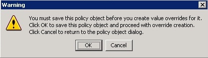
3. Add the network. You can specify certain subnet like 192.168.1.0 with a mask 255.255.255.0 or inlcude simply use 0.0.0.0 with a mask 0 which will include all networks. Make sure to chick the "Allow value override per Device" since this will be specific to this firewall.
4. Accept the warning message about saving. If you have similar objects with the same content you may see another warning as well.

5. Choose the firewall that is being configured and click OK.

6. Configure the NAT tab per the screen shot below. Submit and deploy

Static PAT to the interface or a specific address with Port Translation
Allow VNC to this host 192.168.2.2 from the outside on port 5900
object network obj-192.168.2.2-01
host 192.168.2.2
object network obj-192.168.2.2-01
nat (inside,outside) static interface service tcp 5900 5900
1. Familiarize with the screen shots shown in the Dynamic PAT section above. We will simply go over the same steps and only include the
differences via a screen shot. Let us follow the same steps as before. Click on the Pollicy Object Manager or (Manage >>Policy Objects)
2. Choose Networks/Hosts on the left pane and click the "+" to add and add the inside host
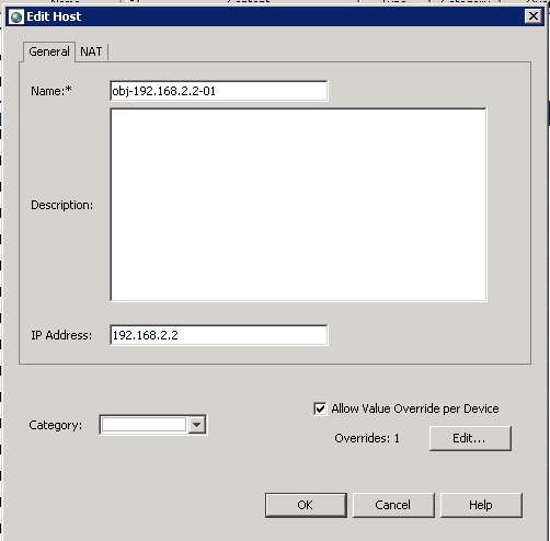
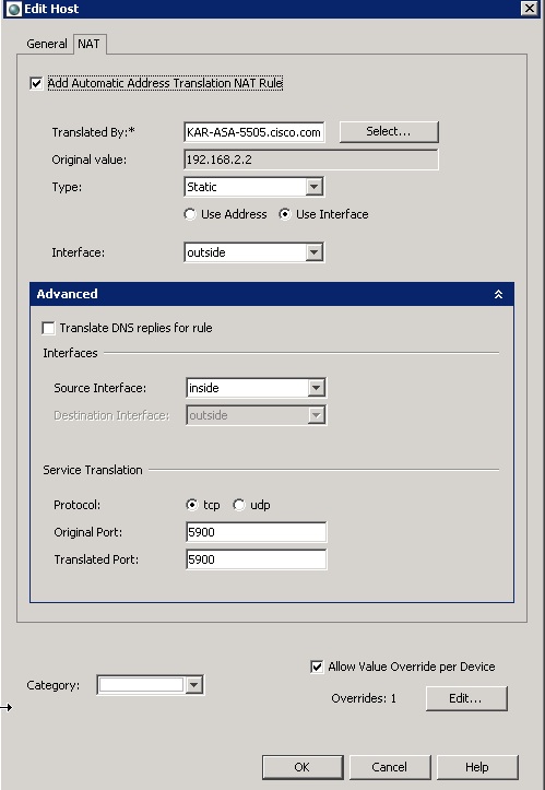
3. Configure the NAT tab to allow for VNC to this host 192.168.2.2 from the outside to port 5900. Watch the type as "Static" and choose interface and pick the outside interface. Choose "use address" if needed instead of "Use Interface".
Use service translation for tcp port 5900.
4. The rest of the steps are very similar to the steps that is listed for Dynamic PAT. Finish the rest of the config and deploy.
Static Policy NAT
object host obj-192.168.2.2
host 192.168.2.2
object network obj-192.168.100.100
host 192.168.100.100
object network obj-10.76.5.0
subnet 10.76.5.0 255.255.255.224
nat (inside,outside) source static obj-192.168.2.2-14 obj-192.168.100.100
destination static obj-10.76.5.0 obj-10.76.5.0
When the source 192.168.2.2 goes out to a destination network 10.76.5.0/24, make the source look like 192.168.100.10.
- Please review the screen shots under the Dynamic PAT section and get familiarized. Click the "Policy Object Manager" and add
a. 2 host objects (for source IP and translated address for source IP)
b. 1 network (destination address that the souce will try to reach). Make sure to indicate 27 for mask.
Make sure to choose "Allow Value Override Per Device" if this object will specifically be used only with this firewall and map it to this firewall as per the screen shots shown in dynamic PAT section. - Close out of the "Policy Object Manager" and click the "NAT" option on the left pane and choose "Translation Rules".
- Now, configure the static policy manual NAT. Pick the source object, mapped IP for the source object and the destination network that the
source will try to reach. Click OK and save the config and deploy. You can choose either "NAT Rules Before" or "NAT Rules After". Depending on what you choose it will be process before or after auto NAT. Make sure to specify source and destination interface.

Identity NAT (policy)
When the source network 192.168.2.0/24 tries to reach the remote subnet 10.10.10.0/24, keep the original source IP address and do not translate.
Refer this link for more information: http://tools.cisco.com/squish/9ee8d
object network obj_any-01
subnet 192.168.2.0 255.255.255.0
object network obj_remote
subnet 10.10.10.0 255.255.255.0
nat (inside,outside) source static obj_any-01 obj_any-01 destination static obj_remote obj_remote
1. Please watch the screen shots provided in Dynamic PAT above . Click the "Policy Object Manager" and add two network objects
a. one for 192.168.2.0 255.255.255.0 and the other for 10.10.10.0 255.255.255.0
2. Once that is done cose out of "Policy Object Manager" and click the "NAT" on the left pane and choose "Tranlation Rules".
3. Then choose "After" or "Before" NAT Rules and follow the below screen shot. Submit and Deploy. Make sure to specify the source and destination interface. If the source has to look like itself when it goes out any other interface then, we could use the word "Any" instead of "outside" for the destination interface.
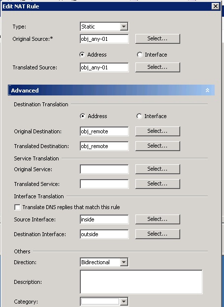
Note: If you do not want to do policy then, do not specify the Original and Translated destination.
Static NAT
The following will translate the host 10.10.10.35 to look like 172.18.254.35 when going out via "Any" interface.
object network www_server
host 10.10.10.35
object network mappedIP
host 172.18.254.35
nat (dmz,any) source static web_server mappedIP
1. Please watch the screen shots provided in Dynamic PAT above. We need to create 3 host objects using the "Policy Object Manager".
a. one host object for the real address on the dmz 10.10.10.35
b. one host object for mappedIP 172.18.254.35
2. Once that is done cose out of "Policy Object Manager" and click the "NAT" on the left pane and choose "Tranlation Rules".
3. Then choose "After" or "Before" NAT Rules which ever you require (depending on what is chosen this nat will be processed after the auto nat or before the auto nat) and follow the below screen shot. Submit and Deploy. Specify the source interface as "dmz" and destination interface as "Any". Save the config. Make sure to pick the type as Static.

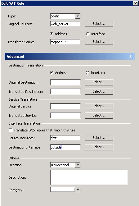
Static NAT - translate a dmz host to be reachable via two different IPs from the outside
How to accomplish what is depicted in the blog http://tools.cisco.com/squish/5842D via CSM
object network web_server
host 192.168.99.23
object network mappedIP-1
host 209.165.201.32
object network mappedIP-2
host 209.165.201.42
!
nat (dmz,outside) source static web_server mappedIP-1
nat (dmz,outside) source static web_server mappedIP-2
1. Please watch the screen shots provided in Dynamic PAT above. We need to create 3 host objects using the "Policy Object Manager".
a. one host object for the real address on the dmz
b. one host object for mapped IP1
c. another host object for mapped IP2
2. Once that is done cose out of "Policy Object Manager" and click the "NAT" on the left pane and choose "Tranlation Rules".
3. Then choose "After" or "Before" NAT Rules and follow the below screen shot. Submit and Deploy. Specify the source interface as dmz and destination interface as outside. Save the config.
4. Repeat step 3 for mappedIP-2 as below. Save the config and deploy.

- Mark as Read
- Mark as New
- Bookmark
- Permalink
- Report Inappropriate Content
Great Document ! Extremely useful.
Find answers to your questions by entering keywords or phrases in the Search bar above. New here? Use these resources to familiarize yourself with the community: