- Cisco Community
- Technology and Support
- Service Providers
- Service Providers Knowledge Base
- ASR9000/XR: How to use Port Spanning or Port Mirroring
- Subscribe to RSS Feed
- Mark as New
- Mark as Read
- Bookmark
- Subscribe
- Printer Friendly Page
- Report Inappropriate Content
- Subscribe to RSS Feed
- Mark as New
- Mark as Read
- Bookmark
- Subscribe
- Printer Friendly Page
- Report Inappropriate Content
on
03-20-2011
10:04 AM
- edited on
12-22-2017
09:20 AM
by
Gagandeep Kaur
![]()
Introduction
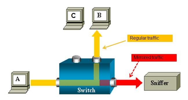
This document provides some extra documentation and use cases on the use of port spanning or port mirroring.
You can monitor traffic passing in & out of a set of L2 or L3 Ethernet interfaces (including bundle-Ether).
Core Issue
ASR 9000 is the only platform implementing SPAN on XR (Only support on ethernet linecards, not on SIP-700.)
You can use SPAN/Mirror in the follow scenarios
- L2 & L3 interfaces.
- Local, R-SPAN, and PW-SPAN only (no ER SPAN.)
- Scale limits:
8 monitor sessions
800 total source ports
1.5 Gig bidirectional replication limit toward fabric for bundle interfaces and 10 Gig ports.
Guideline: ~ 10% - 15% total bandwidth can be mirrored system-wide
- Source ports: Physical, EFPs, and bundles interfaces (L2 & L3)
- Destination ports: Ethernet interfaces, EFPs, and PW-SPAN. (No bundle) [ only L2 transport interfaces are supported as destination ports]
- Ability to use ACL's to define which traffic is to be captured
- Capture multicast traffic is possible
Note: some of the functionality mentioned are enhancements to the XR 4.0.1 release, this document assumes you are using this release or later.
A good reference on the terminology of SPAN/Mirror can be found here:
http://www.cisco.com/en/US/docs/switches/lan/catalyst6500/ios/12.2SX/configuration/guide/span.pdf
SPAN order of operation
SPAN mirrors what is on the wire
For ingress, this means packets are mirrored before QOS, ACL, and encapsulation rewrite operations.
For egress, this means packets are mirrored after QOS, ACL, and encapsulation rewrite operations.
Partial Packet Mirroring
User can configure to mirror first 64 upto 256 bytes of the packet.
Note: The actual mirrored packet will be the configured size plus 4-byte trailling CRC.
Sample config:
interface GigabitEthernet0/6/0/20 l2transport
monitor-session PW
mirror first 100 <== valid range: [64, 256], inclusively
!
!
Note: The mirrored packet received at sniffer will have the size of 104
(4-byte of trailing CRC added by transmit MAC layer.)
ACL based Mirroring
“permit/deny” determines the behavior of the regular traffic (forwarded or dropped)
“capture” determines whether the packet is mirrored to the SPAN destination.
On SPAN: mirror traffic on the wire (regardless with or without ACL.)
ACL on ingress direction:
SPAN will mirror traffic even regular traffic dropped by ACL: Always mirror!
ACL on egress direction
Will mirror if regular traffic is forwarded (Permit)
Will not mirror if regular traffic is dropped (Deny.)
Inconsistent configurations:
“acl” is configured on SPAN source port but
ACL has no “capture” keyword:
No traffic gets mirrored.
“acl” is NOT configured on SPAN source port but
ACL has “capture” keyword:
Mirroring traffic as normal, no ACL performed.
The ACL can also be an L2 ACL :
ethernet-services access-list esacl_t2
10 deny 1234.5678.90ab 0000.0000.0000 any capture
L3 Spanning Example
monitor-session TEST
destination interface GigabitEthernet0/1/0/2 (<<<< this is NP3)
!
interface GigabitEthernet0/1/0/14 (<<<< this is NP2)
ipv4 address 5.5.1.1 255.255.255.0
monitor-session TEST
acl
!
load-interval 30
ipv4 access-group span ingress
!
ipv4 access-list span
10 permit ipv4 any host 1.1.1.10 capture
15 permit ipv4 any host 239.1.1.1 capture
20 permit ipv4 any host 2.2.2.100
30 permit ipv4 any any
Sample TRAFFIC GEN: (sending multicast in this example)
tgn rate 1000
L2-dest-addr 0100.5E01.0101
L2-src-addr 0003.A0FD.28A8
L3-src-addr 5.5.1.2
L3-dest-addr 239.1.1.1
Checking NP2: (the port that we are spanning)
Show global stats counters for NP2, revision v3
Read 12 non-zero NP counters:
Offset Counter FrameValue Rate (pps)
-------------------------------------------------------------------------------
22 PARSE_ENET_RECEIVE_CNT 5478 1001
31 PARSE_INGRESS_DROP_CNT 3 1
33 RESOLVE_INGRESS_DROP_CNT 5474 1000
(there is no mcast recipient for this mcast addr, but we’re still replicating, see red line)
40 PARSE_INGRESS_PUNT_CNT 1 0
50 MODIFY_RX_SPAN_CNT 5475 1000
54 MODIFY_FRAMES_PADDED_CNT 5475 1000
68 RESOLVE_INGRESS_L3_PUNT_CNT 1 0
104 LOOP 1 0
224 PUNT_STATISTICS 9 2
480 RESOLVE_IPM4_ING_RTE_DROP_CNT 5475 1000
565 UIDB_TCAM_MISS_AGG_DROP 3 1
570 UIDB_TCAM_MISS_PORT4_DROP_FOR_HOST 3 0
NP3 is the span monitor interface:
Show global stats counters for NP3, revision v3
Read 16 non-zero NP counters:
Offset Counter FrameValue Rate (pps)
-------------------------------------------------------------------------------
22 PARSE_ENET_RECEIVE_CNT 36 0
23 PARSE_FABRIC_RECEIVE_CNT 79656 1000
30 MODIFY_ENET_TRANSMIT_CNT 79655 1000
Packets received from fabric and sent off to the Ethernet on the span port!
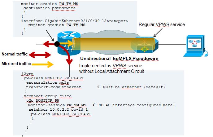
PW SPAN example
For PW span to work, you need to define a local monitor session with a destination pseudo wire. You apply that span session to the interface of interest and define an xconnect group that also leverages that span session as one of the pw ends.
On the remote side where the PW terminates, you just configure regular VPWS.
Here an example:
On the Local Side, besides my Span configuration, there is also a local cross connect between the interested session we want to span over the PW
l2vpn
xconnect group TEST
p2p TEST
interface GigabitEthernet0/1/0/39
! port 39 is the port where we apply the span on.
interface GigabitEthernet0/1/0/20.100
! this is just a random AC to have traffic flowing between the spanned port.
!
AC configuration:
interface GigabitEthernet0/1/0/20.100 l2transport
encapsulation dot1q 100
rewrite ingress tag pop 1 symmetric
! the tag is popped because the other XCON end is a plain ethernet without vlan. The explanation and use cases of tag popping can be found a related
! Tech note article.
Configuration on the remote side:
Regular VPWS configuration:
RP/0/RSP0/CPU0:A9K-TOP#sh run l2vpn
l2vpn
xconnect group PW-SPAN
p2p PW-SPAN_1
interface GigabitEthernet0/0/0/39
neighbor 2.2.2.2 pw-id 1
!
!
!
interface GigabitEthernet0/0/0/39
load-interval 30
transceiver permit pid all
l2transport
!
!
the neighbor in the l2vpn configuration is the LDP neighbor ID
between which the PW is built.
Show on remote side:
RP/0/RSP0/CPU0:A9K-TOP#show l2vpn xcon group PW-SPAN det
Group PW-SPAN, XC PW-SPAN_1, state is up; Interworking none
AC: GigabitEthernet0/0/0/39, state is up
Type Ethernet
MTU 1500; XC ID 0x4000a; interworking none
Statistics:
packets: received 0, sent 16570475
bytes: received 0, sent 994228500
! packets received from the PW are sent out hte Attachment circuit's interface. The analyzer is connected to G0/0/0/39
PW: neighbor 2.2.2.2, PW ID 1000, state is up ( established )
PW class not set, XC ID 0x4000a
Encapsulation MPLS, protocol LDP
PW type Ethernet, control word disabled, interworking none
PW backup disable delay 0 sec
Sequencing not set
MPLS Local Remote
------------ ------------------------------ -----------------------------
Label 16002 16027
Group ID 0xa40 0x2
Interface GigabitEthernet0/0/0/39 PW/TM/MS
MTU 1500 1500
Control word disabled disabled
PW type Ethernet Ethernet
VCCV CV type 0x2 0x2
(LSP ping verification) (LSP ping verification)
VCCV CC type 0x6 0x6
(router alert label) (router alert label)
(TTL expiry) (TTL expiry)
------------ ------------------------------ -----------------------------
MIB cpwVcIndex: 4294705162
Create time: 04/04/2011 14:36:42 (00:20:07 ago)
Last time status changed: 04/04/2011 14:36:42 (00:20:07 ago)
Statistics:
packets: received 16570475, sent 0
bytes: received 994228500, sent 0
! Packets received on the Pseudo Wire from the SPAN port
NOTE: Pseudo Wire counters on the span side are not incrementing.That is the XCON group "cisco" in this picture config example.
This is intentional. You can review the SPANNING also with this command:
RP/0/RSP1/CPU0:A9K-BOTTOM#sh monitor-session counters
Monitor-session PW_TM_MS
GigabitEthernet0/1/0/39
Rx replicated: 58488205 packets, 3743245120 octets
Tx replicated: 58488206 packets, 3743245184 octets
Non-replicated: 0 packets, 0 octets
R-SPAN configuration:
R-SPAN is natively support with the capability of ASR9000 to do vlan imposition:
monitor-session MS2
destination interface gig0/2/0/19.10
!
interface gig0/2/0/12.10 l2transport
encapsulation dot1q 10 <<< Monitoring vlan 10 traffic
monitor-session MS2
!
interface gig0/2/0/19.10 l2transport (*)
encapsulation dot1q 100 <<< VLAN 100 will get imposed.
!
(*) Monitor destination could be any supported destination interface regardless of monitor source
Related Information
n/a
Xander Thuijs, CCIE #6775
Sr. Tech Lead ASR9000
- Mark as Read
- Mark as New
- Bookmark
- Permalink
- Report Inappropriate Content
hi!
can we try this, as this is known to work, and then we can see where it goes wrong when moving to a PW destination:
template config:
dynamic-template
type service Funny1
monitor-session MS1 ethernet
monitor configuration: (make sure the dest interface is an l2transport).
monitor-session MS1 ethernet
destination interface GigabitEthernet0/0/1/1
find the session ID for the session and apply this service to the session:
test radius coa activate service Funny1 acct-ses-id 0x00000015
verify the application:
RP/0/RSP0/CPU0:BN1#show monitor-session MS1 status detail
Monitor-session MS1
Destination interface GigabitEthernet0/0/1/1
Source Interfaces
-----------------
Bundle-Ether1.1.ip1
Direction: Both
Port level: False
ACL match: Disabled
Portion: Full packet
Interval: Mirror all packets
Status: Operational
RP/0/RSP0/CPU0:BN1#show monitor-session MS1 counters
Monitor-session MS1
Bundle-Ether1.1.ip1
Rx replicated: 87794 packets, 80594892 octets
Tx replicated: 58532 packets, 53732376 octets
Non-replicated: 0 packets, 0 octets
RP/0/RSP0/CPU0:BN1#
also this is in 510 and onward, but since you have the config pieces, I think you are on the right release already.
xander
- Mark as Read
- Mark as New
- Bookmark
- Permalink
- Report Inappropriate Content
Will try this now - I wasn't clear on whether the template should be type service, or ppp/ipsubscriber - I think the examples I'd seen had ppp as the template type.
I presume I should be able to do "service" and then apply it to PPP and IPoE sessions?
Will report back in a few moments once I've tested this - just have to find a spare interface :)
- Mark as Read
- Mark as New
- Bookmark
- Permalink
- Report Inappropriate Content
Hi Xander,
I was able to make this work with a local mirror:
monitor-session MS-CustomerDebugLocal ethernet
destination interface GigabitEthernet0/0/0/14
!
dynamic-template
type service SVC_MIRROR_LOCAL
monitor-session MS-CustomerDebugLocal ethernet
!
!
Applying this to a subscriber shows output packets on Gi0/0/0/14, which is configured as l2transport.
Any suggestions for next step for pseudowire output?
- Mark as Read
- Mark as New
- Bookmark
- Permalink
- Report Inappropriate Content
thanks for htat extra test. so if it works in the procedure provided, but not with the pw destination (were you able to check that in that same sequence), then I would say there is a bug that I would need to fix. in which case a tac case and ddts is required.
cheers!
xander
- Mark as Read
- Mark as New
- Bookmark
- Permalink
- Report Inappropriate Content
Case no. is 637541251 if you have time to look at it - just opened it so no response yet.
Appreciate your help!
- Mark as Read
- Mark as New
- Bookmark
- Permalink
- Report Inappropriate Content
Hi,
Turns out it was working all along! The remote end wasn't configured correctly (got a couple of PWs on the same physical and needed a rewrite ingress blah blah) so packets weren't coming out, but I hadn't even looked in to that yet as I was looking for PW counters to increment on the input end on the BNG.
It looks like there's a bug where PW counters don't increase if the PW is the destination for replicated packets - perhaps that can get fixed, as it's very confusing!
Feel free to include the config above in your write-up as validated (though probably change the target IP! :-) ). We're on 5.3.2.
- Mark as Read
- Mark as New
- Bookmark
- Permalink
- Report Inappropriate Content
ha cool ok, hey as long as it is working :)
glad to hear!!
all good, happy holidays!
xander
- Mark as Read
- Mark as New
- Bookmark
- Permalink
- Report Inappropriate Content
rm
- Mark as Read
- Mark as New
- Bookmark
- Permalink
- Report Inappropriate Content
Hi Xander,
Many thanks for all the hard work :-)
I have a quick question, does PW-SPAN only work on physical source port?
It works when I configure
interface GigabitEthernet0/0/1/1
description Test interface for DP10.10
l2transport
monitor-session WIRESHARK_PW_SPAN Ethernet
or
interface GigabitEthernet0/0/1/1
description Test interface for DP10.10
bundle id 5 mode on
interface Bundle-Ethernet5
description Test interface for DP10.10
l2transport
monitor-session WIRESHARK_PW_SPAN Ethernet
But when I tried to configure source interface as subinterfaces, the traffic didn't get spanned, even though the pw was up.
Here are what I tried without success, can you please point out if I miss anything? Many thanks in advance.
interface GigabitEthernet0/0/1/1
 description Test interface for DP10.10
!
interface GigabitEthernet0/0/1/1.555 l2transport
 monitor-session WIRESHARK_PW_SPAN Ethernet
or
interface GigabitEthernet0/0/1/1.555
 monitor-session WIRESHARK_PW_SPAN ethernet
 !
 encapsulation dot1q 555
or
interface GigabitEthernet0/0/1/1.555 l2transport
 rewrite ingress tag pop 1 symmetric
 monitor-session WIRESHARK_PW_SPAN Ethernet
- Mark as Read
- Mark as New
- Bookmark
- Permalink
- Report Inappropriate Content
hey thodao, thank you :) some of your samples won't work, but can be made to work:
interface GigabitEthernet0/0/1/1
description Test interface for DP10.10
!
interface GigabitEthernet0/0/1/1.555 l2transport
monitor-session WIRESHARK_PW_SPAN Ethernet
simply because the vlan directive is missing there. add a encap dot1q 555 to this one.
and this one:
interface GigabitEthernet0/0/1/1.555
monitor-session WIRESHARK_PW_SPAN ethernet
!
encapsulation dot1q 555
because here you defined a layer 3 subinterface, but there is no ip enabled on it and it won't even accept traffic in this case. configure an ipv4 addr on the interface.
the last snippet:
interface GigabitEthernet0/0/1/1.555 l2transport
rewrite ingress tag pop 1 symmetric
monitor-session WIRESHARK_PW_SPAN Ethernet
will not work because the vlan directive is missing here. As with the first, if you'd add an encap dot1q 555 it should work.
cheers!
xander
- Mark as Read
- Mark as New
- Bookmark
- Permalink
- Report Inappropriate Content
Hi Xander,
Can we apply classification to the captured traffic over pw-span to ensure we have control of the captured traffic traversing the MPLS core? (e.g. in basic xconnect, I can specify interface of the ingress end, where QoS policy is applied; however, in pw-span, monitor-session is configured instead)
How do I ensure the traffic ingressing the pw-span is marked with particular QoS group/EXP bit?
If pw-span traffic cannot be classified, what is the default QoS behaviour? (i.e. marked to QoS group/Exp bit 0?)
Much appreciate it.
Best regards,
Thong Dao.
- Mark as Read
- Mark as New
- Bookmark
- Permalink
- Report Inappropriate Content
hi thong,
you could make a qos policy on the egress interface that the PW takes and set a specific EXP on the outer label?
for regular span, the tos/cos etc is left in place as it was from the original traffic.
cheers
xander
- Mark as Read
- Mark as New
- Bookmark
- Permalink
- Report Inappropriate Content
Hi Xander,
I've read another articles of yours, "ASR9000/XR: Understanding QOS, default marking behavior and troubleshooting" and wondering if I don't configure any QoS policy, what is the default internal cos value/EXP bits for pw-span.
Many thanks again.
Best regards,
Thong Dao.
- Mark as Read
- Mark as New
- Bookmark
- Permalink
- Report Inappropriate Content
hi thong, the exp is not set by default, so 0.
you can use a qos pmap on your egress interface towards the destination of the pw to set mpls exp topmost <desired value>
cheers
xander
- Mark as Read
- Mark as New
- Bookmark
- Permalink
- Report Inappropriate Content
Your articles are top notch!
I have a question for you. I have a customer who setup SPAN on a 7609 with multiple destination ports. Seeing that you cannot do that on the IOS-XR platform, i'm hoping you can suggest a workaround (note, i'm only a novice with IOS-XR at this point).
So this customer is trying to capture L3 traffic. We setup one destination port and multiple source ports. On the destination port, he hooked up a switch (3550) in which he hooked up all of his servers to sniff out this traffic (he has roughly 10-12 servers that act solely as sniffing servers).
With the 7609, this worked fine as it was capable of setting up multiple destination ports but this is the setup we came up with since you can only have one. The issue is, he wasn't able to see any traffic (some miscellaneous traffic that didn't pertain to what he was trying to sniff).
Is this type of setup capable somehow? I can't imagine that it's not. This is for a large ISP so we are talking about a lot of traffic here. Any help would be appreciated. Thanks.
-Michael
Find answers to your questions by entering keywords or phrases in the Search bar above. New here? Use these resources to familiarize yourself with the community: