- Cisco Community
- Technology and Support
- Service Providers
- Service Providers Knowledge Base
- ASR9000/XR: How to use Port Spanning or Port Mirroring
- Subscribe to RSS Feed
- Mark as New
- Mark as Read
- Bookmark
- Subscribe
- Printer Friendly Page
- Report Inappropriate Content
- Subscribe to RSS Feed
- Mark as New
- Mark as Read
- Bookmark
- Subscribe
- Printer Friendly Page
- Report Inappropriate Content
on
03-20-2011
10:04 AM
- edited on
12-22-2017
09:20 AM
by
Gagandeep Kaur
![]()
Introduction
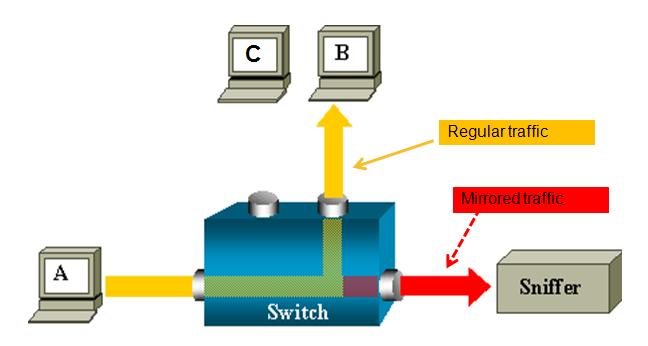
This document provides some extra documentation and use cases on the use of port spanning or port mirroring.
You can monitor traffic passing in & out of a set of L2 or L3 Ethernet interfaces (including bundle-Ether).
Core Issue
ASR 9000 is the only platform implementing SPAN on XR (Only support on ethernet linecards, not on SIP-700.)
You can use SPAN/Mirror in the follow scenarios
- L2 & L3 interfaces.
- Local, R-SPAN, and PW-SPAN only (no ER SPAN.)
- Scale limits:
8 monitor sessions
800 total source ports
1.5 Gig bidirectional replication limit toward fabric for bundle interfaces and 10 Gig ports.
Guideline: ~ 10% - 15% total bandwidth can be mirrored system-wide
- Source ports: Physical, EFPs, and bundles interfaces (L2 & L3)
- Destination ports: Ethernet interfaces, EFPs, and PW-SPAN. (No bundle) [ only L2 transport interfaces are supported as destination ports]
- Ability to use ACL's to define which traffic is to be captured
- Capture multicast traffic is possible
Note: some of the functionality mentioned are enhancements to the XR 4.0.1 release, this document assumes you are using this release or later.
A good reference on the terminology of SPAN/Mirror can be found here:
http://www.cisco.com/en/US/docs/switches/lan/catalyst6500/ios/12.2SX/configuration/guide/span.pdf
SPAN order of operation
SPAN mirrors what is on the wire
For ingress, this means packets are mirrored before QOS, ACL, and encapsulation rewrite operations.
For egress, this means packets are mirrored after QOS, ACL, and encapsulation rewrite operations.
Partial Packet Mirroring
User can configure to mirror first 64 upto 256 bytes of the packet.
Note: The actual mirrored packet will be the configured size plus 4-byte trailling CRC.
Sample config:
interface GigabitEthernet0/6/0/20 l2transport
monitor-session PW
mirror first 100 <== valid range: [64, 256], inclusively
!
!
Note: The mirrored packet received at sniffer will have the size of 104
(4-byte of trailing CRC added by transmit MAC layer.)
ACL based Mirroring
“permit/deny” determines the behavior of the regular traffic (forwarded or dropped)
“capture” determines whether the packet is mirrored to the SPAN destination.
On SPAN: mirror traffic on the wire (regardless with or without ACL.)
ACL on ingress direction:
SPAN will mirror traffic even regular traffic dropped by ACL: Always mirror!
ACL on egress direction
Will mirror if regular traffic is forwarded (Permit)
Will not mirror if regular traffic is dropped (Deny.)
Inconsistent configurations:
“acl” is configured on SPAN source port but
ACL has no “capture” keyword:
No traffic gets mirrored.
“acl” is NOT configured on SPAN source port but
ACL has “capture” keyword:
Mirroring traffic as normal, no ACL performed.
The ACL can also be an L2 ACL :
ethernet-services access-list esacl_t2
10 deny 1234.5678.90ab 0000.0000.0000 any capture
L3 Spanning Example
monitor-session TEST
destination interface GigabitEthernet0/1/0/2 (<<<< this is NP3)
!
interface GigabitEthernet0/1/0/14 (<<<< this is NP2)
ipv4 address 5.5.1.1 255.255.255.0
monitor-session TEST
acl
!
load-interval 30
ipv4 access-group span ingress
!
ipv4 access-list span
10 permit ipv4 any host 1.1.1.10 capture
15 permit ipv4 any host 239.1.1.1 capture
20 permit ipv4 any host 2.2.2.100
30 permit ipv4 any any
Sample TRAFFIC GEN: (sending multicast in this example)
tgn rate 1000
L2-dest-addr 0100.5E01.0101
L2-src-addr 0003.A0FD.28A8
L3-src-addr 5.5.1.2
L3-dest-addr 239.1.1.1
Checking NP2: (the port that we are spanning)
Show global stats counters for NP2, revision v3
Read 12 non-zero NP counters:
Offset Counter FrameValue Rate (pps)
-------------------------------------------------------------------------------
22 PARSE_ENET_RECEIVE_CNT 5478 1001
31 PARSE_INGRESS_DROP_CNT 3 1
33 RESOLVE_INGRESS_DROP_CNT 5474 1000
(there is no mcast recipient for this mcast addr, but we’re still replicating, see red line)
40 PARSE_INGRESS_PUNT_CNT 1 0
50 MODIFY_RX_SPAN_CNT 5475 1000
54 MODIFY_FRAMES_PADDED_CNT 5475 1000
68 RESOLVE_INGRESS_L3_PUNT_CNT 1 0
104 LOOP 1 0
224 PUNT_STATISTICS 9 2
480 RESOLVE_IPM4_ING_RTE_DROP_CNT 5475 1000
565 UIDB_TCAM_MISS_AGG_DROP 3 1
570 UIDB_TCAM_MISS_PORT4_DROP_FOR_HOST 3 0
NP3 is the span monitor interface:
Show global stats counters for NP3, revision v3
Read 16 non-zero NP counters:
Offset Counter FrameValue Rate (pps)
-------------------------------------------------------------------------------
22 PARSE_ENET_RECEIVE_CNT 36 0
23 PARSE_FABRIC_RECEIVE_CNT 79656 1000
30 MODIFY_ENET_TRANSMIT_CNT 79655 1000
Packets received from fabric and sent off to the Ethernet on the span port!
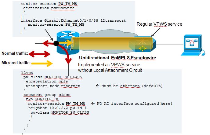
PW SPAN example
For PW span to work, you need to define a local monitor session with a destination pseudo wire. You apply that span session to the interface of interest and define an xconnect group that also leverages that span session as one of the pw ends.
On the remote side where the PW terminates, you just configure regular VPWS.
Here an example:
On the Local Side, besides my Span configuration, there is also a local cross connect between the interested session we want to span over the PW
l2vpn
xconnect group TEST
p2p TEST
interface GigabitEthernet0/1/0/39
! port 39 is the port where we apply the span on.
interface GigabitEthernet0/1/0/20.100
! this is just a random AC to have traffic flowing between the spanned port.
!
AC configuration:
interface GigabitEthernet0/1/0/20.100 l2transport
encapsulation dot1q 100
rewrite ingress tag pop 1 symmetric
! the tag is popped because the other XCON end is a plain ethernet without vlan. The explanation and use cases of tag popping can be found a related
! Tech note article.
Configuration on the remote side:
Regular VPWS configuration:
RP/0/RSP0/CPU0:A9K-TOP#sh run l2vpn
l2vpn
xconnect group PW-SPAN
p2p PW-SPAN_1
interface GigabitEthernet0/0/0/39
neighbor 2.2.2.2 pw-id 1
!
!
!
interface GigabitEthernet0/0/0/39
load-interval 30
transceiver permit pid all
l2transport
!
!
the neighbor in the l2vpn configuration is the LDP neighbor ID
between which the PW is built.
Show on remote side:
RP/0/RSP0/CPU0:A9K-TOP#show l2vpn xcon group PW-SPAN det
Group PW-SPAN, XC PW-SPAN_1, state is up; Interworking none
AC: GigabitEthernet0/0/0/39, state is up
Type Ethernet
MTU 1500; XC ID 0x4000a; interworking none
Statistics:
packets: received 0, sent 16570475
bytes: received 0, sent 994228500
! packets received from the PW are sent out hte Attachment circuit's interface. The analyzer is connected to G0/0/0/39
PW: neighbor 2.2.2.2, PW ID 1000, state is up ( established )
PW class not set, XC ID 0x4000a
Encapsulation MPLS, protocol LDP
PW type Ethernet, control word disabled, interworking none
PW backup disable delay 0 sec
Sequencing not set
MPLS Local Remote
------------ ------------------------------ -----------------------------
Label 16002 16027
Group ID 0xa40 0x2
Interface GigabitEthernet0/0/0/39 PW/TM/MS
MTU 1500 1500
Control word disabled disabled
PW type Ethernet Ethernet
VCCV CV type 0x2 0x2
(LSP ping verification) (LSP ping verification)
VCCV CC type 0x6 0x6
(router alert label) (router alert label)
(TTL expiry) (TTL expiry)
------------ ------------------------------ -----------------------------
MIB cpwVcIndex: 4294705162
Create time: 04/04/2011 14:36:42 (00:20:07 ago)
Last time status changed: 04/04/2011 14:36:42 (00:20:07 ago)
Statistics:
packets: received 16570475, sent 0
bytes: received 994228500, sent 0
! Packets received on the Pseudo Wire from the SPAN port
NOTE: Pseudo Wire counters on the span side are not incrementing.That is the XCON group "cisco" in this picture config example.
This is intentional. You can review the SPANNING also with this command:
RP/0/RSP1/CPU0:A9K-BOTTOM#sh monitor-session counters
Monitor-session PW_TM_MS
GigabitEthernet0/1/0/39
Rx replicated: 58488205 packets, 3743245120 octets
Tx replicated: 58488206 packets, 3743245184 octets
Non-replicated: 0 packets, 0 octets
R-SPAN configuration:
R-SPAN is natively support with the capability of ASR9000 to do vlan imposition:
monitor-session MS2
destination interface gig0/2/0/19.10
!
interface gig0/2/0/12.10 l2transport
encapsulation dot1q 10 <<< Monitoring vlan 10 traffic
monitor-session MS2
!
interface gig0/2/0/19.10 l2transport (*)
encapsulation dot1q 100 <<< VLAN 100 will get imposed.
!
(*) Monitor destination could be any supported destination interface regardless of monitor source
Related Information
n/a
Xander Thuijs, CCIE #6775
Sr. Tech Lead ASR9000
- Mark as Read
- Mark as New
- Bookmark
- Permalink
- Report Inappropriate Content
Hello
I am testing pw span between 2 asr9k, but i don't seem to get i t to work. I get the pw:s up, but i do not get any traffic at my sniffer. What config is supposed to be at the remote end? How do you map the pw to the physical interface the sniffer is located at? I must be thinking wrong here..
regards
Andreas
- Mark as Read
- Mark as New
- Bookmark
- Permalink
- Report Inappropriate Content
Andreas, I reviewed the configuration example I provided and I noticed a small but important issue there. The monitor span session NAME on the interface did not match the globally defined span monitor session name.
I revised the configuration example to be correct now and provided some sample outputs to verify the operation, with a config example for the remote side also. Hopefully this resolves your issue.
- Mark as Read
- Mark as New
- Bookmark
- Permalink
- Report Inappropriate Content
Thank you for clarification. I got the setup working now.
- Mark as Read
- Mark as New
- Bookmark
- Permalink
- Report Inappropriate Content
Thanks for the document.
I have a question Can I have tengig as source and 1 gig as destination ?
- Mark as Read
- Mark as New
- Bookmark
- Permalink
- Report Inappropriate Content
Hi Aravala,
sure thing you can, but if you'd have to span 2G worth of traffic out a 1G destination, obviously not everything will leave the interface.
xander
- Mark as Read
- Mark as New
- Bookmark
- Permalink
- Report Inappropriate Content
Hi Alexander,
I have two ports as a monitor port source
int ge 0/0/0/1.100 l2 transport ( l2 interface with vlans 100)
and
ge 0/0/0/2 ( l3 interface)
and monitor port destinnation interface ge 0/0/0/3
when I connect pc to destination port with wireshark - i can see only traffic from l2 interface ge 0/0/0/1.100.
Another question is if on destination port traffic is still encapsulated with 8021.q 100 ?
regards,
- Mark as Read
- Mark as New
- Bookmark
- Permalink
- Report Inappropriate Content
make sure that your g 0/0/0/3 (destination) interface is an l2transport interface.
your original l2 encap will be preserved.
and for the l3 interface did you apply an acl with the capture keyword?
xander
- Mark as Read
- Mark as New
- Bookmark
- Permalink
- Report Inappropriate Content
Hi Alexander,
i would like to know if i perform ingress packet capture whether we capture before or after traffic processed by NP? there are lot of packet drops occur on the particular NP so i want to know what kind of traffic are being drops.
another question: is input rate on show interface calculated before or after drops?
- Mark as Read
- Mark as New
- Bookmark
- Permalink
- Report Inappropriate Content
That should work no problem.
Note that the destinatoin port needs to be of the l2transport kind, so make sure that
"g0/0/0/3 l2trasnsport" exists.
Full heads will be preserved, mpls label and dot1q tags.
For the L3 spanning, you may need to configure an ACL with the capture keyword to identify the packets to be spanned. this ACE in the ACL can of course be a "ipv4 any any capture" kind to catch them all.
regards
xander
- Mark as Read
- Mark as New
- Bookmark
- Permalink
- Report Inappropriate Content
Hi Xander,
I don't found how to span RX and TX from same source interface to mirrored different destination interface, if you have some workaround on that, could you share with us ?
Source port : Te0/1/0/1 (both_rx_&_tx_)
Destination port1 : Te0/2/0/1 (rx_only)
Destination port2 : Te0/3/0/1 (tx_only)
I try to create 2 monitor-session but couldn't apply on the same interface ![]()
Thank you,
Hendro
- Mark as Read
- Mark as New
- Bookmark
- Permalink
- Report Inappropriate Content
Hi Hendro,
you cannot have 2 Montior sessions on one interface...the configs will override each other.
I do not see any workaround for this...
what is the reason for doing this though ? Is there any specific situation for wanting to do this ?
- Mark as Read
- Mark as New
- Bookmark
- Permalink
- Report Inappropriate Content
Hi Skondala,
I need to simulate some test with an analyzer devices, and that devices need to know/identify ingress and egress traffic in different port, (they can't analyze/differentiated if i send ingress & egress in the same port.
Another question: it's possible to send out traffic SPAN to another router through interface A and process with acl to filter base on source address than passing into interface B as nexthop ?
I already test but i see this drop on interface A
#sh controllers np counters np0 location 0/3/CPU0 | i DROP
Mon Jul 14 10:11:01.466 WIB
Offset Counter FrameValue Rate (pps)
-------------------------------------------------------------------------------
134 PARSE_DROP_IPV4_DISABLED 147 0
381 RSV_DROP_IN_L3_NOT_MYMAC 483426256 83026
(RSV_DROP_IN_L3_NOT_MYMAC Drop L3 Unicast frames dropped on layer3 ingress interface because they do not match the interface MAC address (packet not destined for this next-hop).)
Regards,
Hendro
- Mark as Read
- Mark as New
- Bookmark
- Permalink
- Report Inappropriate Content
yeah you could do that for instance by making interface A an l2transport interface.
then the path to "B" is also an l2transport interface and you put them both into an xconnect p2p group. On the l2transport interface-A side, you can apply an L3 ACL to do the filtering.
regards
xander
- Mark as Read
- Mark as New
- Bookmark
- Permalink
- Report Inappropriate Content
Hi Xander,
I have performance question about traffic mirroring capacity of enhanced ethernet line cards (2.gen typhoon). The doc says there is no bandwidth limitation but I want to be sure, as we are planning to use this feature on 10G bundles.
Thanks a lot.
- Mark as Read
- Mark as New
- Bookmark
- Permalink
- Report Inappropriate Content
that is correct Deniz. On trident we have a bw and pps limitation, but that bw limitation due to the higher capacity FIA and fabrics this problem does not exist with typhoon cards.
The pps limit obviously still exists to some extent: Every packet spanned is effectively a new packet handle. This means that with a typhoon capable of doing 45Mpps, if every packet is spanned you'll end up with 22.5Mpps usable pps performance.
cheers
xander
Find answers to your questions by entering keywords or phrases in the Search bar above. New here? Use these resources to familiarize yourself with the community: