- Cisco Community
- Technology and Support
- Service Providers
- Service Providers Knowledge Base
- ASR9000/XR: Understanding QOS, default marking behavior and troubleshooting
- Subscribe to RSS Feed
- Mark as New
- Mark as Read
- Bookmark
- Subscribe
- Printer Friendly Page
- Report Inappropriate Content
- Subscribe to RSS Feed
- Mark as New
- Mark as Read
- Bookmark
- Subscribe
- Printer Friendly Page
- Report Inappropriate Content
03-07-2011 01:43 PM - edited 12-18-2018 05:19 AM
Introduction
This document provides details on how QOS is implemented in the ASR9000 and how to interpret and troubleshoot qos related issues.
Core Issue
QOS is always a complex topic and with this article I'll try to describe the QOS architecture and provide some tips for troubleshooting.
Based on feedback on this document I'll keep enhancing it to document more things bsaed on that feedback.
The ASR9000 employs an end to end qos architecture throughout the whole system, what that means is that priority is propagated throughout the systems forwarding asics. This is done via backpressure between the different fowarding asics.
One very key aspect of the A9K's qos implementation is the concept of using VOQ's (virtual output queues). Each network processor, or in fact every 10G entity in the system is represented in the Fabric Interfacing ASIC (FIA) by a VOQ on each linecard.
That means in a fully loaded system with say 24 x 10G cards, each linecard having 8 NPU's and 4 FIA's, a total of 192 (24 times 8 slots) VOQ's are represented at each FIA of each linecard.
The VOQ's have 4 different priority levels: Priority 1, Priority 2, Default priority and multicast.
The different priority levels used are assigned on the packets fabric headers (internal headers) and can be set via QOS policy-maps (MQC; modular qos configuration).
When you define a policy-map and apply it to a (sub)interface, and in that policy map certain traffic is marked as priority level 1 or 2 the fabric headers will represent that also, so that this traffic is put in the higher priority queues of the forwarding asics as it traverses the FIA and fabric components.
If you dont apply any QOS configuration, all traffic is considered to be "default" in the fabric queues. In order to leverage the strength of the asr9000's asic priority levels, you will need to configure (ingress) QOS at the ports to apply the priority level desired.
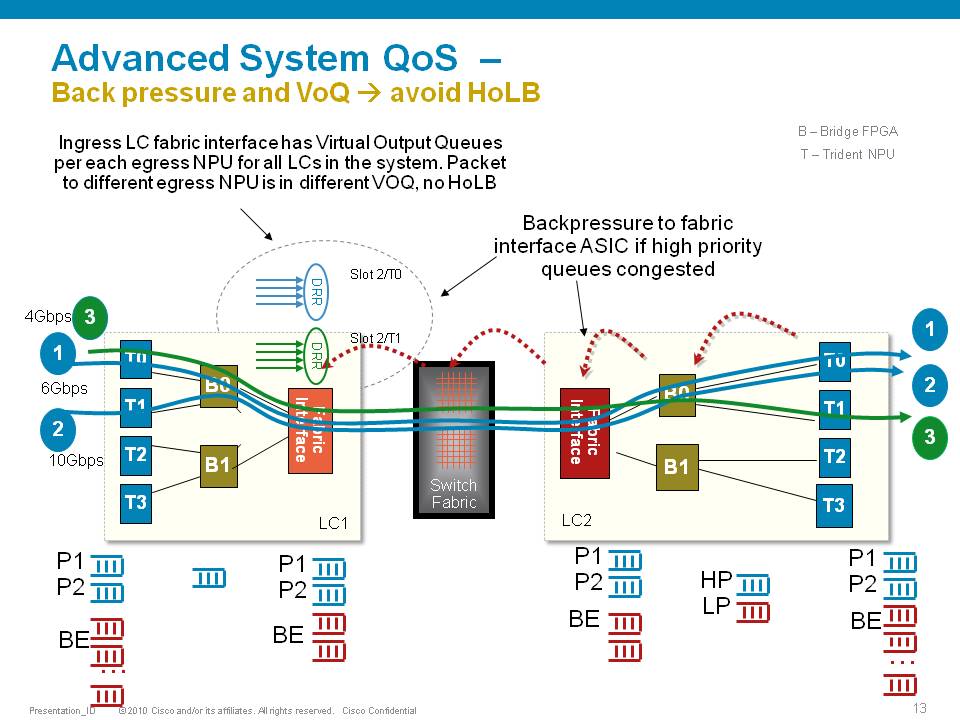
In this example T0 and T1 are receiving a total of 16G of traffic destined for T0 on the egress linecard. For a 10G port that is obviously too much.
T0 will flow off some of the traffic, depending on the queue, eventually signaling it back to the ingress linecard. While T0 on the ingress linecard also has some traffic for T1 on the egress LC (green), this traffic is not affected and continues to be sent to the destination port.
Resolution
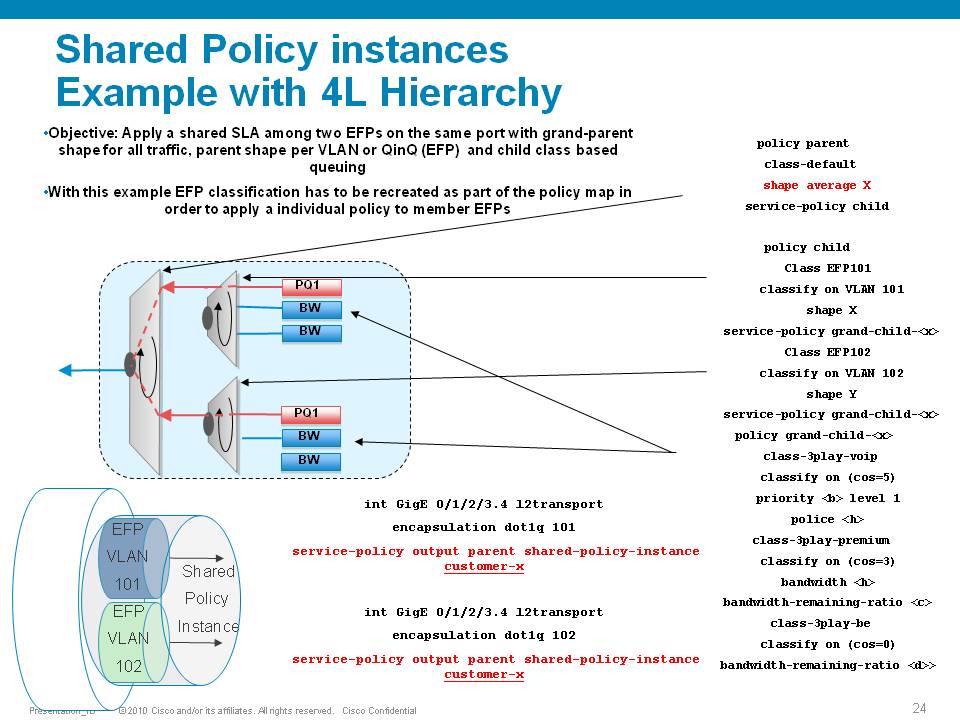
The ASR9000 has the ability of 4 levels of qos, a sample configuration and implemenation detail presented in this picture:
Policer having exceeddrops, not reaching configured rate
Set the Bc to CIR bps * (1 byte) / (8 bits) * 1.5 seconds
and
Be=2xBc
Default burst values are not optimal
Say you are allowing 1 pps, and then 1 second you don’t send anything, but the next second you want to send 2. in that second you’ll see an exceed, to visualize the problem.
Alternatively, Bc and Be can be configured in time units, e.g.:
policy-map OUT
class EF
police rate percent 25 burst 250 ms peak-burst 500 ms
For viewing the Bc and Be applied in hardware, run the "show qos interface interface [input|output]".
Why do I see non-zero values for Queue(conform) and Queue(exceed) in show policy-map commands?
On the ASR9k, every HW queue has a configured CIR and PIR value. These correspond to the "guaranteed" bandwidth for the queue, and the "maximum" bandwidth (aka shape rate) for the queue.
In some cases the user-defined QoS policy does NOT explicitly use both of these. However, depending on the exact QoS config the queueing hardware may require some nonzero value for these fields. Here, the system will choose a default value for the queue CIR. The "conform" counter in show policy-map is the number of packets/bytes that were transmitted within this CIR value, and the "exceed" value is the number of packets/bytes that were transmitted within the PIR value.
Note that "exceed" in this case does NOT equate to a packet drop, but rather a packet that is above the CIR rate on that queue.
You could change this behavior by explicitly configuring a bandwidth and/or a shape rate on each queue, but in general it's just easier to recognize that these counters don't apply to your specific situation and ignore them.
What is counted in QOS policers and shapers?
When we define a shaper in a qos pmap, the shaper takes the L2 header into consideration.
The shape rate defined of say 1Mbps would mean that if I have no dot1q or qinq, I can technically send more IP traffic then having a QIQ which has more L2 overhead. When I define a bandwidth statement in a class, same applies, also L2 is taken into consideration.
When defining a policer, it looks at L2 also.
In Ingress, for both policer & shaper, we use the incoming packet size (including the L2 header).
In order to account the L2 header in ingress shaper case, we have to use a TM overhead accounting feature, that will only let us add overhead in 4 byte granularity, which can cause a little inaccuracy.
In egress, for both policer & shaper we use the outgoing packet size (including the L2 header).
ASR9K Policer implementation supports 64Kbps granularity. When a rate specified is not a multiple of 64Kbps the rate would be rounded down to the next lower 64Kbps rate.
For policing, shaping, BW command for ingress/egress direction the following fields are included in the accounting.
|
MAC DA |
MAC SA |
EtherType |
VLANs.. |
L3 headers/payload |
CRC |
Port level shaping
Shaping action requires a queue on which the shaping is applied. This queue must be created by a child level policy. Typically shaper is applied at parent or grandparent level, to allow for differentiation between traffic classes within the shaper. If there is a need to apply a flat port-level shaper, a child policy should be configured with 100% bandwidth explicitly allocated to class-default.
Understanding show policy-map counters
QOS counters and show interface drops:
Policer counts are directly against the (sub)interface and will get reported on the "show interface" drops count.
The drop counts you see are an aggregate of what the NP has dropped (in most cases) as well as policer drops.
Packets that get dropped before the policer is aware of them are not accounted for by the policy-map policer drops but may
show under the show interface drops and can be seen via the show controllers np count command.
Policy-map queue drops are not reported on the subinterface drop counts.
The reason for that is that subinterfaces may share queues with each other or the main interface and therefore we don’t
have subinterface granularity for queue related drops.
Counters come from the show policy-map interface command
| Class name as per configuration | Class precedence6 | ||||||||
| Statistics for this class | Classification statistics (packets/bytes) (rate - kbps) | ||||||||
| Packets that were matched | Matched : 31583572/2021348608 764652 | ||||||||
| packets that were sent to the wire | Transmitted : Un-determined | ||||||||
| packets that were dropped for any reason in this class | Total Dropped : Un-determined | ||||||||
| Policing stats | Policing statistics (packets/bytes) (rate - kbps) | ||||||||
| Packets that were below the CIR rate | Policed(conform) : 31583572/2021348608 764652 | ||||||||
| Packets that fell into the 2nd bucket above CIR but < PIR | Policed(exceed) : 0/0 0 | ||||||||
| Packets that fell into the 3rd bucket above PIR | Policed(violate) : 0/0 0 | ||||||||
| Total packets that the policer dropped | Policed and dropped : 0/0 | ||||||||
| Statistics for Q'ing | Queueing statistics <<<---- | ||||||||
| Internal unique queue reference | Queue ID : 136 | ||||||||
|
how many packets were q'd/held at max one time (value not supported by HW) |
High watermark (Unknown) | ||||||||
|
number of 512-byte particles which are currently waiting in the queue |
Inst-queue-len (packets) : 4096 | ||||||||
|
how many packets on average we have to buffer (value not supported by HW) |
Avg-queue-len (Unknown) | ||||||||
|
packets that could not be buffered because we held more then the max length |
Taildropped(packets/bytes) : 31581615/2021223360 | ||||||||
| see description above (queue exceed section) | Queue(conform) : 31581358/2021206912 764652 | ||||||||
| see description above (queue exceed section) | Queue(exceed) : 0/0 0 | ||||||||
|
Packets subject to Randon Early detection and were dropped. |
RED random drops(packets/bytes) : 0/0 | ||||||||
Understanding the hardware qos output
RP/0/RSP0/CPU0:A9K-TOP#show qos interface g0/0/0/0 output
With this command the actual hardware programming can be verified of the qos policy on the interface
(not related to the output from the previous example above)
Tue Mar 8 16:46:21.167 UTC
Interface: GigabitEthernet0_0_0_0 output
Bandwidth configured: 1000000 kbps Bandwidth programed: 1000000
ANCP user configured: 0 kbps ANCP programed in HW: 0 kbps
Port Shaper programed in HW: 0 kbps
Policy: Egress102 Total number of classes: 2
----------------------------------------------------------------------
Level: 0 Policy: Egress102 Class: Qos-Group7
QueueID: 2 (Port Default)
Policer Profile: 31 (Single)
Conform: 100000 kbps (10 percent) Burst: 1248460 bytes (0 Default)
Child Policer Conform: TX
Child Policer Exceed: DROP
Child Policer Violate: DROP
----------------------------------------------------------------------
Level: 0 Policy: Egress102 Class: class-default
QueueID: 2 (Port Default)
----------------------------------------------------------------------
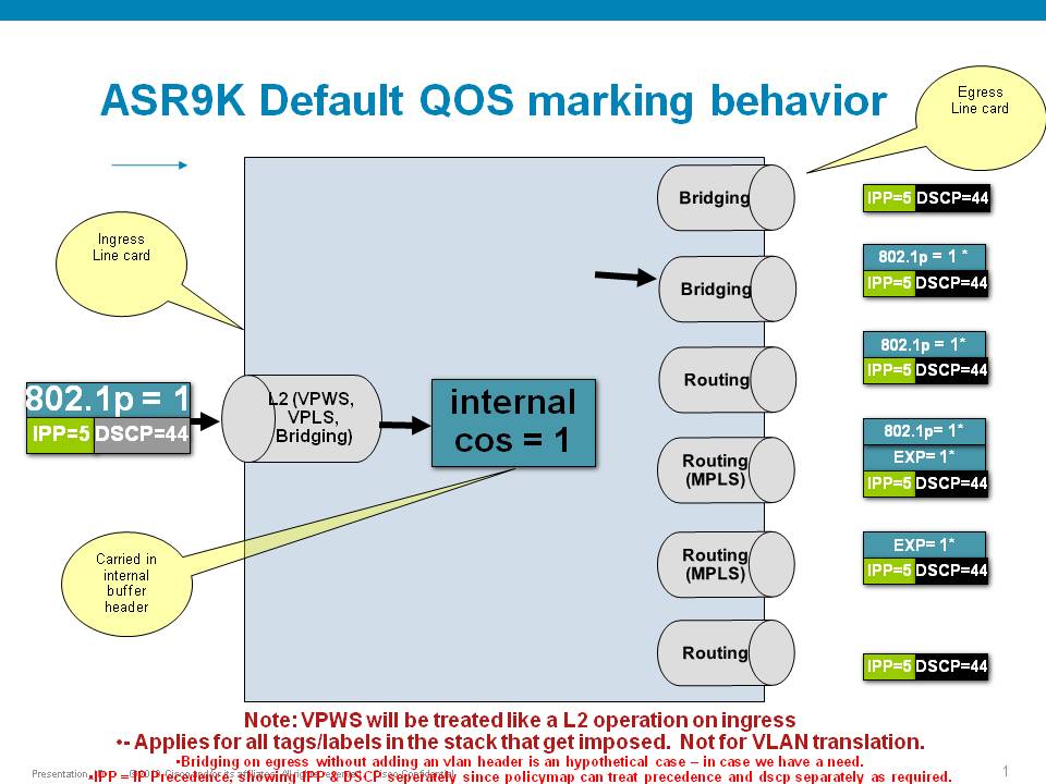
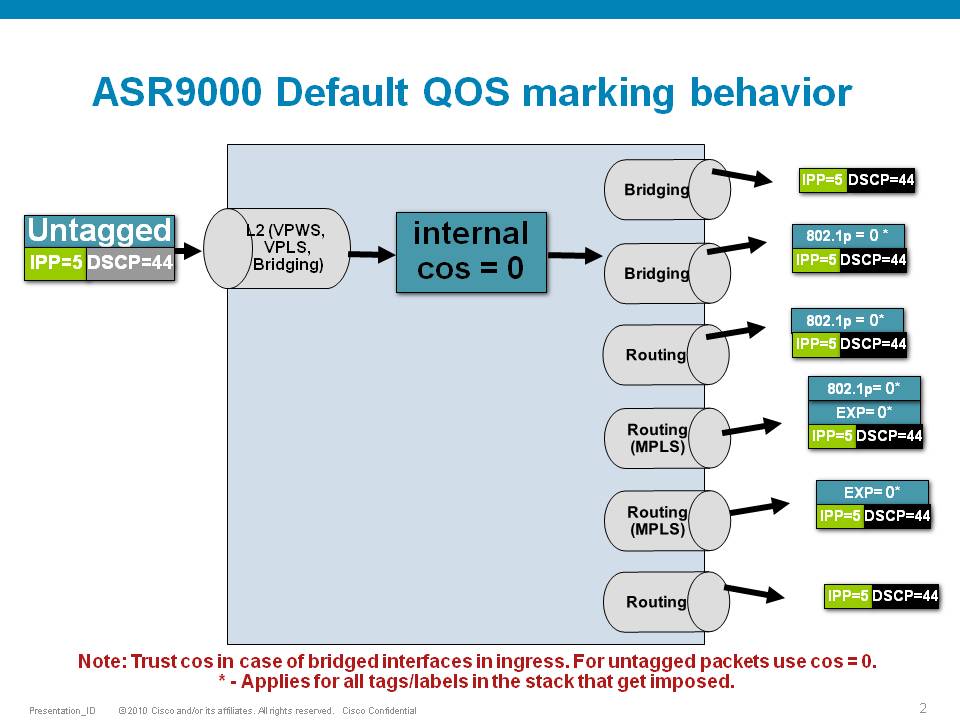
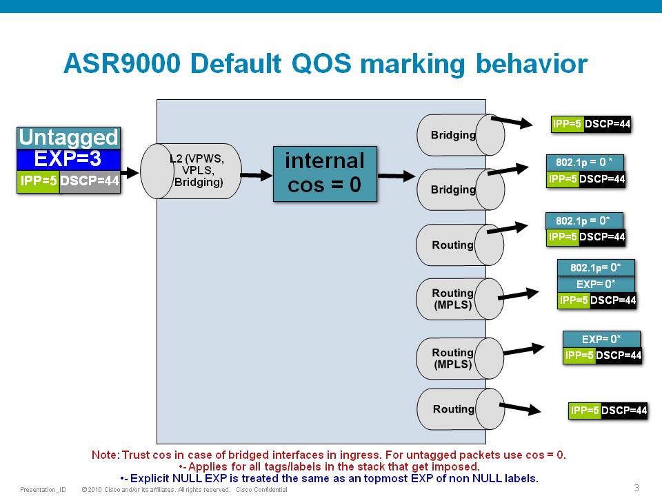
Default Marking behavior of the ASR9000
If you don't configure any service policies for QOS, the ASR9000 will set an internal cos value based on the IP Precedence, 802.1 Priority field or the mpls EXP bits.
Depending on the routing or switching scenario, this internal cos value will be used to do potential marking on newly imposed headers on egress.
Scenario 1
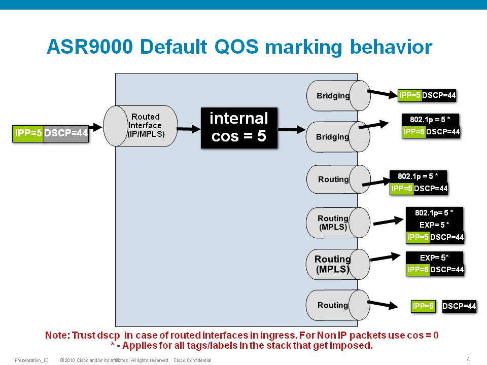
Scenario 2
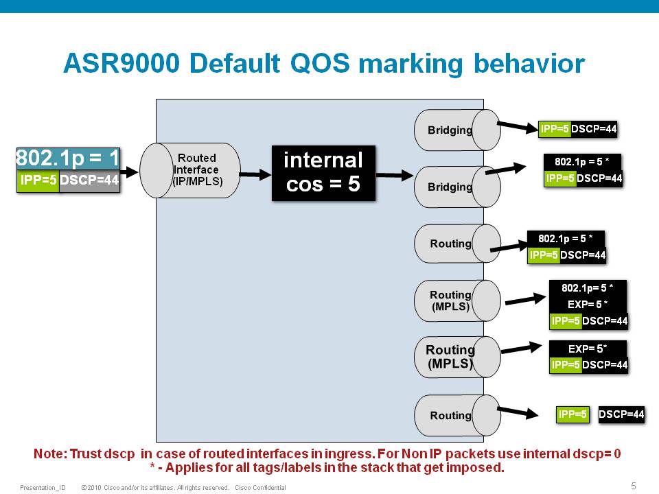
Scenario 3
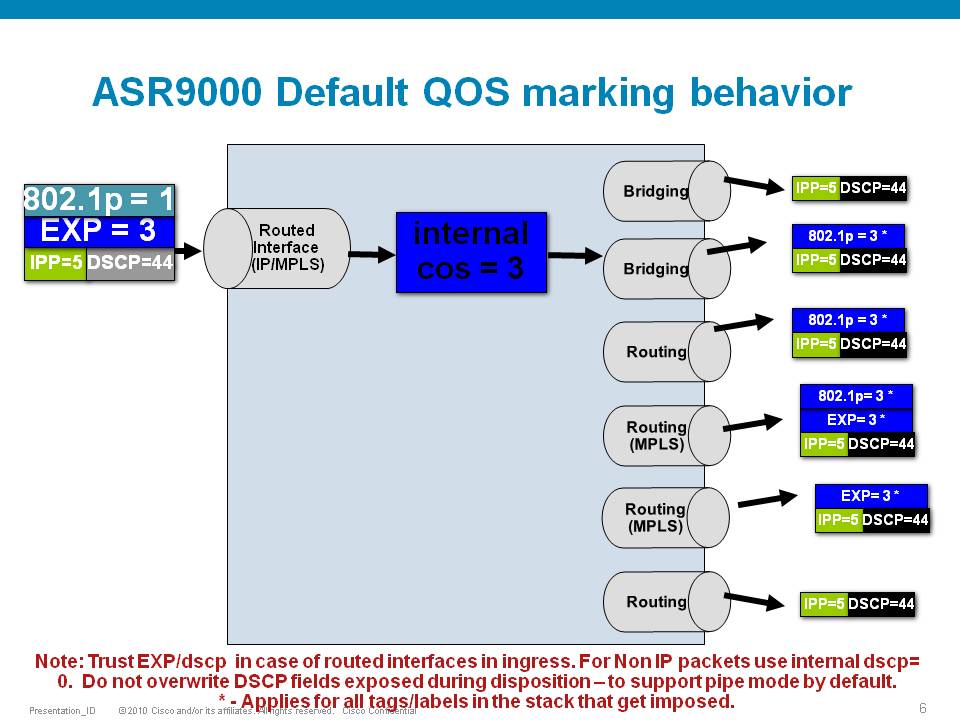
Scenario 4
Scenario 5
Scenario 6
Special consideration:
If the node is L3 forwarding, then there is no L2 CoS propagation or preservation as the L2 domain stops at the incoming interface and restarts at the outgoing interface.
Default marking PHB on L3 retains no L2 CoS information even if the incoming interface happened to be an 802.1q or 802.1ad/q-in-q sub interface.
CoS may appear to be propagated, if the corresponding L3 field (prec/dscp) used for default marking matches the incoming CoS value and so, is used as is for imposed L2 headers at egress.
If the node is L2 switching, then the incoming L2 header will be preserved unless the node has ingress or egress rewrites configured on the EFPs.
If an L2 rewrite results in new header imposition, then the default marking derived from the 3-bit PCP (as specified in 802.1p) on the incoming EFP is used to mark the new headers.
An exception to the above is that the DEI bit value from incoming 802.1ad / 802.1ah headers is propagated to imposed or topmost 802.1ad / 802.1ah headers for both L3 and L2 forwarding;
Related Information
ASR9000 Quality of Service configuration guide
Xander Thuijs, CCIE #6775
- Mark as Read
- Mark as New
- Bookmark
- Permalink
- Report Inappropriate Content
Great read! I do have a question though. We have a scenario where we use a 3rd Party Carrier/EVPL to connect hundreds of multi tenant CEs back to a single physical circuit on our PEs. It's very common for us to have 200-300+ EVCs on a single physical interface supporting multiple customer VRFs at a wide range of bandwidths from 5mbps to 1Gbps. My goal was to create a standard QOS policy that shapes outbound toward the CEs based on the configured bandwidth of the sub-interface. This worked great with the bandwidth QoS-reference command on the 7600 platform but doesn't work on the ASR 9ks.
Any thoughts on how to tackle this on the 9ks?
- Mark as Read
- Mark as New
- Bookmark
- Permalink
- Report Inappropriate Content
thank you salvatore! in a9k, you will need to define a parent shaper to shape the circuit.
you can use the bw percent in teh child classes to take a percentage of that parent shape rate.
policy-map PARENT
class class-default
shape av <rate>
service-policy CHILD
The child definition looking like:
policy-map CHILD
class VOICE
priority level 1
police rate percent X
class DATA
bandwidth percent Y
class class-default etc
cheers!
xander
- Mark as Read
- Mark as New
- Bookmark
- Permalink
- Report Inappropriate Content
Hi Xander,
See below. The issue is I can't shape based on the parent interface since it's variable. I have a 10Gig circuit but only allocating around 2-3Gbps across 100-150 sub-interfaces. Each sub-interface has an non standard bandwidth allocation based on the CE's needs. The customer at each site pretty much dictates the BW. We also have a 4 class QoS system that needs to be enforced on each sub-interfaces for Voip, TCP, UDP, and Best effort.
Te0/2/0/0 - Carrier EVPL CIRCUIT
Te0/2/0/0.10 - CE1 - 5Mbps
Te0/2/0/0.20 - CE 2 - 25Mbps
Te0/2/0/0.30 - CE 3 - 100Mbps
Te0/2/0/0.40 - CE4 - 500 Mbps
Te0/2/0/0.50 - CE5 - 50 Mbps
Te0/2/0/0.XXX - CE X - XXXMbps
 - Emeritus")
- Mark as Read
- Mark as New
- Bookmark
- Permalink
- Report Inappropriate Content
hi Salvatore,
have you considered configuring a hierarchical QoS policy where at the parent level you have a shaper and at child level the 4 QoS classes.
policy-map Parent_FA_Egress
class class-default
service-policy Child_FA_Egress
shape average 10 mbps
!
end-policy-map
!
policy-map Child_FA_Egress
<...>
This would be the cleanest solution on any platform.
/Aleksandar
- Mark as Read
- Mark as New
- Bookmark
- Permalink
- Report Inappropriate Content
correct that is what I meant to suggest. with parent shaper, I meant the hierarchical pmap with a parent shape and child subclasses. I think you may have thought I meant a shaping pmap on the main/parent interface, but that is not easy to manage.
You'd need a single child class with percentages and a few parent pmaps leveraging that child policy and the different designated shape rates needed.
Based on the vlan/subinterface, you apply that parent pmap to that intf.
cheers
xander
- Mark as Read
- Mark as New
- Bookmark
- Permalink
- Report Inappropriate Content
Thanks guys! This is kind of what I was expecting to hear. I'm still going to have to manage roughly 30-40 different parent pmaps due to the way we've done business over the years. Not ideal and hopefully over time we'll reduce these down to a handful of standard BW offerings.
- Mark as Read
- Mark as New
- Bookmark
- Permalink
- Report Inappropriate Content
Hi Xander,
Thanks for the info, its always spot on. I do have a clarification question regarding the default behavior. If I don't apply any QOS configuration at all then the router will use the default marking behavior, correct? I am currently in a scenario where the CPE is marking COS but I don't have any QOS configured in my ASR9010 and I want to make sure I understand what the device will do with the marked traffic.
Regards,
Dan
- Mark as Read
- Mark as New
- Bookmark
- Permalink
- Report Inappropriate Content
correct Dan! and thanks :) yeah the markings from the CPE will be taken as is and converted into the internal "cos" to be used for mpls EXP, dot1p COS etc. So if you don't "trust" the cPE's marking, then you will want to use an ingress policy to remark and make sure the right core header prioritization is set for, otherwise a CPE may send its stuff with good markings, abusing your core policies!
xander
- Mark as Read
- Mark as New
- Bookmark
- Permalink
- Report Inappropriate Content
Great information, Xander. I was hoping you could help clarify a couple points on physical memory buffers on the ASR9K.
As you pointed out in this document, the ASR9K uses a VoQ queuing mechanism. Other vendor platforms that use VoQ's buffer on the ingress line-card, and the egress line-card simply "pull" the traffic from the ingress line-card. With this architecture, the ingress line-card is where all of the physical buffer memory is located. In your document, you seem to mention that back-pressure is only applied on the ingress line-card in the case of congestion. With that notion, it would seem that it's possible that the egress line-card would also have buffer memory. I've also heard from our own Cisco team that the ASR9K uses a two-stage buffering system. Can you help clarify where exactly the packets are buffered during both normal forwarding without congestion, as well as times when there is congestion? Does the ASR9K also "pull" traffic from the ingress line-card?
Thank you.
- Mark as Read
- Mark as New
- Bookmark
- Permalink
- Report Inappropriate Content
packet forwarding through ASR9k (including the way that back-pressure works) are explained in Cisco Live BRKARC-2003 and BRKSPG-2904 from San Diego, Milan or Berlin.
In short, if you disregard the packet buffering while the NP is actually processing the packet to make the forwarding decision, packet buffering can happen on the ingress NP (if it supports ingress queuing and you choose to configure it), ingress FIA (in case of back-pressure from the egress FIA), egress FIA (in case of back-pressure from egress NP) and on the egress NP.
- Mark as Read
- Mark as New
- Bookmark
- Permalink
- Report Inappropriate Content
Doing buffering only on ingress LCs and having egress LCs pulling traffic is possible only when each VOQ(on ingress) represents exactly one particular egress queue.
However such an architecture is possible/scales only on platforms with fixed and limited number of egress queues, say 8 per port (and no HQoS/shaping on egress). Only in such a system the backpressure mechanism is granular enough that the egress LC can pull from a given ingress VOQ exactly what it can transmit out via a particular egress queue. So what it’ll receive it can transmit right away thus no need for buffering.
As Xander mentioned that’s not the entire truth though, as even on such a platform you still need some “in-flight” buffer on egress where the packet bodies are buffered while the heads are being processed by the PPEs in NP.
On tomahawk cards you can go up to 1M queues if I remember correctly so such architecture would not scale (can’t imagine the fabric scheduler algorithm doing maximal match for 1M*#of ports in chassis at such high BW rates).
Thus on platforms with advanced queuing you still need some delay BW buffer on egress LCs.
So the egress PFE just pulls whatever the egress port or 10GE entity should be able to transmit, but since you have multiple VLANs on that port each shaped to some BW the excess (i.e. what can’t be TX-ed out the port due to the various shapings) is going to be buffered in egress delay bw buffers.
The "VOQ" on ingress module represents BW* capacity of an egress entity**.
And for the above to hold true the system has to run arbitration - and that in turn results in implicit*** back-pressure.
*in correct implementations it should actually represent processing capacity per egress entity which then results in BW capacity as at the end of the day we still need to transport the whole packet body across the system.
**the egress entity could be: a queue, a BW entity (e.g. a 10Gbps entity on a 100GE int with a 10GE breakout cable), a port, a PFE/NPU, a LC.
***implicit back-pressure means the back-pressure is realized as a result of granting access only for what can be processed(and transmitted) per the egress entity.
(examples of such a system with different granularity are: MX, QFX, PTX, ASR9K, NCS6K)
In contrast to the above would be a system using destination queues on ingress (i.e. not VOQs) and egress speedup
Speedup and buffers at egress module (and fabric) are just right to keep the contention until egress module can propagate backpressure signal* to ingress module - that is until the backpressure signal is propagated from egress module towards the ingress modules that then slows down the rate at which they transmit to fabric and will then start buffering (on egress to fabric).
And there on ingress module I can have per-entity “destination queues” not called VOQs however cause they don’t represent potential BW capacity on egress.
*explicit backpressure, i.e. the ingress module slows down as a result of receiving a “slowdown message” from egress module.
(an example of such a system would be Cisco CRS1 and 3)
At least that’s my understanding.
@Xander, did I get it right please?
- Mark as Read
- Mark as New
- Bookmark
- Permalink
- Report Inappropriate Content
Let me try to see if I can clarify a few things:
If you assume a simplified forwarding model of: /--if(y)
ingress NP---Ingress FIA---<FABRIC>---egress FIA(1)----egress NPU(1)---if(x)
\--------egress FIA(2)----egress NPU(2)
- the VOQ's live on the FIA.
- There are 4 VQI's in that VOQ: pri1/pri2/default/mcast
- a VOQ (in typhoon) represents an egress 10G entity
- If say intf(x) is overloaded, it will send a back pressure to the FIA's to ask it to hold off on sending default class traffic for that intf.
- meaning ingress FIA wil continue to send to intf(y) and NPU(2).
- this VOQ default class does NOT take any bw configs into cosnideration.anything that is not marked on ingress as p1/p2 or is mcast will go into that class-default of the voq.
- the FIA has buffering available.
There is also buffering capable on the NPU's in terms of a qos/mqc configuration.
buffering will happen when a shaped class is used or a parent shaper.
this buffering or capability needs to be configured with a pmap and is irrespective of the FIA buffering that happens when backpressure is exerted.
cheers!
xander
- Mark as Read
- Mark as New
- Bookmark
- Permalink
- Report Inappropriate Content
Thanks, Xander. I'm going to process over what you said and think about this some more. One more point to clarify: Cisco presents multiple buffer sizes depending on line-card type. For example, the Typhoon "TR" type cards, it lists either 113ms of buffering or 170ms of buffering, depending on the number of output 10GE ports. Where exactly is this buffering being measured? On the NP?
Thanks!
- Mark as Read
- Mark as New
- Bookmark
- Permalink
- Report Inappropriate Content
Sorry, Xander. Ignore my last question. I forgot about this document and that you already answered this question:
https://supportforums.cisco.com/document/143011/understanding-cisco-asr-9000-series-aggregation-services-routers-platform#Q._What_is_the_default_queue_buffer_size
- Mark as Read
- Mark as New
- Bookmark
- Permalink
- Report Inappropriate Content
ah yeah but that one is for the trident linecards. typhoon has 1G (TR) and 2G (SE) available.
this size @ a particular rate equals time.
while you can configure the buffer in msec, packets and other quantities, in the end of the day it is converted to a space size under the hood.
show qos int <int> <dir> will show what is actually programmed for the hw.
cheers
xander
Find answers to your questions by entering keywords or phrases in the Search bar above. New here? Use these resources to familiarize yourself with the community: