- Cisco Community
- Technology and Support
- Data Center and Cloud
- Application Centric Infrastructure
- ACI Service Graph with F5 Load-Balancer
- Subscribe to RSS Feed
- Mark Topic as New
- Mark Topic as Read
- Float this Topic for Current User
- Bookmark
- Subscribe
- Mute
- Printer Friendly Page
- Mark as New
- Bookmark
- Subscribe
- Mute
- Subscribe to RSS Feed
- Permalink
- Report Inappropriate Content
04-14-2022 02:23 PM - edited 04-14-2022 02:31 PM
We are running into an issue with migrating our current F5 load-balancer from a legacy 7K routed network, to an ACI fabric. The F5 load-balancer is a Layer 3 router between our FrontEnd (LB-FE) and BackEnd (LB-BE) VLANs. We also have other servers on the LB-FE network that need to communicate directly to the pool members on the LB-BE network. This requires routing through the F5 with no NAT. The VIPs for load-balanced applications use the LB-FE network, and access to these services work properly. However, the systems that need to communicate directly to the systems on the LB-BE network are unable to establish a connection. I have confirmed the packets never make it to the F5 to be routed to the LB-BE network.

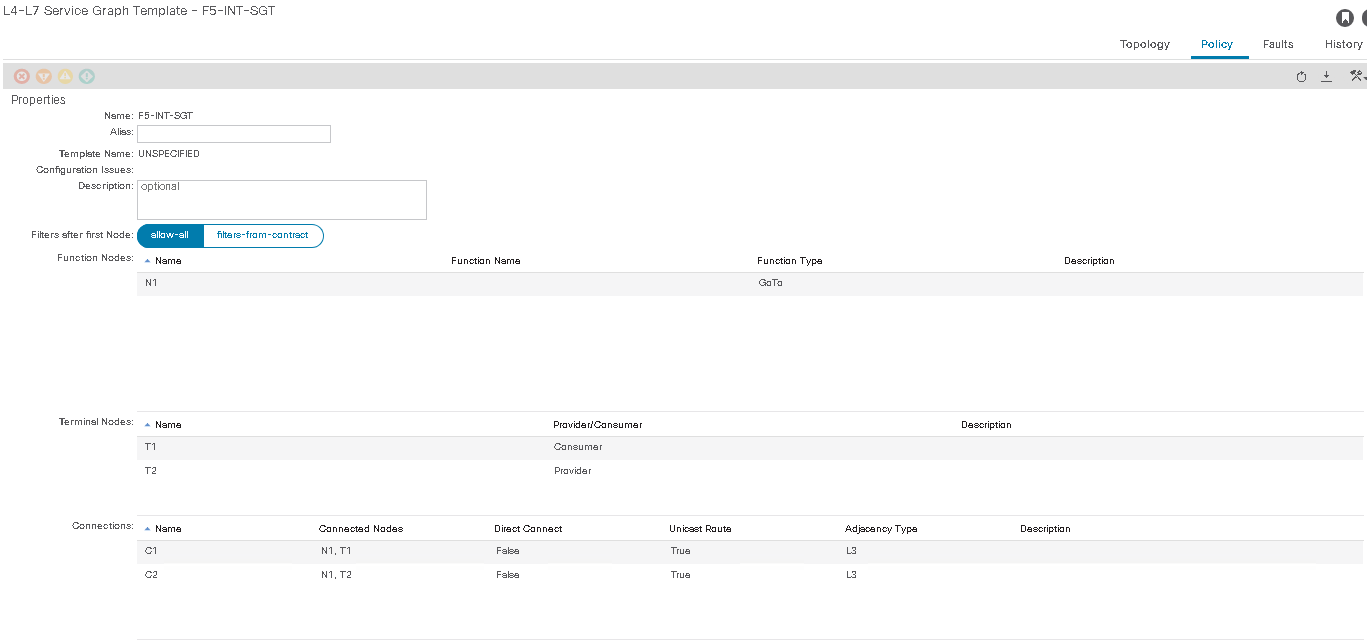
I have the F5 defined as a physical L4-L7 device with both the FrontEnd and BackEnd devices. I have an L4-L7 Policy-Based Redirect configured with the Self IP and MAC of the LB-FE interface. I also have the Service Graph Template setup for Two-Arm route-redirect and GoTo function Type. I have applied the Service Graph Template with a basic contract that allows all. The LB-FE EPG is the contract consumer and the LB-BE is the contract provider.
Both BDs and EPGs exist in the same VRF and Tenant. The LB-FE BD is configured with a subnet and is advertised out an L3Out. The LB-BE BD is not configured with a subnet or gateway. The F5 LB-BE interface is the gateway for the servers on the backend network.
I am not sure what I am missing, but I've reviewed all the ACI Service Graph configuration guides and examples I could find. Also, based on the topology examples in the Cisco Application Centric Infrastructure Policy-Based Redirect Service Graph Design White Paper , this should be a supported topology.
The Deployed Graph Instances branch shows that the Service Graph was successfully applied and there are not faults. I am not sure why I am unable to route through the F5 directly to the backend node.
F5 FrontEnd
BD: LB-FE_BD
EPG: LB-FE_EPG
Subnet: 10.10.100.0/24
Subnet GW: 10.10.100.1
F5 SelfIP: 10.10.100.2
Application VIP: 10.10.100.30
Contract: F5-LB-CONTRACT (Consumer)
F5 BackEnd
BD: LB-BE_BD
EPG: LB-BE_EPG
Subnet: 10.10.110.0/24
F5 SelfIP: 10.10.110.1
Application Pool Member IP: 10.10.110.30
Contract: F5-LB-CONTRACT (Provider)
Thanks in advance for any help.
Brian
Solved! Go to Solution.
- Labels:
-
APIC
-
Cisco ACI
-
Other ACI Topics
Accepted Solutions

")
- Mark as New
- Bookmark
- Subscribe
- Mute
- Subscribe to RSS Feed
- Permalink
- Report Inappropriate Content
06-09-2022 06:30 AM
Just to make sure I understand correctly your diagram:
- LB_BE bridge domain is just layer 2 in ACI and the gateway of the server pool is on the F5?
- What you want to achieve is to be able to access the BE subnet (the server pool) through both VIP and directly, right?
If the answer is YES to both questions, then you have two options to move forward:
1. Static routes under EPG:
- you basically just need to configure static LB-BE host routes (/32) inside the LB-FE EPG, with next hop 10.10.100.2.
Here is an example for the IP from your diagram:

Pros: you don't have to change the design;
Cons: you will have to configure a route for each endpoint in LB-BE
2. PBR
- for this to work, you need to move the GW of LB-BE to ACI
- remove interface to F5's FE & BE interfaces from the standard EPG and configure it as a service node
- configure PBR contract between the BE EPG and any other EPG you want to redirect the return traffic to F5.
Like this: https://www.cisco.com/c/en/us/solutions/collateral/data-center-virtualization/application-centric-infrastructure/white-paper-c11-739971.html#Deploymentoptions "Unidirectional PBR for load balancer without source NAT"
Pros: clean design
Cons: "advanced" knowledge is required for OAM & troubleshooting.
3. Redesign the topology:
- change the LB-FE BD to L2 and move the GW on F5
- configure a new L3Out interconnect between ACI and F5 with routes for both FE and BE pointing out to F5 and default route on F5 back to ACI.
Pros: both BE and FE are local to F5.
Cons: redesign
Out of these, there is no good or bad solution. Just one that works better for you and your team.
Hope it helps,
Sergiu
- Mark as New
- Bookmark
- Subscribe
- Mute
- Subscribe to RSS Feed
- Permalink
- Report Inappropriate Content
04-21-2022 12:29 AM
Hi @bburns2
Technically speaking you do not really need a PBR here. Communication from L3Out will be routed to F5 VIP and the return traffic will go to the F5 self_ip which I presume is the gateway for the server_pool.
In other words you do not really need the service graph here.
However, using the cfg as it is, I believe the problem you have there now is due to VIP option not being selected for FE_BE connector OR direct connect option set to False.
Take care,
Sergiu
- Mark as New
- Bookmark
- Subscribe
- Mute
- Subscribe to RSS Feed
- Permalink
- Report Inappropriate Content
04-26-2022 11:27 AM
Thanks Sergiu,
So if I wanted to accomplish this without a PBR, I would configure an L3Out to the F5 FrontEnd SelfIP to route to the BackEnd EPG? The problem I have with this is ACI does not allow me to configure an L3Out and an application EPG with the same VLAN encapsulation. I have servers on the same subnet as the F5 FrontEnd SelfIP. Also, I have a lot of application VIPs on the same FrontEnd subnet.
Thanks,
Brian
- Mark as New
- Bookmark
- Subscribe
- Mute
- Subscribe to RSS Feed
- Permalink
- Report Inappropriate Content
04-26-2022 10:10 PM
You don't need L3Out to F5 FE. Just a simple BD/EPG.
- Mark as New
- Bookmark
- Subscribe
- Mute
- Subscribe to RSS Feed
- Permalink
- Report Inappropriate Content
06-08-2022 11:49 AM
Thanks Sergiu,
Thanks for all the great help. I guess I am a little confused. If the backend BD/EPG is behind the F5 how do I route other BD/EPGs in the same VRF through the F5 load-balancer when it is acting as a layer 3 router with no NAT. I thought the only way to do this is with an L3Out or a Service Graph. If this were an NX-OS, I would simply put an ip route 10.10.110.0/24 10.10.100.2 in the VRF and redistribute the route to the firewall.
For example, in the updated diagram below, I have 3 BD/EPGs. One is the F5 FrontEnd and another is the F5 BackEnd. The third BD/EPG is for servers and other services (I actually have a lot more, but I am trying to simplify the scenario). I am able to forward traffic from the FrontEnd BD/EPG (10.10.100.0/24) to the BackEnd BD/EPG (10.10.110.0/24) through the F5 with a service graph, but I am unable to route the VLAN120 BD/EPG (10.20.100.0/24) to the BackEnd through the F5 FrontEnd SelfIP (Layer 3 routed with no NAT).

Thanks,
Brian
- Mark as New
- Bookmark
- Subscribe
- Mute
- Subscribe to RSS Feed
- Permalink
- Report Inappropriate Content
06-09-2022 06:30 AM
Just to make sure I understand correctly your diagram:
- LB_BE bridge domain is just layer 2 in ACI and the gateway of the server pool is on the F5?
- What you want to achieve is to be able to access the BE subnet (the server pool) through both VIP and directly, right?
If the answer is YES to both questions, then you have two options to move forward:
1. Static routes under EPG:
- you basically just need to configure static LB-BE host routes (/32) inside the LB-FE EPG, with next hop 10.10.100.2.
Here is an example for the IP from your diagram:
Pros: you don't have to change the design;
Cons: you will have to configure a route for each endpoint in LB-BE
2. PBR
- for this to work, you need to move the GW of LB-BE to ACI
- remove interface to F5's FE & BE interfaces from the standard EPG and configure it as a service node
- configure PBR contract between the BE EPG and any other EPG you want to redirect the return traffic to F5.
Like this: https://www.cisco.com/c/en/us/solutions/collateral/data-center-virtualization/application-centric-infrastructure/white-paper-c11-739971.html#Deploymentoptions "Unidirectional PBR for load balancer without source NAT"
Pros: clean design
Cons: "advanced" knowledge is required for OAM & troubleshooting.
3. Redesign the topology:
- change the LB-FE BD to L2 and move the GW on F5
- configure a new L3Out interconnect between ACI and F5 with routes for both FE and BE pointing out to F5 and default route on F5 back to ACI.
Pros: both BE and FE are local to F5.
Cons: redesign
Out of these, there is no good or bad solution. Just one that works better for you and your team.
Hope it helps,
Sergiu
- Mark as New
- Bookmark
- Subscribe
- Mute
- Subscribe to RSS Feed
- Permalink
- Report Inappropriate Content
06-10-2022 12:06 PM
Thanks for all the great information!
Yes, the LB_BE is just L2 in ACI. The gateway of the LB_BE server pool is the F5 BE SelfIP.
Yes, I need to be able to access the BE subnet through both the VIP and directly.
Based on the information you provided, I am considering #2 and #3. Option #2 should scale well with automation, but Option #3 will allow us to use the F5 health route injection to move VIPs between data centers and advertise the host routes to the WAN.
Thanks again for all the great information! This really helps me wrap my mind around moving from legacy routing and switching to ACI.
Brian
Discover and save your favorite ideas. Come back to expert answers, step-by-step guides, recent topics, and more.
New here? Get started with these tips. How to use Community New member guide
