Turn on suggestions
Auto-suggest helps you quickly narrow down your search results by suggesting possible matches as you type.
Showing results for
- Cisco Community
- Technology and Support
- Data Center and Cloud
- Data Center and Cloud Blogs
- Chalk Talk: The Top 5 Differences between Physical and Virtual Networking
10719
Views
5
Helpful
0
Comments
Options
- Subscribe to RSS Feed
- Mark as New
- Mark as Read
- Bookmark
- Subscribe
- Printer Friendly Page
- Report Inappropriate Content
07-18-2013
05:12 AM
With the ingenious creation of the Virtual Switch (or simply, vSwitch) at the beginning of the 2000s, VMware has introduced a new field of networking whose main responsibility is to handle virtual machine traffic within the realms of a hypervisor. Like any virtualization technology, virtual networking sustains the illusion of network devices with relative transparency while leveraging several processes from more than 30 years of networking history.
As server virtualization quickly dominated most data centers in the subsequent years, network professionals were introduced to virtual switches through its similarities with physical devices. But contrarily to The Matrix´s Neo, these technicians are usually required to swallow both blue (virtual) and red (physical) pills. And even with physical and virtual networks being brought closer to each other with the Cisco Nexus 1000V, I have seen many experienced network admins struggling to apply best-known practices from one world to another.
In my book, “Data Center Virtualization Fundamentals”, I have demonstrated how understanding the distinctions between virtual and physical elements can help unlock the potential of a virtualization technique in a Data Center. Following this method, this article will detail five conceptual differences between physical and virtual networking that can help you to better design and support server virtualization environments.
Difference #1: Network Policy Belongs to the Virtual Machine´s Virtual Network Interface Card
In physical networks, server access policies, which usually contain elements such as VLANs and ACLs, are directly configured on switch interfaces. On the other hand, virtual network access policies are bound to a VM´s virtual network interface card (or vnic, using the common language known as VMwarese).
This distinction is further detailed in Figure 1, which compares physical and virtual server migrations happening between modules on a chassis switch and on Nexus 1000V.
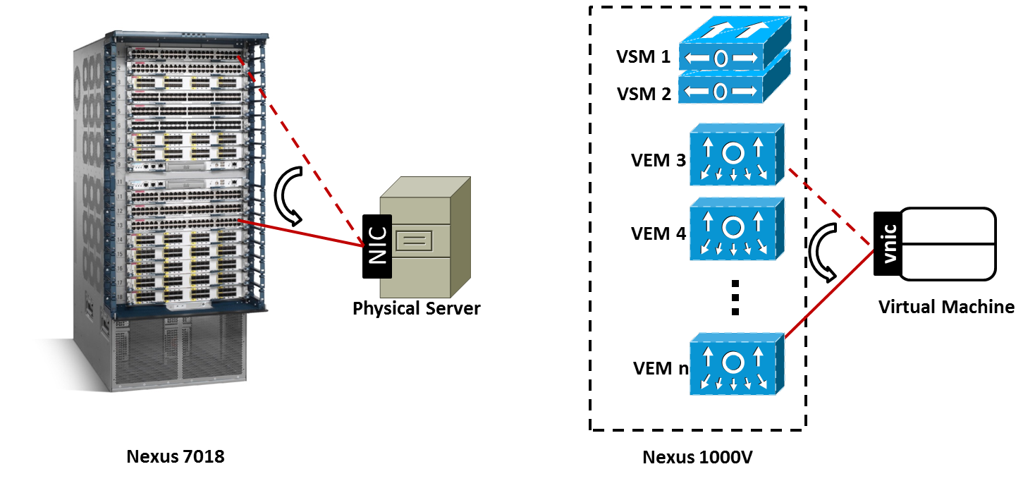
Figure 1: Comparing Server Migrations
A physical server migration can be thought as the disconnection of a server NIC from an interface on a chassis switch and reconnection on another module of the same switch (for example, from interface Ethernet 1/3 to Ethernet 11/45 on a Nexus 7018). In this case, to maintain connectivity and access policy enforcement, the network admin must configure the new interface with the same parameters from the previous port.
Nevertheless, on a VM online migration (also known as vMotion), the network access policy is linked to the vnic, wherever it may roam. Therefore, when a machine is changing hosts (and consequently, Virtual Ethernet Modules [VEMs] on a Nexus 1000V virtual chassis), no manual configuration is required from a network administration perspective. Actually, to facilitate the monitoring of VM traffic, Nexus 1000V assigns the same interface identifier (vEthernet25, for example) to the newly provisioned virtual interface in the destination VEM.
Without a doubt, this characteristic greatly reduces the amount of work that is expected from someone who is controlling thousands of access interfaces for virtual machines.
Difference #2: Virtual Network Interface Card MAC Address Table Entries Are Static
A virtual switch such as Nexus 1000V does not require MAC address learning in virtual Ethernet interfaces. In fact, because of the management connection between Nexus 1000V and VM managers (such as VMware vCenter and Microsoft SCVMM), Nexus 1000V uses the addresses assigned by the VM manager in the VM creation to populate its MAC address table.
Table 1 exhibits this distinction:
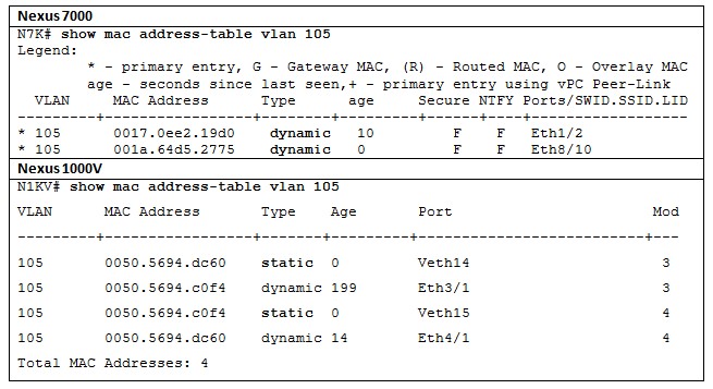
Both command outputs show how each switch detects two servers connected to different modules. While the physical switch (N7K) learns the MAC address through traffic sent by the servers to interfaces Ethernet1/2 and 8/10, N1KV assigns a static entry for each VM in its corresponding module.
Table 1 depicts yet another difference between both devices: in Nexus 1000V, each VEM truly acts as an independent switch. As you can see, VEM 3 has dynamically learned MAC address 0050.5694.c0f4 (from the VM connected to VEM 4) through the uplink interface Ethernet 3/1 (which is connected to a physical NIC). That fact explains why each MAC address appears twice in the MAC Address Table.
Difference #3: Look, Ma, No Spanning Tree!
To avoid loops, virtual switches such as Nexus 1000V do not have to rely on the most vilified protocol of all times. Deploying a behavior called end-host mode, Ethernet loops are simply not possible in these switches because internal (virtual) and external interfaces are handled differently.
Figure 2 demonstrates end-host mode exploring how a VEM reacts to STP Bridge Protocol Data Unit (BDPU) and to Ethernet frames that could potentially cause loops.
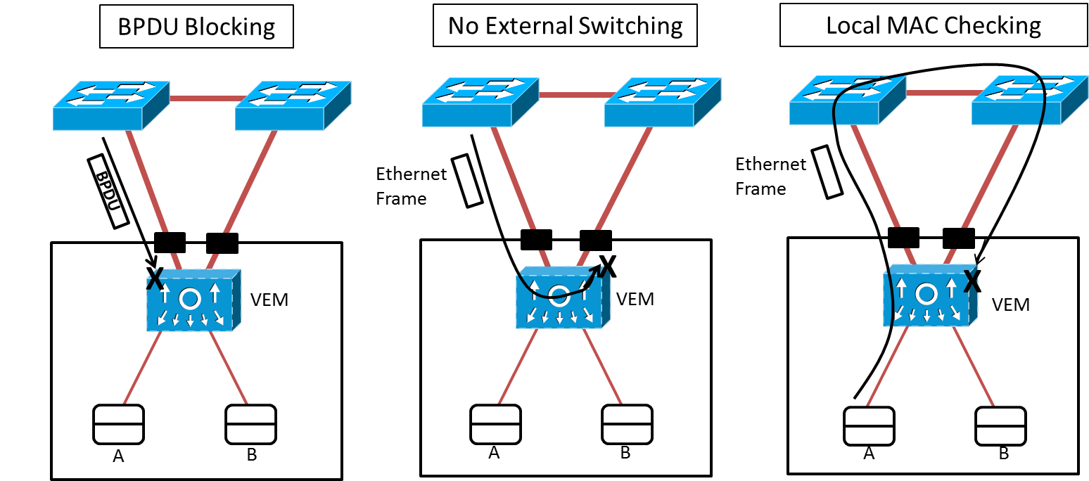
Figure 2: End-Host Mode
In the figure, the VEM:
- Does not accept or send BPDU frames to the physical network
- Does not switch a frame between physical NICs
- Does not accept an incoming frame that has a source address from a virtual machine (luckily registered as a static entry in the MAC address table)
Note: As the most astute readers may observe, End-Host Mode also defines the default forwarding behavior of the UCS Fabric Interconnect, displaying how entangled the development of physical and virtual network have become in the last years.
Difference #4: Control and Data Planes Separation
A great part of the conceptual changes proposed by software-defined networking (SDN) evangelists are not completely new. Actually, one of the many SDN flavors (control and data plane separation) is already part of Nexus 1000V architecture since its first release in 2009.
In this switch, the VSM pair represents the control plane while the VEMs embody the forwarding plane. Such characteristic allows a single Nexus 1000V instance to span multiple data center sites and still maintain the illusion of a single network device. In addition, its privileged central position allows a better orchestration of resources and configuration.
Difference#5: Virtual Extensible VLAN (VXLAN)
Generically speaking, VLANs offer a nice model for the separation of security domains within a physical network. Through the isolation of multi-destination traffic (broadcast and floods), two physical hosts connected to different VLANs depend on other network functions, such as routing, to communicate.
While they are adequate for most data center environments, VLANs present the following limitations against the high scalability of server virtualization environments:
- VLANs permit only the creation of 4094 different domains
- The creation of a VLAN usually depends on configurations on every Layer 2 device in the network, and sometimes, on a Layer 2 extension technology such as Overlay Transport Virtualization (OTV) or Virtual Private LAN Service (VPLS)
- Virtualized servers with hundreds of virtual machines can quickly consume hardware resources (such as MAC address table entries) from the physical network.
To overcome these challenges, Cisco, VMware and other manufacturers have developed a technology called Virtual eXtensible LAN (or simply VXLAN), which was submitted to IETF as a draft in 2010 (http://tools.ietf.org/html/draft-mahalingam-dutt-dcops-vxlan-00). In summary, this technology allows that two different VMs exchange Ethernet frames through the dynamic encapsulation of these frames into UDP datagrams marked with 24-bit VXLAN segment identifiers.
Nexus 1000V currently deploys VXLAN according to the Figure 3.
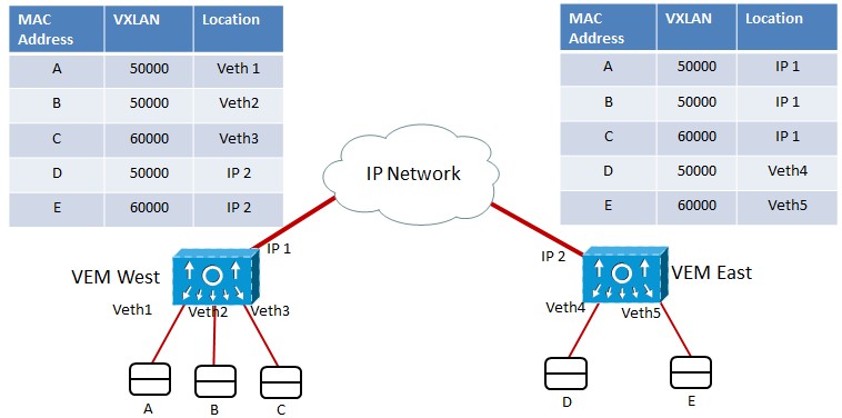
Figure 3: Virtual eXtensible LAN Implementation
In Figure 3, two VEMs share two VXLAN segments (50000 and 60000). For VMs A and B, VEM West performs transparent bridging exactly like it would for a VLAN. Differences arise when hosts from the same VXLAN are connected to different VEMs. In this case, frames are encapsulated into UDP datagrams (VXLAN packets) before they are sent to the remote VEM and VXLAN multidestination traffic is handled via a multicast group.
Note: With NX-OS version 2.2, Nexus 1000V can deploy VXLAN using unicast traffic only. Nonetheless, this model requires that all VEMs sharing a VXLAN segment must be controlled by the same VSM pair.
Yes, I know what you may be thinking. However, even though VXLAN and OTV might share some similarities such as UDP encapsulation and the choice between unicast and multicast, they exhibit important differences that are represented on table 2.
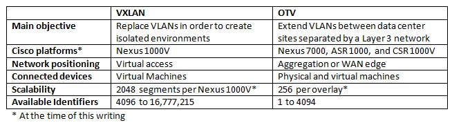
As you can infer, both technologies can be used simultaneously in a single environment. Imagine, for example, a data center that is creating multiple VXLAN segments to work as broadcast domains for VMs from a different tenants (each tenant consumes a VXLAN). In this case, while the VMs would use VXLAN to communicate among themselves, OTV could be used to:
- Transport VXLAN packets between sites
- Extend VLANs that are connected to Layer 3 VXLAN gateways such as ASA 1000V and CSR 1000V or to the new Cisco Layer 2 VXLAN Gateway.
I hope this article has been useful for you.
Best regards, Gustavo.
| Gustavo A. A. Santana - CCIE No. 8806, is a Cisco Technical Solutions Architect working in enterprise and service provider data center projects that require a greater integration among multiple technology areas such as networking, application optimization, storage, and servers. In addition to holding two CCIE certifications (Routing & Switching and Storage Networking), Gustavo is also a VMware Certified Professional (VCP) and an SNIA Certified Storage Networking Expert (SCSN-E). A frequent speaker at Cisco and data center industry events, he blogs on data center virtualization at http://gustavoaasantana.net. |  |
| Data Center Virtualization Fundamentals: Understanding Techniquest and Designs for Highly Efficient Data Centers with Cisco Nexus, UCS, MDS, and Beyond By Gustavo A. A. Santanahttp:// Series: Fundamentals Published: June 21, 2013 Copyright 2013 ISBN-10: 1-58714-324-0 ISBN-13: 978-1-58714-324-3 Published by Cisco Press. |
This article is featured in the July 2013 issue of the Cisco TS Newsletter. Are you subscribed?
Labels:
You must be a registered user to add a comment. If you've already registered, sign in. Otherwise, register and sign in.
Getting Started
Find answers to your questions by entering keywords or phrases in the Search bar above. New here? Use these resources to familiarize yourself with the community:

Customers Also Viewed These Support Documents