- Cisco Community
- Technology and Support
- Data Center and Cloud
- Data Center and Cloud Knowledge Base
- vPC Failover Scenarios and Troubleshooting Checklist
- Subscribe to RSS Feed
- Mark as New
- Mark as Read
- Bookmark
- Subscribe
- Printer Friendly Page
- Report Inappropriate Content
- Subscribe to RSS Feed
- Mark as New
- Mark as Read
- Bookmark
- Subscribe
- Printer Friendly Page
- Report Inappropriate Content
04-30-2013 12:30 AM - edited 03-01-2019 05:58 AM
- Introduction
- vPC Failure Scenario
- vPC Type 1 and Type 2 Consistency Check
- Nexus vPC Troubleshooting Checklist
- Related Information
Introduction
A vPC allows links that are physically connected to two different Cisco Nexus switches to appear as a single port channel to a third switch. The third switch can be a Cisco Nexus 2000 Series Fabric Extender or a switch, server, or any other networking device. The vPC domain includes both vPC peer devices, the vPC peer keepalive link, the vPC peer link, and all the PortChannels in the vPC domain connected to the downstream device.
vPC Failure Scenario
Failure Reaction: vPC peer-link failure (link loss)
In case vPC peer-link fails, check active status of remote vPC peer via vPC pk-link (heartbeat). If both peers are active, then Secondary will disable all vPC ports to prevent loops.
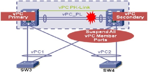
Data will automatically forward down remaining active port channel ports. Failover gated on CFS message failure, or UDLD/Link state detection.
Note: pk-link heartbeat is 1-2/second @ ~64 bytes; failover occurs if 3 hearbeats are missed, on hearbeat received after peer-link fails is considered that the remote peer is alive. Repeat rate and failover times are tunable parameters.
Failure Reaction: vPC peer-link and pk-link fail (Double failure)
This could have many impacts. New incoming L3 messages may fail to make it to their destination (in the case of a vPC member link failure). You will not generate multiple ARPs. PIM will function for L3 Multicast, but messages may be flooded to the non DR switch.
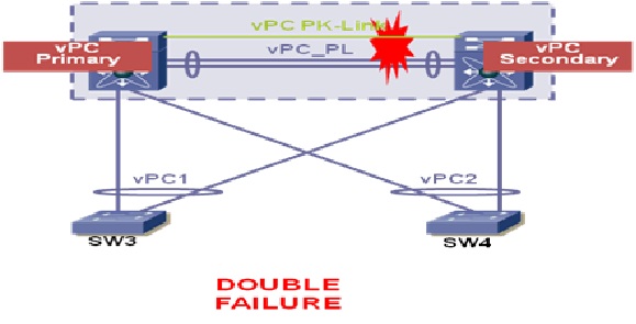
This case is difficult to discover, but using the management port as a pk-link should alert the NOC of a strange environment, due to lack of access to the management interface.
In case vPC peer-link & pk-link fails:
- Check active status of remote vPC peer via vPC pk-link (which fails)
- HSRP/PIM/STP will fail to active on the Secondary vPC peer switch as well as the primary
- Data will continue to forward, but learning will be broken for new flows
- Failover gated on CFS message failure, or UDLD/Link state detection
Failure Reaction: One vPC Peer Switch Failure
If a vPC peer switch the other remaining vPC switch will keep forwarding data. All traffic now moves via this remaining switch and this definitely results in limited bandwidth but does not affect the end point reachability or any services running. In case there was heavy over-subscription of the link, then this may cause some issue, like random traffic drops.
vPC Type 1 and Type 2 Consistency Check
Before a Nexus switch brings up a vPC, the two switches in the same vPC domain exchange configuration information to verify if both switches have compatible configurations for a vPC topology. Depending on the severity of the impact of possible mismatched configurations, some configuration parameters are considered as Type 1 consistency check parameters while others are considered as Type 2.
When a mismatch in Type 1 parameters occur, if a graceful consistency check is enabled (default), the primary switch keeps the vPC up while the secondary switch brings it down. If a graceful consistency check is disabled, both peer switches suspend VLANs on the vPC ports.
When Type 2 parameters exist, a configuration mismatch generates a warning syslog message. The vPC on the switch remains up and running. The global configuration, such as Spanning Tree Protocol (STP), and the interface-level configurations are included in the consistency check.
Nexus vPC Troubleshooting Checklist
- Verify that all vPC interfaces in a vPC domain are configured in the same virtual device context (VDC).
- Verify that you have a separate vPC peer-link and peer-keepalive link infrastructure for each VDC deployed.
- Is the vPC keepalive link mapped to a separate vrf? If not, it will be mapped to the management vrf by default. In this case, do you have a management switch connect to the management ports on both vPC peer devices?
- Verify that both the source and destination IP addresses used for the peer-keepalive messages are reachable from the VRF associated with the vPC peer-keepalive link.
- Verify that the peer-keepalive link is up or the vPC peer-link will not come up.
- Verify that the vPC peer-link is configured as a Layer 2 Port Channel trunk which only allows vPC VLANs.
- Verify that the vPC number that you assigned to the port channel that connects to the downstream device from the vPC peer device is identical on both vPC peer devices.
- If you manually configured the system priority, verify that you assigned the same priority value on both vPC peer devices.
- Check the show vpc consistency-parameters command to verify that both vPC peer devices have identical type-1 parameters.
- Verify that the primary vPC is the primary STP root and the secondary vPC is the secondary STP root.
Related Information
Find answers to your questions by entering keywords or phrases in the Search bar above. New here? Use these resources to familiarize yourself with the community:
